EP1238149B1 - Shoe press unit and method for evacuating oil from a shoe press unit - Google Patents
Shoe press unit and method for evacuating oil from a shoe press unit Download PDFInfo
- Publication number
- EP1238149B1 EP1238149B1 EP00983595A EP00983595A EP1238149B1 EP 1238149 B1 EP1238149 B1 EP 1238149B1 EP 00983595 A EP00983595 A EP 00983595A EP 00983595 A EP00983595 A EP 00983595A EP 1238149 B1 EP1238149 B1 EP 1238149B1
- Authority
- EP
- European Patent Office
- Prior art keywords
- press unit
- shoe
- oil
- shoe press
- evacuation
- Prior art date
- Legal status (The legal status is an assumption and is not a legal conclusion. Google has not performed a legal analysis and makes no representation as to the accuracy of the status listed.)
- Expired - Lifetime
Links
- 238000000034 method Methods 0.000 title claims abstract description 14
- 238000003825 pressing Methods 0.000 claims abstract description 29
- 238000011144 upstream manufacturing Methods 0.000 claims abstract description 19
- 238000007789 sealing Methods 0.000 claims description 15
- 239000002184 metal Substances 0.000 claims description 6
- 239000003921 oil Substances 0.000 claims 11
- 239000010687 lubricating oil Substances 0.000 claims 2
- 239000000463 material Substances 0.000 description 5
- 230000001154 acute effect Effects 0.000 description 3
- 230000001419 dependent effect Effects 0.000 description 2
- 238000010586 diagram Methods 0.000 description 2
- 230000005484 gravity Effects 0.000 description 2
- 239000002861 polymer material Substances 0.000 description 2
- 238000009825 accumulation Methods 0.000 description 1
- 238000010276 construction Methods 0.000 description 1
- 238000006073 displacement reaction Methods 0.000 description 1
- 238000005265 energy consumption Methods 0.000 description 1
- 239000004744 fabric Substances 0.000 description 1
- 239000000835 fiber Substances 0.000 description 1
- 230000020169 heat generation Effects 0.000 description 1
- 238000009434 installation Methods 0.000 description 1
- 238000003466 welding Methods 0.000 description 1
Images


Classifications
-
- D—TEXTILES; PAPER
- D21—PAPER-MAKING; PRODUCTION OF CELLULOSE
- D21F—PAPER-MAKING MACHINES; METHODS OF PRODUCING PAPER THEREON
- D21F3/00—Press section of machines for making continuous webs of paper
- D21F3/02—Wet presses
- D21F3/0209—Wet presses with extended press nip
- D21F3/0218—Shoe presses
Definitions
- the invention relates to a method for oil evacuation from a shoe press unit, which shoe press unit comprises a beam, a shoe element arranged movably on said beam by means of a pressing unit and having a pressing surface, an oil evacuation arrangement with at least one inlet opening, a number of evacuation ducts and an outlet pipe, and also a flexible belt interacting with said shoe element, oil being supplied during operation to lubricate between said pressing surface and said belt, an oil excess with kinetic energy being pressed out at an upstream edge region of said pressing surface, and an oil excess being evacuated from said shoe press unit by said oil evacuation arrangement, at least part of said oil excess being squirted directly into said inlet opening.
- the invention also relates to a shoe press unit.
- a method and a device for a shoe press unit as described above under technical field are previously known from, for example, US 5,935,385.
- oil is supplied during operation in order to lubricate and cool between said pressing surface and said belt.
- the oil is supplied in an excess which is pressed out at an upstream edge region (on the belt entry side) of said pressing surface.
- the oil excess is then evacuated from said shoe press unit by an oil evacuation arrangement.
- the inlet opening to said oil evacuation arrangement is arranged on the beam and at a distance from the shoe element. Therefore, the evacuation arrangement does not move together with the shoe.
- the positioning and arrangement of the inlet opening means that a large part of the kinetic energy from the pressed-out oil is useful for evacuation of excess oil.
- the construction of the oil evacuation arrangement results in efficient evacuation being brought about.
- the invention makes it possible for the temperature in the shoe press unit to be kept at a lower level because a large part of the hot oil is evacuated without having time to give off its heat inside the shoe press unit.
- the efficient evacuation results in a reduction in the energy consumption for operation of the shoe press unit because no or only an insignificant quantity of excess oil accumulates inside the shoe press unit.
- the invention also relates to a shoe press unit according to claim 9.
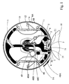
- Fig. 1 shows in cross section the principles of a shoe press unit according to the invention.
- the shoe press unit comprises a support beam 1, in which a recess is arranged for a pressing unit 3, 5 for a shoe element 2.
- the pressing unit 3, 5 consists in a manner known per se of a hydraulic piston which is arranged in a sealing manner inside a hydraulic cylinder 5, so that the shoe element 2 can be moved hydraulically to and fro in a direction which is at right angles in relation to the extent of the shoe element 2 in the cross machine direction.
- a support heel 9 is arranged at one short end of the shoe element 2.
- An endless, flexible belt/jacket 6 is arranged in a manner known per se so as to interact, by means of its one surface 6A, with a pressing surface 21 of the shoe element 2 and, by means of its other surface 6B, with a counter-roll 10.
- the endless belt 6 rotates anti-clockwise, as illustrated in the diagram.
- the heel 9 is therefore arranged at the downstream end of the shoe element 2.
- a distribution chamber 7 Arranged to the left in the diagram of the upstream end of the shoe element is a distribution chamber 7 which in a known manner supplies the pressing surface 21 with oil via ducts 71.
- an oil evacuation arrangement 4 which comprises an inlet opening 41 arranged in a trough-shaped container (see Fig.
- a first evacuation duct 48A a rubber bellows 48C
- an upper connection duct 48B an outlet pipe 49.
- the two ducts 48A, 48B are suitably made from a dimensionally stable material, for example metal, so that they cannot be compressed by outer overpressure.
- Fig. 1 also shows that the shoe press unit is provided with a secondary oil evacuation arrangement 11 which is suitably used as an oil evacuation system when at a standstill.
- the figure also shows that the shoe press unit is provided with belt guides 12 which are arranged on a support plate 13 and the purpose of which is to make possible installation/removal of the belt/jacket 6.
- Fig. 2 shows in greater detail certain parts of a shoe press unit according to the invention.
- the shoe element 2 is of symmetrical design, according to the preferred embodiment shown, in each edge region of said pressing surface 21.
- an edge region Z 1 -Z 2 is marked, which constitutes a region with a convexly curved surface 21 A.
- the extent L of this edge region 2 1 A is considerably shorter than the concave part 21 of the pressing surface.
- a line X at which contact first takes place between the belt 6 and the pressing surface 21 of the shoe element.
- the lower part of the oil evacuation arrangement 4 Arranged on the distribution chamber 7 is the lower part of the oil evacuation arrangement 4.
- the latter comprises a guide plate 42, a container 45, 44, 46, 43A, 43B, an evacuation duct 48 and the inlet opening 41 which is slot-shaped.
- the container consists of a first longitudinal wall element 45, a plane bottom 44, a second longitudinal wall element 46 and two end walls 43A, 43B.
- the upstream longitudinal wall 46 is divided into a lower section 46A and an upper section 46B.
- the lower wall section 46A is arranged at an acute angle in relation to the bottom 44 and a plane P which contains the plane bottom 44. According to the preferred embodiment, the angle ⁇ is approximately 60-70°.
- the upper section 46B is arranged at a smaller acute angle in relation to said plane P.
- the upper section 46B is imparted an inclination which differs only by a few degrees from the tangent of the belt 6 in the region of said upper section 46B.
- the upper section therefore converges slightly towards the inner surface of the belt.
- the end 41B of the upper section forms the second delimiting surface of the inlet opening 41. It is advantageous if this second delimiting surface 41B is positioned close to, or in certain cases even in contact with, the inner surface of the belt 6, so that as small a gap as possible is formed between them.
- the downstream wall element 45 is also arranged at an acute angle in relation to said plane P. According to the preferred embodiment, it forms an angle ⁇ which is essentially the same as the angle ⁇ of the other wall element 46A.
- End walls 43A, 43B are arranged at either short end of the container.
- the first delimiting surface 41A of the inlet opening 41 is formed by the upper edge of the downstream longitudinal wall element 45. All the components forming part of the container are made of thin sheet metal. In the preferred case, the sheet is 2 mm thick.
- Extending at right angles from said first delimiting surface 41 A in the direction of and up to the shoe element 2 is a guide plate 42.
- the guide plate 42 is also made from thin sheet metal and it and the container are suitably made from one and the same piece of sheet metal which is suitably first stamped out and then bent into the desired final shape, after which the end walls 43A, 43B are connected in a sealing manner, suitably by means of welding, to the parts which have been bent up to form the container.
- a circular hole 44A Arranged in the bottom of the container is a circular hole 44A, in which an evacuation pipe 48A is arranged, suitably welded, in a sealing manner.
- the container is fixed by means of screw connections 50 to the distribution chamber 7 which is in turn connected (usually screwed) to one longitudinal side wall 23 of the shoe element.
- the evacuation arrangement 4 is therefore firmly anchored on the shoe element 2, so that these are movable as a unit.
- the evacuation arrangement 4 is positioned with its second delimiting surface 41B of the inlet opening 41 relatively close to the surface of the belt, so that the distance S between them during operation is sufficiently small to prevent any significant quantity of oil escaping between the inlet opening 41 and the belt 6.
- the distance S should preferably not be permitted to exceed 10 mm.
- the inlet opening 41 should moreover be positioned in such a manner that the quantity of excess oil which is pressed out can squirt directly into the inlet opening 41. According to the preferred embodiment, this is brought about by virtue of the fact that the tangent Tx of the convexly curved surface at the contact line X between the belt 6 and the shoe element 2 extends between the first delimiting surface 41A and the second delimiting surface 41B.
- the geometries between said edge region 21 A and the inlet opening should be arranged so that the tangent Tx (which can be considered to represent a kind of median vector for the oil excess which normally squirts out in a divergent manner) of said contact line X deviates by a maximum of 15° from at least one of the imaginary straight lines Y1 and Y2 which extend between said contact line X and the first delimiting surface 41 A and, respectively, the second delimiting surface 41B of the inlet opening 41.
- the inlet opening 41 should be positioned close to the upstream edge region 21A, suitably between 10-150 mm, but more preferably at a maximum of 100 mm, from the edge region 21A.
- the device according to Figs 1 and 2 functions in the following manner.
- the inner surface of the belt is provided with an oil film in order to lubricate between the belt 6 and the pressing surface 21 of the shoe element 2 but also in order to cool the shoe press unit.
- Oil supply usually takes place in a number of different positions, inter alia through the distribution chamber 7 which lubricates in the central zone of said pressing surface 21 (see Fig. 1) and also usually at least somewhere else directly on the inner surface of the belt.
- the shoe press unit is operated in a manner known per se, the shoe element 2 exerting, by means of the pressing unit 3, 5, a pressure against the counter-roll 10 so that a fibre web lying in between is subjected to the desired treatment, for example dewatering.
- the oil excess which accompanies the belt 6 to the upstream end of the shoe element will be pressed out of the converging zone formed between the inner surface 6A of the belt and the upstream edge region 21 A of the shoe element.
- the excess oil O is in this way imparted kinetic energy and will squirt backwards, counter to the direction of movement of the belt, into the inlet opening 41 to be collected inside the container 43A, 43B, 44, 45, 46.
- the oil collected in the container will be pressed out through the first part 48A of the evacuation duct, on through the rubber bellows 48C and then, via the connection pipe 48B, into the outlet pipe 49, to arrive finally in a collecting vessel (not shown).
- the outlet pipe 49 is connected to an underpressure in order to ensure adequate oil evacuation. It is usual to try to operate a closed shoe press unit with an inner overpressure of less than 50 mbar.
- Fig. 3 shows in perspective the abovementioned container 43A, 43B, 44, 45, 46 in the form of a unit with a guide plate 42 and an evacuation pipe 48A. It can also be seen that the guide plate 42 is provided with a number of holes 47 for arranging fixing screws 50.
- the evacuation arrangement in the preferred case is sectioned, in such a manner that a number of containers of limited length are arranged next to one another on the shoe element 2, the inlet opening 41, which preferably extends along the entire width of the container, of each container will always be optimally positioned in relation to the squirting oil irrespective of deflection of the beam 1.
- the length of each container is approximately 1 metre.
- the length of a container should suitably not be less than 500 mm or more than 1500 mm, so that optimum evacuation can be achieved.
- the diameter of the evacuation duct/pipe should not be too small; suitably it is approximately 60 mm.
- the diameter should preferably not be less than 10 mm and should suitably not exceed 50 mm.
- Fig. 4 shows a first alternative embodiment according to the invention, the evacuation duct 48 being provided with two telescopically arranged parts 48A, 48B.
- the first part 48A of the evacuation duct is in this connection provided with a relatively large diameter D1
- the second part 48B of the evacuation duct is provided with a considerably smaller diameter D2.
- the two duct parts are arranged so that, in the rest position, they overlap over a considerable length 1 which is preferably at least the same as the diameter of the first duct part 48A.
- a seal 61 Arranged in the annular gap 60 formed between the overlapping pipe parts is a seal 61 which, according to the preferred embodiment, is fixed to the end of the second duct part 48B. Movement is therefore possible between the seal 61 and the first duct part 48A, a sliding movement taking place in the cylindrical contact region 62 between the seal 61 and the inner surface of the first duct part 48A.
- the evacuation pipe 48A which is fixed to the container is sufficiently long to be capable of entering the outlet pipe 49 through its opening 49A.
- a seal for example one or more O-rings, is arranged directly in the opening 49A on the outlet pipe 49, these seals interacting directly with the outer surface of the evacuation pipe 48A.
- the sealing connection between the first duct part 48A and the adjacent part of the oil evacuation arrangement is flexible in more than one direction so that the connection is flexible in the lateral direction also, because the shoe element can during operation be caused (by lateral forces and/or heat) to make certain lateral movements, which movements the first duct part 48A has to be capable of following without the risk of complications.
- the evacuation arrangement can be made of many other materials than thin sheet metal, for example a polymer material. It is also clear that the inlet opening 41 of the evacuation arrangement can be divided (for example for reasons of strength) so that a number of to a greater or lesser extent elongate openings next to one another is formed. It is also clear that the component parts of the evacuation arrangement do not necessarily have to made of/from one and the same material, but can be made from a number of different components/materials, which can be arranged with/connected to one another in many alternative ways which will be self-evident to the person skilled in the art.
- the evacuation arrangement is arranged on a distribution chamber.
- the evacuation arrangement can of course be arranged directly on the shoe element 2 for example, along its side surface 23 for example.
- the container can consist of a device of very different design from that shown above, for example with a considerably smaller "container space” and/or with a cross-sectional shape which is entirely different (for example oval), according to the space available in the shoe press for which it is intended to be used.
- devices other than a rubber bellows 48C can be provided for making the flexible, sealing connection between two part pipes in the evacuation arrangement, for example a fibre-reinforced flexible and impermeable polymer material other than rubber, or a liquidtight fabric material.
Landscapes
- Paper (AREA)
- Press Drives And Press Lines (AREA)
- Presses And Accessory Devices Thereof (AREA)
- Mounting, Exchange, And Manufacturing Of Dies (AREA)
- Footwear And Its Accessory, Manufacturing Method And Apparatuses (AREA)
Abstract
Description
- Fig. 1
- shows a preferred embodiment of the invention in cross section,
- Fig. 2
- shows a preferred embodiment of the invention partly in cross section, installed in a closed shoe press unit,
- Fig. 3
- shows a perspective view of a preferred component according to the invention, and
- Fig. 4
- shows in cross section an alternative embodiment of an evacuation duct according to the invention.
Claims (20)
- Method for evacuating oil from a shoe press unit, which shoe press unit comprises a beam (1) and a shoe element (2) movably arranged on said beam (1) by means of a pressing unit (3, 5), said shoe element (2) having a pressing surface (21) with an upstream edge region (21 A), said upstream edge region (21 A) comprising a convexly curved surface, the shoe press unit further comprising a rotatable flexible endless belt (6) interacting with said pressing surface (21) of said shoe element (2) and arranged in such a way that the upstream contact line (X) of said belt (6) with said shoe element (2) is located on said convexly curved surface, lubricating oil being supplied during operation between said pressing surface (21) and said belt (6), wherein an oil excess pressed out with kinetic energy at said upstream edge region (21 A) is evacuated from said shoe press unit by means of an oil evacuation arrangement (4) comprising an inlet opening (41) and an evacuation duct (48), characterized in that said inlet opening (41) is formed by a container firmly connected to said shoe element (2) on the upstream side thereof, to which container said evacuation duct (48) is connected, that said inlet opening (41) is arranged so that the tangent (Tx) to said convexly curved surface at said contact line (X) extends into said inlet opening (41), whereby a large part of said oil excess is squirted directly into said inlet opening (41 ), that said evacuation duct (48) is connected to an outlet pipe (49) firmly connected to said beam (1), and that at least a part of said evacuation duct (48) is movably arranged with respect to said outlet pipe (49).
- Method according to claim 1, characterized in that said evacuation duct (48) comprises a first tubular part (48A) which is firmly connected to said container, said first tubular part (48A) being preferably essentially rigid.
- Method according to claim 2, characterized in that said first tubular part (48A) is arranged movable inside a through-hole (1A) in said beam (1) and is of sufficient length to project on the other side of said through-hole (1A).
- Method according to claim 3, characterized in that said first tubular part (48A) is arranged movable with respect to said outlet pipe (49) while being connected thereto in a sealing manner.
- Method according to claim 4, characterized in that the connection between said first tubular part (48A) and said outlet pipe (49) comprises a sealing means in form of a flexible tubular means (48C), such as a rubber bellow.
- Method according to claim 5, characterized in that said flexible tubular means (48C) is connected at one end to said first tubular part (48A) and at the other end to a second tubular part (48B) of said evacuation duct (48) which is firmly connected to said outlet pipe (49).
- Method according to claim 1, characterized in that said shoe press unit is a closed shoe press unit which is operated with an inner overpressure lying between 10 and 500 mbar, preferably below 200 mbar and more preferably below 50 mbar.
- Method according to claim 7, characterized in that said outlet pipe (49) is connected to an underpressure acting from outside the shoe press unit in order to ease the evacuation of said oil excess.
- Shoe press unit comprising:a beam (1),a shoe element (2) movably arranged on said beam (1) by means of a pressing unit (3, 5), said shoe element (2) having a pressing surface (21) with an upstream edge region (21A), said upstream edge region (21A) comprising a convexly curved surface,a rotatable flexible endless belt (6) interacting with said pressing surface (21) of said shoe element (2) and arranged in such a way that the upstream contact line (X) of said belt (6) with said shoe element (2) is located on said convexly curved surface,means (7) for supplying lubricating oil during operation between said pressing surface (21) and said belt (6), andan oil evacuation arrangement (4) for evacuating an oil excess pressed out during operation at said upstream edge region (21A), said oil evacuation arrangement (4) comprising an inlet opening (41) and an evacuation duct (48), characterized in that said oil evacuation arrangement (4) comprises at least one container forming said inlet opening (41), which container is firmly connected to said shoe element (2) on the upstream side thereof, and to which container said evacuation duct (48) is connected, that said inlet opening (41) is arranged so that the tangent (Tx) to said convexly curved surface at said contact line (X) extends into said inlet opening (41), whereby a large part of said oil excess is squirted directly into said inlet opening (41), that said evacuation duct (48) is connected to an outlet pipe (49) firmly connected to said beam (1), and that at least a part of said evacuation duct (48) is movably arranged with respect to said outlet pipe (49).
- Shoe press unit according to claim 9, characterized in that said evacuation duct (48) comprises a movable part (48A) firmly connected to said container in a sealing manner, said container preferably comprising side wall elements (43A, 43B, 45, 46) and a bottom wall element (44).
- Shoe press unit according to claim 10, characterized in that said movable part (48A) interacts with a sealing means (48C, 61) in such a way that said movable part (48A) is connected to said outlet pipe (49) in an essentially sealed manner.
- Shoe press unit according to claim 11, characterized in that said sealing means comprises a flexible tubular device (48C), preferably a rubber bellow, said flexible tubular device (48C) being connected at one end sealingly around said movable part (48A) and at the other end to a second part (48B) of said evacuation duct (48), which second part (48B) is firmly connected to said outlet pipe (49).
- Shoe press unit according to claim 12, characterized in that said second part (48B) consists of a tubular connection piece, preferably a metal pipe, which connection piece is connected to said outlet pipe (49) in a sealing manner.
- Shoe press unit according to claim 11, characterized in that said sealing means is arranged at an inlet opening (49A) of said outlet pipe (49), said sealing means interacting directly with the outer surface of said movable part (48A) at one end thereof, said sealing means preferably comprising at least one O-ring.
- Shoe press unit according to claim 11, characterized in that said movable part (48A) is tubular, that said evacuation duct (48) comprises a second tubular part (48B), said movable tubular part (48A) and said second tubular part (48B) being telescopically arranged with respect to one another, and that said sealing means (61) is arranged in an annular gap formed between the overlapping parts of said movable tubular part (48A) and said second tubular part (48B).
- Shoe press unit according to claim 10, characterized in that said inlet opening (41) is delimited by first and second delimiting surfaces (41A, 41B) extending in a cross-machine direction, said first delimiting surface (41A) being located relatively farther from the belt (6) and said second delimiting surface (41B) being located relatively closer to the belt (6), and that a shielding means (42) is provided in the region between the shoe element (2) and said first delimiting surface (41A), said shielding means (42) extending preferably substantially rectilinearly.
- Shoe press unit according to claim 16, characterized in that the shortest distance (S) between said second delimiting surface (41B) and the inner surface (6A) of said belt (6) is between 0 and 10 mm and is preferably less than 5 mm.
- Shoe press unit according to claim 10, characterized in that the cross-machine direction extent of said container is between 500 and 1500 mm.
- Shoe press unit according to claim 10, characterized in that said movable part (48A) has a diameter of between 30 and 100 mm, preferably of between 50 and 70 mm.
- Shoe press unit according to claim 18, characterized in that said oil evacuation arrangement (4) comprises at least two containers arranged next to each other inside said press shoe unit.
Applications Claiming Priority (3)
| Application Number | Priority Date | Filing Date | Title |
|---|---|---|---|
| SE9904493A SE515926C2 (en) | 1999-12-08 | 1999-12-08 | Method and apparatus for oil evacuation from a shoe press unit |
| SE9904493 | 1999-12-08 | ||
| PCT/SE2000/002284 WO2001042560A1 (en) | 1999-12-08 | 2000-11-21 | Method and device for oil evacuation from a shoe press unit |
Publications (2)
| Publication Number | Publication Date |
|---|---|
| EP1238149A1 EP1238149A1 (en) | 2002-09-11 |
| EP1238149B1 true EP1238149B1 (en) | 2005-04-13 |
Family
ID=20418049
Family Applications (1)
| Application Number | Title | Priority Date | Filing Date |
|---|---|---|---|
| EP00983595A Expired - Lifetime EP1238149B1 (en) | 1999-12-08 | 2000-11-21 | Shoe press unit and method for evacuating oil from a shoe press unit |
Country Status (9)
| Country | Link |
|---|---|
| EP (1) | EP1238149B1 (en) |
| JP (1) | JP4694076B2 (en) |
| CN (1) | CN1170982C (en) |
| AT (1) | ATE293182T1 (en) |
| AU (1) | AU2032801A (en) |
| CA (1) | CA2392496C (en) |
| DE (1) | DE60019453T2 (en) |
| SE (1) | SE515926C2 (en) |
| WO (1) | WO2001042560A1 (en) |
Cited By (1)
| Publication number | Priority date | Publication date | Assignee | Title |
|---|---|---|---|---|
| EP2327834A1 (en) | 2009-11-26 | 2011-06-01 | Metso Paper Inc. | Arrangement and method for removing oil from a shoe press in a fiber web machine |
Families Citing this family (7)
| Publication number | Priority date | Publication date | Assignee | Title |
|---|---|---|---|---|
| DE10154862A1 (en) * | 2001-11-08 | 2003-05-22 | Voith Paper Patent Gmbh | Device for draining liquid |
| JP2005221027A (en) * | 2004-02-06 | 2005-08-18 | Mitsubishi Heavy Ind Ltd | Oil collecting device for roll device |
| US6854301B1 (en) * | 2004-04-13 | 2005-02-15 | Albany International Corp. | Extended nip press for the leather industry |
| DE102004025778A1 (en) * | 2004-05-26 | 2005-12-22 | Voith Paper Patent Gmbh | shoe roll |
| CN102517960B (en) * | 2012-01-10 | 2014-03-19 | 山东昌华造纸机械有限公司 | Boot type squeezing device |
| DE102012205185A1 (en) * | 2012-03-30 | 2013-10-02 | Voith Patent Gmbh | Pressing device for use in machine for producing fibrous web, such as paper, cardboard, tissue or cellulose web, comprises tank provided for receiving hydraulic and lubricating oil, where tank is arranged inside casing of press roll |
| CN109594391A (en) * | 2018-12-25 | 2019-04-09 | 江苏理文造纸有限公司 | A kind of modified shoe press |
Family Cites Families (5)
| Publication number | Priority date | Publication date | Assignee | Title |
|---|---|---|---|---|
| DE3311996A1 (en) * | 1983-04-02 | 1984-10-04 | J.M. Voith Gmbh, 7920 Heidenheim | Process for passing a liquid stream through a belt press unit, and belt press unit in which the process is applicable |
| DE3832324A1 (en) * | 1988-09-23 | 1990-04-05 | Voith Gmbh J M | LONG GAP PRESS ROLLER |
| SE464922B (en) * | 1990-05-08 | 1991-07-01 | Valmet Paper Machinery Inc | PRESS ROLL |
| DE4402754A1 (en) * | 1994-01-31 | 1994-06-16 | Voith Gmbh J M | Pressure element - with collector unit in oil siphon system which is mounted at points least influenced by beam deflections |
| DE19615654A1 (en) * | 1996-04-19 | 1997-10-23 | Voith Sulzer Papiermasch Gmbh | Pressure shoe for flexible pressure cylinder for paper manufacture |
-
1999
- 1999-12-08 SE SE9904493A patent/SE515926C2/en not_active IP Right Cessation
-
2000
- 2000-11-21 WO PCT/SE2000/002284 patent/WO2001042560A1/en not_active Ceased
- 2000-11-21 AT AT00983595T patent/ATE293182T1/en not_active IP Right Cessation
- 2000-11-21 EP EP00983595A patent/EP1238149B1/en not_active Expired - Lifetime
- 2000-11-21 JP JP2001544424A patent/JP4694076B2/en not_active Expired - Fee Related
- 2000-11-21 DE DE60019453T patent/DE60019453T2/en not_active Expired - Lifetime
- 2000-11-21 CA CA002392496A patent/CA2392496C/en not_active Expired - Fee Related
- 2000-11-21 AU AU20328/01A patent/AU2032801A/en not_active Abandoned
- 2000-11-21 CN CNB008162441A patent/CN1170982C/en not_active Expired - Lifetime
Cited By (1)
| Publication number | Priority date | Publication date | Assignee | Title |
|---|---|---|---|---|
| EP2327834A1 (en) | 2009-11-26 | 2011-06-01 | Metso Paper Inc. | Arrangement and method for removing oil from a shoe press in a fiber web machine |
Also Published As
| Publication number | Publication date |
|---|---|
| CN1170982C (en) | 2004-10-13 |
| CA2392496C (en) | 2008-09-23 |
| SE9904493D0 (en) | 1999-12-08 |
| AU2032801A (en) | 2001-06-18 |
| JP4694076B2 (en) | 2011-06-01 |
| JP2003516483A (en) | 2003-05-13 |
| ATE293182T1 (en) | 2005-04-15 |
| SE515926C2 (en) | 2001-10-29 |
| SE9904493L (en) | 2001-06-09 |
| DE60019453D1 (en) | 2005-05-19 |
| CA2392496A1 (en) | 2001-06-14 |
| DE60019453T2 (en) | 2006-02-23 |
| EP1238149A1 (en) | 2002-09-11 |
| CN1399695A (en) | 2003-02-26 |
| WO2001042560A1 (en) | 2001-06-14 |
Similar Documents
| Publication | Publication Date | Title |
|---|---|---|
| CA1322122C (en) | Press with extended nip | |
| US20090321033A1 (en) | Methods of forming an extended nip in a web-treatment apparatus and controlling load in the nip, employing an elastic support body as one of the nip-forming elements | |
| EP2013412B1 (en) | Support body for an apparatus having an extended nip for the treatment of a fibre web | |
| US4576682A (en) | Long-nip press for a paper making machine | |
| CA1318806C (en) | Press with extended nip | |
| FI99035C (en) | Seal construction for the suction roller in a paper machine | |
| CA2392496C (en) | Method and device for oil evacuation from a shoe press unit | |
| EP1238147B1 (en) | Method for evacuatiing oil from a shoe press unit and shoe press unit | |
| US6402890B1 (en) | Method and device for oil evacuation from a shoe press unit | |
| CA2271199C (en) | Method for loading the sealing of a suction roll and a sealing thereof | |
| EP0147352A1 (en) | Extended nip press | |
| EP3913133B1 (en) | Sleeve roll for a wire section of a fiber web machine | |
| CN102517960A (en) | Boot type squeezing device | |
| US6387216B1 (en) | Long shoeless nip press | |
| MXPA06003016A (en) | Support body, holding device therefor, apparatus with such a body for treatment of a web, methods of forming an extended nip in the apparatus and controlling load in the nip |
Legal Events
| Date | Code | Title | Description |
|---|---|---|---|
| PUAI | Public reference made under article 153(3) epc to a published international application that has entered the european phase |
Free format text: ORIGINAL CODE: 0009012 |
|
| 17P | Request for examination filed |
Effective date: 20020325 |
|
| AK | Designated contracting states |
Kind code of ref document: A1 Designated state(s): AT BE CH CY DE DK ES FI FR GB GR IE IT LI LU MC NL PT SE TR |
|
| AX | Request for extension of the european patent |
Free format text: AL;LT;LV;MK;RO;SI |
|
| 17Q | First examination report despatched |
Effective date: 20040408 |
|
| RAP1 | Party data changed (applicant data changed or rights of an application transferred) |
Owner name: METSO PAPER, INC. |
|
| RAP1 | Party data changed (applicant data changed or rights of an application transferred) |
Owner name: METSO PAPER, INC. |
|
| GRAP | Despatch of communication of intention to grant a patent |
Free format text: ORIGINAL CODE: EPIDOSNIGR1 |
|
| RTI1 | Title (correction) |
Free format text: SHOE PRESS UNIT AND METHOD FOR EVACUATING OIL FROM A SHOE PRESS UNIT |
|
| GRAS | Grant fee paid |
Free format text: ORIGINAL CODE: EPIDOSNIGR3 |
|
| GRAA | (expected) grant |
Free format text: ORIGINAL CODE: 0009210 |
|
| AK | Designated contracting states |
Kind code of ref document: B1 Designated state(s): AT BE CH CY DE DK ES FI FR GB GR IE IT LI LU MC NL PT SE TR |
|
| PG25 | Lapsed in a contracting state [announced via postgrant information from national office to epo] |
Ref country code: AT Free format text: LAPSE BECAUSE OF FAILURE TO SUBMIT A TRANSLATION OF THE DESCRIPTION OR TO PAY THE FEE WITHIN THE PRESCRIBED TIME-LIMIT Effective date: 20050413 Ref country code: FI Free format text: LAPSE BECAUSE OF FAILURE TO SUBMIT A TRANSLATION OF THE DESCRIPTION OR TO PAY THE FEE WITHIN THE PRESCRIBED TIME-LIMIT Effective date: 20050413 Ref country code: LI Free format text: LAPSE BECAUSE OF FAILURE TO SUBMIT A TRANSLATION OF THE DESCRIPTION OR TO PAY THE FEE WITHIN THE PRESCRIBED TIME-LIMIT Effective date: 20050413 Ref country code: CH Free format text: LAPSE BECAUSE OF FAILURE TO SUBMIT A TRANSLATION OF THE DESCRIPTION OR TO PAY THE FEE WITHIN THE PRESCRIBED TIME-LIMIT Effective date: 20050413 Ref country code: BE Free format text: LAPSE BECAUSE OF FAILURE TO SUBMIT A TRANSLATION OF THE DESCRIPTION OR TO PAY THE FEE WITHIN THE PRESCRIBED TIME-LIMIT Effective date: 20050413 Ref country code: NL Free format text: LAPSE BECAUSE OF FAILURE TO SUBMIT A TRANSLATION OF THE DESCRIPTION OR TO PAY THE FEE WITHIN THE PRESCRIBED TIME-LIMIT Effective date: 20050413 Ref country code: TR Free format text: LAPSE BECAUSE OF FAILURE TO SUBMIT A TRANSLATION OF THE DESCRIPTION OR TO PAY THE FEE WITHIN THE PRESCRIBED TIME-LIMIT Effective date: 20050413 Ref country code: IT Free format text: LAPSE BECAUSE OF FAILURE TO SUBMIT A TRANSLATION OF THE DESCRIPTION OR TO PAY THE FEE WITHIN THE PRESCRIBED TIME-LIMIT;WARNING: LAPSES OF ITALIAN PATENTS WITH EFFECTIVE DATE BEFORE 2007 MAY HAVE OCCURRED AT ANY TIME BEFORE 2007. THE CORRECT EFFECTIVE DATE MAY BE DIFFERENT FROM THE ONE RECORDED. Effective date: 20050413 |
|
| REG | Reference to a national code |
Ref country code: GB Ref legal event code: FG4D |
|
| REG | Reference to a national code |
Ref country code: CH Ref legal event code: EP |
|
| REG | Reference to a national code |
Ref country code: IE Ref legal event code: FG4D |
|
| REF | Corresponds to: |
Ref document number: 60019453 Country of ref document: DE Date of ref document: 20050519 Kind code of ref document: P |
|
| PG25 | Lapsed in a contracting state [announced via postgrant information from national office to epo] |
Ref country code: SE Free format text: LAPSE BECAUSE OF FAILURE TO SUBMIT A TRANSLATION OF THE DESCRIPTION OR TO PAY THE FEE WITHIN THE PRESCRIBED TIME-LIMIT Effective date: 20050713 Ref country code: GR Free format text: LAPSE BECAUSE OF FAILURE TO SUBMIT A TRANSLATION OF THE DESCRIPTION OR TO PAY THE FEE WITHIN THE PRESCRIBED TIME-LIMIT Effective date: 20050713 Ref country code: DK Free format text: LAPSE BECAUSE OF FAILURE TO SUBMIT A TRANSLATION OF THE DESCRIPTION OR TO PAY THE FEE WITHIN THE PRESCRIBED TIME-LIMIT Effective date: 20050713 |
|
| PG25 | Lapsed in a contracting state [announced via postgrant information from national office to epo] |
Ref country code: ES Free format text: LAPSE BECAUSE OF FAILURE TO SUBMIT A TRANSLATION OF THE DESCRIPTION OR TO PAY THE FEE WITHIN THE PRESCRIBED TIME-LIMIT Effective date: 20050724 |
|
| PG25 | Lapsed in a contracting state [announced via postgrant information from national office to epo] |
Ref country code: PT Free format text: LAPSE BECAUSE OF FAILURE TO SUBMIT A TRANSLATION OF THE DESCRIPTION OR TO PAY THE FEE WITHIN THE PRESCRIBED TIME-LIMIT Effective date: 20050913 |
|
| NLV1 | Nl: lapsed or annulled due to failure to fulfill the requirements of art. 29p and 29m of the patents act | ||
| REG | Reference to a national code |
Ref country code: CH Ref legal event code: PL |
|
| PG25 | Lapsed in a contracting state [announced via postgrant information from national office to epo] |
Ref country code: GB Free format text: LAPSE BECAUSE OF NON-PAYMENT OF DUE FEES Effective date: 20051121 Ref country code: CY Free format text: LAPSE BECAUSE OF FAILURE TO SUBMIT A TRANSLATION OF THE DESCRIPTION OR TO PAY THE FEE WITHIN THE PRESCRIBED TIME-LIMIT Effective date: 20051121 Ref country code: IE Free format text: LAPSE BECAUSE OF NON-PAYMENT OF DUE FEES Effective date: 20051121 |
|
| PG25 | Lapsed in a contracting state [announced via postgrant information from national office to epo] |
Ref country code: MC Free format text: LAPSE BECAUSE OF NON-PAYMENT OF DUE FEES Effective date: 20051130 Ref country code: LU Free format text: LAPSE BECAUSE OF NON-PAYMENT OF DUE FEES Effective date: 20051130 |
|
| PLBE | No opposition filed within time limit |
Free format text: ORIGINAL CODE: 0009261 |
|
| STAA | Information on the status of an ep patent application or granted ep patent |
Free format text: STATUS: NO OPPOSITION FILED WITHIN TIME LIMIT |
|
| 26N | No opposition filed |
Effective date: 20060116 |
|
| EN | Fr: translation not filed | ||
| GBPC | Gb: european patent ceased through non-payment of renewal fee |
Effective date: 20051121 |
|
| REG | Reference to a national code |
Ref country code: IE Ref legal event code: MM4A |
|
| PG25 | Lapsed in a contracting state [announced via postgrant information from national office to epo] |
Ref country code: FR Free format text: LAPSE BECAUSE OF NON-PAYMENT OF DUE FEES Effective date: 20051130 |
|
| PG25 | Lapsed in a contracting state [announced via postgrant information from national office to epo] |
Ref country code: FR Free format text: LAPSE BECAUSE OF NON-PAYMENT OF DUE FEES Effective date: 20050413 |
|
| PGFP | Annual fee paid to national office [announced via postgrant information from national office to epo] |
Ref country code: DE Payment date: 20191121 Year of fee payment: 20 |
|
| REG | Reference to a national code |
Ref country code: DE Ref legal event code: R071 Ref document number: 60019453 Country of ref document: DE |