EP1237707B1 - Procede et dispositif de fabrication d'emballages sans chauffage du film - Google Patents
Procede et dispositif de fabrication d'emballages sans chauffage du film Download PDFInfo
- Publication number
- EP1237707B1 EP1237707B1 EP00979314A EP00979314A EP1237707B1 EP 1237707 B1 EP1237707 B1 EP 1237707B1 EP 00979314 A EP00979314 A EP 00979314A EP 00979314 A EP00979314 A EP 00979314A EP 1237707 B1 EP1237707 B1 EP 1237707B1
- Authority
- EP
- European Patent Office
- Prior art keywords
- film
- hold
- die
- holding plate
- punch
- Prior art date
- Legal status (The legal status is an assumption and is not a legal conclusion. Google has not performed a legal analysis and makes no representation as to the accuracy of the status listed.)
- Expired - Lifetime
Links
- 238000000034 method Methods 0.000 title claims abstract description 52
- 238000010438 heat treatment Methods 0.000 title claims description 8
- 238000012856 packing Methods 0.000 title 1
- 229910052751 metal Inorganic materials 0.000 claims abstract description 27
- 239000002184 metal Substances 0.000 claims abstract description 27
- 239000004033 plastic Substances 0.000 claims abstract description 18
- 229920003023 plastic Polymers 0.000 claims abstract description 18
- 239000011888 foil Substances 0.000 claims description 24
- 238000000465 moulding Methods 0.000 claims description 14
- 238000004806 packaging method and process Methods 0.000 claims description 13
- 239000002131 composite material Substances 0.000 claims description 4
- 238000007493 shaping process Methods 0.000 claims description 3
- 239000011248 coating agent Substances 0.000 claims description 2
- 238000000576 coating method Methods 0.000 claims description 2
- 238000001953 recrystallisation Methods 0.000 claims description 2
- 230000035515 penetration Effects 0.000 claims 2
- 230000009477 glass transition Effects 0.000 claims 1
- 230000000149 penetrating effect Effects 0.000 claims 1
- 230000000284 resting effect Effects 0.000 claims 1
- 239000002905 metal composite material Substances 0.000 abstract description 5
- 239000010408 film Substances 0.000 description 59
- 239000007789 gas Substances 0.000 description 34
- 238000004519 manufacturing process Methods 0.000 description 11
- 239000002985 plastic film Substances 0.000 description 6
- 229920006255 plastic film Polymers 0.000 description 6
- 239000003570 air Substances 0.000 description 5
- IJGRMHOSHXDMSA-UHFFFAOYSA-N Atomic nitrogen Chemical compound N#N IJGRMHOSHXDMSA-UHFFFAOYSA-N 0.000 description 4
- -1 Polyethylene Polymers 0.000 description 4
- 229910052782 aluminium Inorganic materials 0.000 description 3
- XAGFODPZIPBFFR-UHFFFAOYSA-N aluminium Chemical compound [Al] XAGFODPZIPBFFR-UHFFFAOYSA-N 0.000 description 3
- 230000006835 compression Effects 0.000 description 3
- 238000007906 compression Methods 0.000 description 3
- 150000002739 metals Chemical class 0.000 description 3
- XKRFYHLGVUSROY-UHFFFAOYSA-N Argon Chemical compound [Ar] XKRFYHLGVUSROY-UHFFFAOYSA-N 0.000 description 2
- 239000004695 Polyether sulfone Substances 0.000 description 2
- 229910000831 Steel Inorganic materials 0.000 description 2
- XECAHXYUAAWDEL-UHFFFAOYSA-N acrylonitrile butadiene styrene Chemical compound C=CC=C.C=CC#N.C=CC1=CC=CC=C1 XECAHXYUAAWDEL-UHFFFAOYSA-N 0.000 description 2
- 229920000122 acrylonitrile butadiene styrene Polymers 0.000 description 2
- 239000004676 acrylonitrile butadiene styrene Substances 0.000 description 2
- 238000005516 engineering process Methods 0.000 description 2
- 229910052757 nitrogen Inorganic materials 0.000 description 2
- 229920006393 polyether sulfone Polymers 0.000 description 2
- 229920000139 polyethylene terephthalate Polymers 0.000 description 2
- 239000005020 polyethylene terephthalate Substances 0.000 description 2
- 239000004800 polyvinyl chloride Substances 0.000 description 2
- 229920000915 polyvinyl chloride Polymers 0.000 description 2
- 239000010959 steel Substances 0.000 description 2
- 230000003746 surface roughness Effects 0.000 description 2
- 238000003466 welding Methods 0.000 description 2
- RYGMFSIKBFXOCR-UHFFFAOYSA-N Copper Chemical compound [Cu] RYGMFSIKBFXOCR-UHFFFAOYSA-N 0.000 description 1
- 239000004698 Polyethylene Substances 0.000 description 1
- 239000004743 Polypropylene Substances 0.000 description 1
- 239000004793 Polystyrene Substances 0.000 description 1
- BQCADISMDOOEFD-UHFFFAOYSA-N Silver Chemical compound [Ag] BQCADISMDOOEFD-UHFFFAOYSA-N 0.000 description 1
- 239000004809 Teflon Substances 0.000 description 1
- 229920006362 Teflon® Polymers 0.000 description 1
- ATJFFYVFTNAWJD-UHFFFAOYSA-N Tin Chemical compound [Sn] ATJFFYVFTNAWJD-UHFFFAOYSA-N 0.000 description 1
- 229920001893 acrylonitrile styrene Polymers 0.000 description 1
- 238000004026 adhesive bonding Methods 0.000 description 1
- 229910052786 argon Inorganic materials 0.000 description 1
- 229920002301 cellulose acetate Polymers 0.000 description 1
- 239000002826 coolant Substances 0.000 description 1
- 229920001577 copolymer Polymers 0.000 description 1
- 229910052802 copper Inorganic materials 0.000 description 1
- 239000010949 copper Substances 0.000 description 1
- 239000013039 cover film Substances 0.000 description 1
- 238000009826 distribution Methods 0.000 description 1
- 239000011521 glass Substances 0.000 description 1
- PCHJSUWPFVWCPO-UHFFFAOYSA-N gold Chemical compound [Au] PCHJSUWPFVWCPO-UHFFFAOYSA-N 0.000 description 1
- 229910052737 gold Inorganic materials 0.000 description 1
- 239000010931 gold Substances 0.000 description 1
- 239000001307 helium Substances 0.000 description 1
- 229910052734 helium Inorganic materials 0.000 description 1
- SWQJXJOGLNCZEY-UHFFFAOYSA-N helium atom Chemical compound [He] SWQJXJOGLNCZEY-UHFFFAOYSA-N 0.000 description 1
- 230000006698 induction Effects 0.000 description 1
- 239000004922 lacquer Substances 0.000 description 1
- 239000000463 material Substances 0.000 description 1
- 239000000203 mixture Substances 0.000 description 1
- 229920002239 polyacrylonitrile Polymers 0.000 description 1
- 239000004417 polycarbonate Substances 0.000 description 1
- 229920000515 polycarbonate Polymers 0.000 description 1
- 229920000573 polyethylene Polymers 0.000 description 1
- 229920001155 polypropylene Polymers 0.000 description 1
- 229920002223 polystyrene Polymers 0.000 description 1
- 230000002040 relaxant effect Effects 0.000 description 1
- 238000005096 rolling process Methods 0.000 description 1
- 238000007789 sealing Methods 0.000 description 1
- 229910052709 silver Inorganic materials 0.000 description 1
- 239000004332 silver Substances 0.000 description 1
- 239000000725 suspension Substances 0.000 description 1
- 238000005496 tempering Methods 0.000 description 1
- 229920001169 thermoplastic Polymers 0.000 description 1
- 239000004416 thermosoftening plastic Substances 0.000 description 1
- 239000011135 tin Substances 0.000 description 1
- 229910052718 tin Inorganic materials 0.000 description 1
- 230000009466 transformation Effects 0.000 description 1
- 238000009423 ventilation Methods 0.000 description 1
Images


Classifications
-
- B—PERFORMING OPERATIONS; TRANSPORTING
- B29—WORKING OF PLASTICS; WORKING OF SUBSTANCES IN A PLASTIC STATE IN GENERAL
- B29C—SHAPING OR JOINING OF PLASTICS; SHAPING OF MATERIAL IN A PLASTIC STATE, NOT OTHERWISE PROVIDED FOR; AFTER-TREATMENT OF THE SHAPED PRODUCTS, e.g. REPAIRING
- B29C51/00—Shaping by thermoforming, i.e. shaping sheets or sheet like preforms after heating, e.g. shaping sheets in matched moulds or by deep-drawing; Apparatus therefor
- B29C51/04—Combined thermoforming and prestretching, e.g. biaxial stretching
-
- B—PERFORMING OPERATIONS; TRANSPORTING
- B29—WORKING OF PLASTICS; WORKING OF SUBSTANCES IN A PLASTIC STATE IN GENERAL
- B29C—SHAPING OR JOINING OF PLASTICS; SHAPING OF MATERIAL IN A PLASTIC STATE, NOT OTHERWISE PROVIDED FOR; AFTER-TREATMENT OF THE SHAPED PRODUCTS, e.g. REPAIRING
- B29C51/00—Shaping by thermoforming, i.e. shaping sheets or sheet like preforms after heating, e.g. shaping sheets in matched moulds or by deep-drawing; Apparatus therefor
- B29C51/14—Shaping by thermoforming, i.e. shaping sheets or sheet like preforms after heating, e.g. shaping sheets in matched moulds or by deep-drawing; Apparatus therefor using multilayered preforms or sheets
-
- B—PERFORMING OPERATIONS; TRANSPORTING
- B29—WORKING OF PLASTICS; WORKING OF SUBSTANCES IN A PLASTIC STATE IN GENERAL
- B29C—SHAPING OR JOINING OF PLASTICS; SHAPING OF MATERIAL IN A PLASTIC STATE, NOT OTHERWISE PROVIDED FOR; AFTER-TREATMENT OF THE SHAPED PRODUCTS, e.g. REPAIRING
- B29C51/00—Shaping by thermoforming, i.e. shaping sheets or sheet like preforms after heating, e.g. shaping sheets in matched moulds or by deep-drawing; Apparatus therefor
- B29C51/26—Component parts, details or accessories; Auxiliary operations
- B29C51/30—Moulds
- B29C51/38—Opening, closing or clamping means
-
- B—PERFORMING OPERATIONS; TRANSPORTING
- B29—WORKING OF PLASTICS; WORKING OF SUBSTANCES IN A PLASTIC STATE IN GENERAL
- B29C—SHAPING OR JOINING OF PLASTICS; SHAPING OF MATERIAL IN A PLASTIC STATE, NOT OTHERWISE PROVIDED FOR; AFTER-TREATMENT OF THE SHAPED PRODUCTS, e.g. REPAIRING
- B29C67/00—Shaping techniques not covered by groups B29C39/00 - B29C65/00, B29C70/00 or B29C73/00
- B29C67/0029—Cold deforming of thermoplastics material
-
- B—PERFORMING OPERATIONS; TRANSPORTING
- B29—WORKING OF PLASTICS; WORKING OF SUBSTANCES IN A PLASTIC STATE IN GENERAL
- B29C—SHAPING OR JOINING OF PLASTICS; SHAPING OF MATERIAL IN A PLASTIC STATE, NOT OTHERWISE PROVIDED FOR; AFTER-TREATMENT OF THE SHAPED PRODUCTS, e.g. REPAIRING
- B29C43/00—Compression moulding, i.e. applying external pressure to flow the moulding material; Apparatus therefor
- B29C43/02—Compression moulding, i.e. applying external pressure to flow the moulding material; Apparatus therefor of articles of definite length, i.e. discrete articles
- B29C43/14—Compression moulding, i.e. applying external pressure to flow the moulding material; Apparatus therefor of articles of definite length, i.e. discrete articles in several steps
- B29C2043/141—Compression moulding, i.e. applying external pressure to flow the moulding material; Apparatus therefor of articles of definite length, i.e. discrete articles in several steps for making single layer articles
- B29C2043/143—Compression moulding, i.e. applying external pressure to flow the moulding material; Apparatus therefor of articles of definite length, i.e. discrete articles in several steps for making single layer articles stepwise in a vertical direction, i.e. each time modifying the thickness
-
- B—PERFORMING OPERATIONS; TRANSPORTING
- B29—WORKING OF PLASTICS; WORKING OF SUBSTANCES IN A PLASTIC STATE IN GENERAL
- B29C—SHAPING OR JOINING OF PLASTICS; SHAPING OF MATERIAL IN A PLASTIC STATE, NOT OTHERWISE PROVIDED FOR; AFTER-TREATMENT OF THE SHAPED PRODUCTS, e.g. REPAIRING
- B29C43/00—Compression moulding, i.e. applying external pressure to flow the moulding material; Apparatus therefor
- B29C43/32—Component parts, details or accessories; Auxiliary operations
- B29C43/36—Moulds for making articles of definite length, i.e. discrete articles
- B29C43/361—Moulds for making articles of definite length, i.e. discrete articles with pressing members independently movable of the parts for opening or closing the mould, e.g. movable pistons
- B29C2043/3615—Forming elements, e.g. mandrels or rams or stampers or pistons or plungers or punching devices
-
- B—PERFORMING OPERATIONS; TRANSPORTING
- B29—WORKING OF PLASTICS; WORKING OF SUBSTANCES IN A PLASTIC STATE IN GENERAL
- B29C—SHAPING OR JOINING OF PLASTICS; SHAPING OF MATERIAL IN A PLASTIC STATE, NOT OTHERWISE PROVIDED FOR; AFTER-TREATMENT OF THE SHAPED PRODUCTS, e.g. REPAIRING
- B29C2791/00—Shaping characteristics in general
- B29C2791/004—Shaping under special conditions
- B29C2791/007—Using fluid under pressure
-
- B—PERFORMING OPERATIONS; TRANSPORTING
- B29—WORKING OF PLASTICS; WORKING OF SUBSTANCES IN A PLASTIC STATE IN GENERAL
- B29C—SHAPING OR JOINING OF PLASTICS; SHAPING OF MATERIAL IN A PLASTIC STATE, NOT OTHERWISE PROVIDED FOR; AFTER-TREATMENT OF THE SHAPED PRODUCTS, e.g. REPAIRING
- B29C51/00—Shaping by thermoforming, i.e. shaping sheets or sheet like preforms after heating, e.g. shaping sheets in matched moulds or by deep-drawing; Apparatus therefor
- B29C51/08—Deep drawing or matched-mould forming, i.e. using mechanical means only
-
- B—PERFORMING OPERATIONS; TRANSPORTING
- B29—WORKING OF PLASTICS; WORKING OF SUBSTANCES IN A PLASTIC STATE IN GENERAL
- B29C—SHAPING OR JOINING OF PLASTICS; SHAPING OF MATERIAL IN A PLASTIC STATE, NOT OTHERWISE PROVIDED FOR; AFTER-TREATMENT OF THE SHAPED PRODUCTS, e.g. REPAIRING
- B29C51/00—Shaping by thermoforming, i.e. shaping sheets or sheet like preforms after heating, e.g. shaping sheets in matched moulds or by deep-drawing; Apparatus therefor
- B29C51/26—Component parts, details or accessories; Auxiliary operations
- B29C51/261—Handling means, e.g. transfer means, feeding means
- B29C51/262—Clamping means for the sheets, e.g. clamping frames
-
- B—PERFORMING OPERATIONS; TRANSPORTING
- B29—WORKING OF PLASTICS; WORKING OF SUBSTANCES IN A PLASTIC STATE IN GENERAL
- B29K—INDEXING SCHEME ASSOCIATED WITH SUBCLASSES B29B, B29C OR B29D, RELATING TO MOULDING MATERIALS OR TO MATERIALS FOR MOULDS, REINFORCEMENTS, FILLERS OR PREFORMED PARTS, e.g. INSERTS
- B29K2705/00—Use of metals, their alloys or their compounds, for preformed parts, e.g. for inserts
-
- B—PERFORMING OPERATIONS; TRANSPORTING
- B29—WORKING OF PLASTICS; WORKING OF SUBSTANCES IN A PLASTIC STATE IN GENERAL
- B29L—INDEXING SCHEME ASSOCIATED WITH SUBCLASS B29C, RELATING TO PARTICULAR ARTICLES
- B29L2031/00—Other particular articles
- B29L2031/712—Containers; Packaging elements or accessories, Packages
Definitions
- the present invention relates to a method for Manufacture of packaging from plastic-metal composite films, from pure metal or plastic foils Stretching or deep drawing using a stamp combined with Gas pressure or by gas pressure alone as well as a device to carry out this procedure. In particular concerns such a process for the production of blister packs.
- foil packaging is in many ways Terms of importance. Show packaging from foils light weight and are not fragile. Plastic packaging in the form of so-called blisters are particularly easy to manufacture because they only from a plastic film, molded into the recesses (these are referred to in the art as "courtyards", the packaging, consisting of one or more courtyards is called a "blister") and one stuck on it or welded cover film. The one to be packed Good is done before welding the two parts into the courtyards brought in. Instead of pure plastic film, too multilayer films are used, especially multilayer films Foils that have a metallic layer for the purpose Shield from light or moisture. The metal layer can also be just a metallic coating.
- the technology the type of packaging described is known per se.
- From US-A-3 600 753 is a method for forming a plastic film for the production of packaging known in which the film has a mold cavities The die is positioned using parts of the film Stamps are pressed into the ponn cavities, causing courtyards are created in the foil, and the courtyards of be pressurized on its concave side.
- the film is a previously heated one Plastic film, whereby the deformability due to the heating becomes larger, so that the blister area remains the same deeper courtyards can be made. Furthermore take the required forming forces with increasing film temperature from.
- Forming heated plastic-metal composite foils or heated pure metal foils using Compressed gas is not practiced because the foil heats up causes no greater deformability (the achievable Degree of deformation of the film is due to the metallic layer limited, which is in the range of the temperatures mentioned does not behave significantly differently than at room temperature).
- US-A-3 600 753 also discloses an apparatus which includes: a tool with a tool plate and a die having a plurality of mold cavities; a stamp holding plate with several stamps, that the die and the die holder plate can be moved against each other are and the stamp in the mold cavities Immerse; Means for supplying compressed gas, that with punches immersed in the mold cavities, the Mold cavities are pressurized with gas; Means of Locking of the die and stamp holding plate in a certain relative position to each other; as well as one of Plate through which coolant flows between stamp holding plate and die.
- the task is to find a method this is particularly true in the case of plastic-metal composite films as well as in the case of pure metal foils from yards with a large ratio of yard depth to blister area allowed.
- the process should also apply to plastic films can be used.
- the new Process the forming properties of the metallic layer let it be used specifically, so that courtyards with a large ratio Yard depth to blister area can be made.
- step b) of the method according to the invention the film in the side walls of the emerging Courtyards are more stressed than the film in the floor walls the emerging courtyards.
- step c) of the inventive Process is the film in the floor walls more stressed than the film in the side walls the courtyards.
- the new process results in especially when molding with compressed gas, another Stress distribution in the film than in the stretch or Deep drawing using a stamp. This manifests itself particularly for yard geometries with a flat yard floor in a larger one Stability. Prerequisite for reaching this larger one Stability, however, is that shaping Temperatures below the glass temperature of the plastic layers or in the case of pure metal foils below the Recrystallization temperature takes place.
- the courtyards initially mechanically, for example, by means of a die preformed and then finished with gas pressure molded or they become direct without mechanical preforming molded by gas pressure.
- the die points a mold cavity that apart from the elastic Reshaping the film largely to the geometry of the courtyard corresponds to which is to be shaped.
- preforming the film is pressed into the mold cavity in such a way that they only on the form stamp and on the die rounding of the mold cavity.
- gas pressure the film then lies against the mold cavity and thus takes its form.
- This type of transformation (both Preforming like shaping) is used in technology as stretch drawing, Deep drawing or a mixture of the two processes designated.
- foil which comprises a metal layer
- pure metal foils or Plastic / metal composite films consisting of two or more layers are made and of which at least one layer one Is metal layer. In the case of at least three layers, this is Metal layer usually present as one of the inner layers, so that there is a “sandwich” structure.
- the foil is a pure metal foil any sufficiently ductile metal can be used.
- metals are aluminum, copper, Silver, gold and tin.
- the metal for the metal layer of a composite film can be any metal that can be used as a foil (i.e. by gluing or welding) or as a vapor-deposited layer can be applied to a plastic layer.
- a foil i.e. by gluing or welding
- a vapor-deposited layer can be applied to a plastic layer.
- preferred Examples of such metals are those mentioned above Metals.
- plastics for the plastic film or the Plastic layer (s) of a composite film containing a metal layer all plastics are suitable, which are usually used for blister films be used.
- plastics are thermoplastics like polystyrene, Polyethylene, polypropylene, polyvinyl chloride, polyacrylonitrile, Polycarbonate and cellulose acetate and copolymers such as ABS (acrylonitrile butadiene styrene), ASA (acrylonitrile styrene acrylic ester), PET (polyethylene terephthalate) and PES (Polyethersulfone).
- Preferred foils are metal foils or foils, which comprise at least one metal layer, in the latter Case a three-layer plastic / aluminum / plastic composite film is particularly preferred.
- the films which can be used according to the invention are from State of the art of blister production is known. You can used analogously in the process according to the invention become.
- the film deforms "without heating” is meant to mean that no funds are used, whose only or primary function is generation is warm, for example infrared lamps for irradiation the film or the induction heating for heating of tools.
- Heat that impacts the film implicitly e.g. Heat generated by the adiabatic, previous compression of the compressed gas is present in the compressed gas and so with the film comes into contact is not considered heating in the Meaning of the above definition.
- the heat for example, is also sensible when it is pressed in from step b) and / or when applied with Pressurized gas from step c) e.g. at the bends or bends the film is created by rolling it.
- This is implicit Heat supply should therefore not be outside the scope of the application be excluded.
- a such implicit heat on the film for success of the method according to the invention is not essential is.
- the implicit supply of Heat avoided as much as possible, making it a real one Cold forming is concerned.
- step b) applies the maximum distance in the feed direction of the Stamp can occur between the puncture point of the corresponding feed direction line through the surface the die 22, on which the film 1 comes to rest, on the one hand and the intersection of this feed line through the wall of the mold cavity 221 on the other hand.
- compressed gas applies any gas that comes from compression and a subsequent one optional tempering to remove adiabatic Compression heat, i.e. in the case of step c) required pressures and temperatures, remains gaseous.
- the gas are air, nitrogen, argon or helium.
- the method according to the invention can be based on previously known Devices for the production of plastic packaging by means of Stretching or deep drawing with compressed gas, especially on such Devices for blister production carried out become.
- Packaging forms are generated, which also with the known Processes can be generated alongside the blisters for example, metal-coated cups.
- the shape of the mold cavities and stamp that the shape the packaging, in particular the shape of the yard not critical. Preferably remains between the stamp and Mold cavity some play, i.e. the stamp is when entering not flush in the mold cavity on its side walls on.
- the inventive Procedure is carried out, preferably several stamps and mold cavities are provided so that with each process pass several packages or courtyards formed at the same time become.
- the orientation of the film for multilayer films i.e. whether the metal layer tends towards the lower tool or rather turned away is not critical.
- the initial temperature of the film at step b) and c) the process according to the invention is carried out can typically range from 10 to 30 ° C; it is preferably around room temperature.
- the percentage depth to which the slide is in Step b) is pressed into the mold cavity i.e. the feed depth of the stamp as a percentage of the one defined above Total depth of the mold cavity is according to the invention at a maximum of 95%, preferably in the range from 25 to 75%.
- the depth depends on the friction between the film and the stamp so that after step c) the thickness of the film in the courtyard floor and in the courtyard wall if possible is even.
- the film in step b) more stressed in the side wall of the emerging courtyard than in the bottom wall, in step c) the film more stressed in the bottom wall than in the side wall.
- the feed depth of the punch In order to achieve the largest possible yard depth / blister area ratio in step c), the feed depth of the punch must be optimally selected in percent of the total depth of the mold cavity defined above in step b).
- the optimal feed depth depends not only on the geometry of the stamp and the mold cavity, but also on the friction between the stamp and the film. With greater friction between stamp and film, a smaller feed depth is optimal than with smaller friction between stamp and film.
- a material is preferably selected for the stamp which achieves greater frictional forces than Teflon, for example steel with a surface roughness of R a 0.8 (N6).
- step c) The application of the compressed gas to the concave shape the resulting film bulge in step c) is not critical and can be constructively analogous to the previously known Devices for packaging production by means of stretch or deep drawing with compressed gas.
- the supply of the pressurized gas by means of holes drilled in the stamp or stamps have been introduced.
- the pressure of the compressed gas used in step c) is more than 20 bar and should usually the mechanical strength or tensile strength of the film be adjusted.
- the process time for a manufacturing run i.e. the entire time for the sequential execution of the process steps a) to c) is not critical. she can usually in the range of 0.5 to 10 seconds, preferably Move 1 to 5 seconds, but this is the case in individual cases on the size of the packaging to be formed, the nature the film and the like can depend.
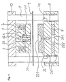
- FIG. 1 For devices which can be used according to the invention exemplary referred to Figure 1, where such a device is shown with already inserted film 1.
- she usually have a lower tool 2, the consists of a lower tool plate 21, on the one interchangeably attached die 22 is applied in the one or more mold cavities 221 are incorporated.
- the lower tool 2 can also have a plurality of dies 22 each one mold cavity 221 or more mold cavities 221 each exhibit.
- the device preferably has a hold-down device 3 for the slide 1.
- the hold-down device 3 and the stamp holding plate 5 are movable relative to one another, preferably under suspension by means of the springs 6, and that Lower tool 2 is opposite hold-down device 3 and Stamp holding plate 5 movable.
- the movement of the lower tool 2 opposite hold-down device 3 and punch holding plate 5 is effected by a drive (not in the figure shown), the electrical (e.g. as eccentric drive), can be pneumatic or hydraulic.
- the guidance of the lower tool 2 opposite the stamp holding plate 5, so that each stamp 4 fits precisely into a corresponding mold cavity 221 can be advanced is preferably so causes an upper tool plate 10 to be provided, which is immovably connected to the stamp holding plate 5 and has one or more parallel guide columns 7, the guide columns 7 when feeding the lower tool 2 towards the punch holding plate 5 in guide bushings 9 retract, which are formed in the lower tool plate 21 are.
- the axes of the guide columns 7 then also define the direction of advance of the stamps 4. the direction of advance the stamp 4 is preferred, but not mandatory perpendicular to the film 1.
- the application of compressed gas for process step c) can preferably be effected, by the stamps having 4 compressed gas supply channels 41, through which the pressurized gas is on the concave side of itself forming courtyards 11 (Fig. 4) is supplied.
- the compressed gas supply channel 41 is via a feed line 52 which in the Stamp holding plate 5 is formed with a pressurized gas source connected (not shown in the figure).
- a pressurized gas source connected (not shown in the figure).
- a hold-down seal 31 or one Stamp plate seal 51 attached for example have the shape of O-rings and those for Ensure gas tightness of the device in process step c). If a hold-down seal 31 is present, take care when the hold-down device 3 rests on the film 1, for the fact that the film 1 held more firmly at this point is used as foil 1 / hold-down in the rest of the contact surface 3, in which some mobility of the slide 1 compared to the die 22 and the hold-down device 3. This makes it easier to push the film 1 into the Steps b) and c).
- One hold-down seal 31 preferably surrounds all mold cavities 221 or alternatively, there is a separate one for each mold cavity Hold-down seal provided.
- the die 22 has in each mold cavity 221 preferably one or more vent holes 222, especially at the end of Step c) of the procedure on the convex side of the air to be displaced from the mold cavities 221 lead away.
- vent holes 222 especially at the end of Step c) of the procedure on the convex side of the air to be displaced from the mold cavities 221 lead away.
- the locking mechanism consists of at least one locking wedge 8, which is provided in the lower tool plate 21, and from at least one associated recess 71, which in one of the Guide columns 7 is incorporated.
- the position of the Recess 71 on the guide column 7 is chosen so that then the recess 71 in front of the locking wedge 8 lie when the lower tool 2 so far against the Upper tool plate 10 is advanced that the Ensemble of stamp holder plate 5 / stamp holder plate seal 51 / hold-down 3 / hold-down seal 31 / foil 1 / die 22 lies seamlessly on top of each other.
- the locking wedge 8 is inserted into the recess 71 e.g. inserted pneumatically or hydraulically so that the guide column 7 locked in the feed direction and the device is locked as a whole.
- the lower tool 2 of the stamp holding plate 5 with the stamps 4 moved away. It becomes a film 1 between the die 22 and the hold-down device 3 brought so that over all existing Mold cavities 221 slide 1 is located.
- the slide 1 can a single sheet or unwrapped portion of be an endless loop.
- the hold-down device 3 particularly preferably has one Hold-down seal 31. The hold-down seal 31 then ensures that the film 1 under the hold-down seal 31 is held more tightly than under the Rest of the hold-down device 3.
- the stamp holder plate seal 51 comes down to the hold-down 3 lie.
- the ensemble closes the stamp holding plate 5 / Stamp holder plate seal 51 / hold-down device 3 / hold-down seal 31 / foil 1 seamless.
- the locking mechanism described above is now preferred Recess 71 / locking wedge 8 activated.
- step c) is the 4 existing compressed gas supply channels 41 compressed gas to the concave Side of the emerging courtyards 11 acted, thereby this the final shape given by the mold cavities 221, forming bottom wall 11a and side wall 11b, accept.
- the one on the convex side of the emerging courtyards 11 existing air is removed by means of the ventilation holes 222 removed.
- the film layer or unwrapped portion of the film with the fully formed courtyards can be removed from the device and for example a bottling plant for the products to be packaged.
- the method according to the invention is characterized by large ratios total depth of the mold cavities / area the blister, with a thickness that is as uniform as possible Foil in the bottom and side walls of the courtyards and through one great stability of the formed film.
- the device had a stamp holding plate 5 with 2 rows of 5 stamps 4, each of which had elongated dimensions of 27.9 x 15.6 mm (length x width), with a radius of curvature at the corners of 1.2 mm.
- the base of the stamp 4 was flat.
- the stamps were made of steel with a surface roughness of R a 0.8 (N6).
- the die 22 correspondingly had 2 rows, each with 5 mold cavities 221.
- the distance between the outer edges of two mold cavities 221 was 4 mm in each case.
- the edge of each mold cavity 221 was formed as an elongated hole of 30.7 x 18.4 mm (length x width).
- the edge at the edge of the mold cavities 221 was rounded off with a radius of curvature of 0.5 mm, the curvature being continued until an angle of 57 degrees to the surface of the die 22 was reached.
- the further draft of the mold cavities 221 was designed as a series of concentric, adjoining truncated cones with an elongated (instead of circular) base, the front surface of each truncated cone forming the base of the next, smaller truncated cone.
- the parameters of the individual truncated cones were as follows: Truncated cone no. Broadside footprint (mm) Angle of inclination d. Lateral surface (degrees) 1 15.6 57 2 13.8 42 3 9.2 26 4 3.2 16
- the width of the end face of the 4th truncated cone was another 1 mm.
- the direction of movement of the stamp 4 was perpendicular to the surface of the die 22 and concentric to the corresponding mold cavity 221. Since the feed direction the stamp 4 was exactly perpendicular to the film 1, resulted the depth of the mold cavities 221 after that mentioned definition just as the vertically measured Depth of the end face of the 4th truncated cone, i.e. 7.3 mm.
- a three-layer film (60 ⁇ m PVC, 45 ⁇ m aluminum layer, 25 ⁇ m OPA) used, already, with regard on the later closure of the blister, one-sided was coated with heat seal lacquer. The temperature of the slide was approx. 20 ° C.
- a sufficiently large portion of the film to make every 10 Covering mold cavities 221 was unwound from a roll, between the die 22 and the hold-down device 3 brought and the lower tool 2 against the hold-down device 3, the punch holding plate 5 and the upper tool plate 10 raised until the hold-down 3, which is a hold-down seal 31, began to slide 1 on the die 22 to press.
- the lower tool 2 was raised further, until the end faces of the punch 4 2.8 mm into the Immerse mold cavities 221, which is approximately 38% of the total depth corresponded to the mold cavities 221.
- the stamp holding plate 5 had a stamp plate seal 51, which is in at this stage on the hold-down 3 and so the joint between hold-down device 3 and punch holding plate 5 ab participatte.
Landscapes
- Engineering & Computer Science (AREA)
- Mechanical Engineering (AREA)
- Containers And Plastic Fillers For Packaging (AREA)
- Blow-Moulding Or Thermoforming Of Plastics Or The Like (AREA)
- Basic Packing Technique (AREA)
- Auxiliary Devices For And Details Of Packaging Control (AREA)
Claims (13)
- Procédé pour la déformation à froid d'une feuille (1) pour la production d'un emballage, comprenant les phases :dans lequel les phases (b) et (c) sont exécutées sans chauffage, caractérisé en ce que, dans la phase c), la feuille (1) est chargée avec un gaz sous pression possédant une pression de plus de 20 bars.a) positionnement de la feuille (1) au-dessus d'une matrice (22) présentant au moins une cavité de moulage (221),b) enfoncement d'une partie de la feuille (1) dans la cavité de moulage (221) jusqu'à une profondeur de 95% au maximum de la profondeur totale de la cavité de moulage (221), au moyen d'un poinçon (4), de sorte qu'une bouche (11) est formée dans la feuille (1),c) charge de la bouche (11), par son côté concave, avec du gaz sous pression de manière que la feuille (1) soit pressée contre la paroi de la cavité de moulage (221),
- Procédé selon la revendication 1, caractérisé en ce que la feuille (1) est maintenue immobilisée sur la matrice (22) pendant les phases b) et c).
- Procédé selon la revendication 2, caractérisé en ce que la feuille (1) est maintenue immobilisée sur la matrice (22) au moyen d'un serre-flan (3) qui présente une garniture d'étanchéité de serre-flan (31), de telle manière que la feuille (1) soit maintenue immobilisée plus fortement sous la garniture d'étanchéité de serre-flan (31) que sous le reste du serre-flan (3).
- Procédé selon une des revendications 1 à 3, caractérisé en ce que le frottement entre la feuille (1) et le poinçon (4) et la profondeur d'enfoncement de la phase b) sont établis de telle manière qu'après la phase c), l'épaisseur de la feuille (1) soit obtenue aussi uniforme que possible dans la paroi de fond (11a) et dans la paroi latérale (11b) de la bouche (11).
- Procédé selon une des revendications 1 à 4, caractérisé en ce qu'on utilise comme feuille (1) une feuille comprenant une couche métallique.
- Procédé selon une des revendications 1 à 4, caractérisé en ce qu'on utilise comme feuille (1) une feuille métallique.
- Procédé selon une des revendications 1 à 6, caractérisé en ce que, dans la phase b), l'enfoncement d'une partie de la feuille (1) dans la cavité de moulage (221) se produit jusqu'à une profondeur de 25 à 75 % de la profondeur totale de cette cavité de moulage (221).
- Procédé selon une des revendications 1 à 7, caractérisé en ce que la feuille (1) est positionnée au-dessus de la cavité de moulage (221) à une température initiale comprise entre 10 et 30 °C et que, pendant la déformation, lors du déroulement des phases b) et c), dans le cas d'une feuille composite matière plastique/métal et dans le cas d'une feuille de matière plastique faite d'une ou de plusieurs couches de matière plastique, elle est au-dessous de la température de transition vitreuse de ces couches de matière plastique et, dans le cas où la feuille (1) est une feuille de métal, au-dessous de la température de recristallisation.
- Dispositif pour la mise en oeuvre du procédé selon la revendication 1, comprenant un outil inférieur (2) qui comporte une plaque d'outil inférieur (21) et une matrice (22) qui, à son tour, présente au moins une cavité de moulage (221) ; une plaque de support de poinçon (5) possédant au moins un poinçon (4) de telle manière que la matrice (22) et la plaque de support de poinçon (5) puissent se déplacer l'une par rapport à l'autre et que le ou les poinçons (4) plongent dans la cavité de moulage ou les cavités de moulage (221) ; des moyens pour l'amenée de gaz sous pression, de telle manière que, lorsque le poinçon (4) est enfoncé dans la cavité de moulage (221), la cavité de moulage (221) puisse être chargée avec du gaz sous pression ; des moyens pour bloquer la matrice (22) et la plaque de support de poinçon (5) dans une certaine position relative l'une par rapport à l'autre ; ainsi qu'un serre-flan (3) placé entre la plaque de support de poinçon (5) et la matrice (22), caractérisé en ce que le serre-flan est muni d'au moins une garniture d'étanchéité de serre-flan (31) présentant la forme d'une bague torique.
- Dispositif selon la revendication 9, caractérisé en ce que la plaque de support de poinçon (5) présente une garniture d'étanchéité de plaque de support de poinçon (51) qui est apte à s'appliquer sur le serre-flan (3).
- Dispositif selon la revendication 10, caractérisé en ce que la plaque de support de poinçon (5), la garniture d'étanchéité de plaque de support de poinçon (51), le serre-flan (3), la garniture d'étanchéité de serre-flan (31), la feuille (1) et la matrice (22) peuvent être serrées pour réaliser un assemblage dépourvu de jeu lors de la translation précitée de la matrice (22) et de la plaque de support de poinçon (5) l'une en direction de l'autre.
- Dispositif selon la revendication 11, caractérisé en ce quea) la plaque de support de poinçon (5) est reliée à une plaque d'outil supérieur (10) à laquelle est fixée une colonne de guidage (7) qui présente un évidement (71) à une certaine distance de la plaque d'outil supérieur (10), la colonne de guidage (7) pénétrant, lors de la translation de la matrice (22) et de la plaque de support de poinçon (5) l'une en direction de l'autre, dans une douille de guidage (9) qui est formée dans la plaque d'outil inférieure (21) et l'évidement (71) pénétrant alors aussi dans la douille de guidage (9) et un coin de verrouillage (8) qui peut se déplacer pour pénétrer dans la douille de guidage (9) étant prévu dans la plaque d'outil inférieur (21) ; etb) le coin de verrouillage (8) et l'évidement (71) forment les moyens de blocage, en ce sens que le coin de verrouillage (8) peut être enfoncé dans l'évidement (71) lorsque l'évidement (71) se trouve à l'intérieur de la douille de guidage (9).
- Procédé selon la revendication 12, caractérisé en ce que l'évidement (71) est disposé sur la colonne de guidage (7) de telle manière que le blocage soit possible lorsque la plaque de support de poinçon (5), la garniture d'étanchéité de plaque de support de poinçon (51), le serre-flan (3), la garniture d'étanchéité de serre-flan (31), la feuille (1) et la matrice (22) forment l'assemblage dépourvu de jeu.
Applications Claiming Priority (3)
| Application Number | Priority Date | Filing Date | Title |
|---|---|---|---|
| CH232199 | 1999-12-17 | ||
| CH232199 | 1999-12-17 | ||
| PCT/CH2000/000658 WO2001043947A1 (fr) | 1999-12-17 | 2000-12-11 | Procede et dispositif de fabrication d'emballages sans chauffage du film |
Publications (2)
| Publication Number | Publication Date |
|---|---|
| EP1237707A1 EP1237707A1 (fr) | 2002-09-11 |
| EP1237707B1 true EP1237707B1 (fr) | 2003-07-16 |
Family
ID=4231082
Family Applications (1)
| Application Number | Title | Priority Date | Filing Date |
|---|---|---|---|
| EP00979314A Expired - Lifetime EP1237707B1 (fr) | 1999-12-17 | 2000-12-11 | Procede et dispositif de fabrication d'emballages sans chauffage du film |
Country Status (5)
| Country | Link |
|---|---|
| EP (1) | EP1237707B1 (fr) |
| AT (1) | ATE245091T1 (fr) |
| DE (1) | DE50002940D1 (fr) |
| ES (1) | ES2202196T3 (fr) |
| WO (1) | WO2001043947A1 (fr) |
Families Citing this family (8)
| Publication number | Priority date | Publication date | Assignee | Title |
|---|---|---|---|---|
| DE102004054219B4 (de) * | 2004-11-10 | 2008-03-06 | Uhlmann Pac-Systeme Gmbh & Co Kg | Vorrichtung zum Tiefziehen thermoformbarer Folie |
| DE102011006797B4 (de) | 2011-04-05 | 2022-04-28 | Friedrich-Alexander-Universität Erlangen-Nürnberg | Verfahren zur Herstellung eines faserverstärkten Kunststoffteils aus mindestens einem plattenförmigen Halbzeug aus einer mit Endlosfasern verstärkten thermoplastischen Matrix |
| DE102013203829B4 (de) * | 2013-03-06 | 2015-07-23 | Leibniz-Institut für Oberflächenmodifizierung e.V. | Verfahren und Vorrichtung zur Herstellung beidseitig mikrostrukturierter Verbundfolien |
| ITBO20130700A1 (it) * | 2013-12-20 | 2015-06-21 | Comi S P A | Dispositivo per la termoformatura di lastre in materiale plastico |
| KR101773803B1 (ko) | 2015-12-29 | 2017-09-12 | 주식회사 성우하이텍 | 멀티 성형 방법 |
| CN108454122A (zh) * | 2018-02-06 | 2018-08-28 | 濉溪县伊索工贸有限公司 | 一种饰品滚珠机 |
| DE102020101088A1 (de) | 2020-01-17 | 2021-07-22 | Volkswagen Aktiengesellschaft | Verfahren zur Umformung von Metallverbundfolien für Batteriezellen |
| CN116922677B (zh) * | 2023-07-31 | 2025-11-11 | 昆山贝松精密电子有限公司 | 一种网布线外成形机构 |
Family Cites Families (5)
| Publication number | Priority date | Publication date | Assignee | Title |
|---|---|---|---|---|
| US3600753A (en) * | 1969-09-29 | 1971-08-24 | Koehring Co | Differential pressure forming mold assembly for forming plastic articles in a thermoplastic web |
| CH633203A5 (de) * | 1978-03-31 | 1982-11-30 | Alusuisse | Verfahren und vorrichtung zum herstellen einer verpackungsmulde in einer metall-kunststoffverbundfolie. |
| US4563325A (en) * | 1983-05-20 | 1986-01-07 | Shell Oil Company | Forming plastic articles in solid state |
| DE59606545D1 (de) * | 1995-12-12 | 2001-04-12 | Alusuisse Tech & Man Ag | Verfahren zum Herstellen von Blisterverpackungen |
| EP1023985A1 (fr) * | 1999-01-27 | 2000-08-02 | Alusuisse Technology & Management AG | Procédé et appareil pour le formage d'emballages déformés à froid |
-
2000
- 2000-12-11 AT AT00979314T patent/ATE245091T1/de not_active IP Right Cessation
- 2000-12-11 WO PCT/CH2000/000658 patent/WO2001043947A1/fr not_active Ceased
- 2000-12-11 DE DE50002940T patent/DE50002940D1/de not_active Expired - Fee Related
- 2000-12-11 EP EP00979314A patent/EP1237707B1/fr not_active Expired - Lifetime
- 2000-12-11 ES ES00979314T patent/ES2202196T3/es not_active Expired - Lifetime
Also Published As
| Publication number | Publication date |
|---|---|
| DE50002940D1 (de) | 2003-08-21 |
| ES2202196T3 (es) | 2004-04-01 |
| EP1237707A1 (fr) | 2002-09-11 |
| ATE245091T1 (de) | 2003-08-15 |
| WO2001043947A1 (fr) | 2001-06-21 |
Similar Documents
| Publication | Publication Date | Title |
|---|---|---|
| DE3228170C2 (de) | Verfahren zur Herstellung von Sandwich-Gebilden | |
| DE3925746C2 (de) | Verfahren und Vorrichtung zum Herstellen einer wiederverschließbaren Packung | |
| DE4325203C2 (de) | Vorrichtung und Verfahren zur Herstellung von keramischen Mehrlagenschaltungen | |
| DE69513121T2 (de) | Verfahren zur Herstellung von thermoplastischen Kunststoffformteilen | |
| WO1997021534A1 (fr) | Procede de production d'emballage façonne | |
| EP0718077A1 (fr) | Procédé et dispositifs pour perforer des surfaces lisses à cellules fermées de feuilles en mousse à cellules ouvertes | |
| DE1479343A1 (de) | Verfahren und Vorrichtung zum Tiefziehen | |
| CH622191A5 (en) | Method for the production of a metallic laminar structure | |
| EP0305714A2 (fr) | Dispositif pour mouler des objets dans un matériau thermoplastique | |
| EP0987094A2 (fr) | Dispositif pour réaliser des emballages | |
| EP1237707B1 (fr) | Procede et dispositif de fabrication d'emballages sans chauffage du film | |
| CH633203A5 (de) | Verfahren und vorrichtung zum herstellen einer verpackungsmulde in einer metall-kunststoffverbundfolie. | |
| EP0710176B1 (fr) | Procede et dispositif de production de sachets | |
| DE7826241U1 (de) | Vorrichtung zum herstellen von verpackungsmulden mit hoher sperrwirkung in einer aus der dehnung tiefziehfaehigen metall/kunststoff-verbundfolie | |
| EP1392480B1 (fr) | Procede de fabrication d'un corps tridimensionnel a forme conferee par deformation | |
| EP0557614A1 (fr) | Procédé de soudage de feuilles thermoplastiques sans halogènes | |
| DE1283587B (de) | Verfahren zum Einschmelzen von Tragbandverstaerkungen unter gleichzeitiger Ausbildung der Endglieder bei Reissverschluessen | |
| EP0371392A2 (fr) | Dispositif d'emboutissage de feuilles devant mousser sous d'effet de la chaleur | |
| DE69229912T2 (de) | Vorrichtung zum präzisionsverformen, verfahren und artikel | |
| DE19522805C2 (de) | Vorrichtung und Verfahren zum Kaltverformen eines Metall/Kunststoff-Verbundes zu einer Formpackung | |
| DE2620795C2 (fr) | ||
| DE4340381A1 (de) | Verfahren und Vorrichtung zum Verformen und Verschließen der Ränder von Hohlkammerplatten aus einem thermoplastischen Material | |
| EP4442437A1 (fr) | Poste de scellage pour une machine d'emballage et procédé de scellage | |
| DE102006004436A1 (de) | Werkzeug zum superplastischen Umformen | |
| EP0373395A2 (fr) | Procédé et dispositif pour la mise en forme d'un article en forme de récipient à partir d'une feuille |
Legal Events
| Date | Code | Title | Description |
|---|---|---|---|
| PUAI | Public reference made under article 153(3) epc to a published international application that has entered the european phase |
Free format text: ORIGINAL CODE: 0009012 |
|
| 17P | Request for examination filed |
Effective date: 20020601 |
|
| AK | Designated contracting states |
Kind code of ref document: A1 Designated state(s): AT BE CH CY DE DK ES FI FR GB GR IE IT LI LU MC NL PT SE TR |
|
| GRAH | Despatch of communication of intention to grant a patent |
Free format text: ORIGINAL CODE: EPIDOS IGRA |
|
| RIC1 | Information provided on ipc code assigned before grant |
Ipc: 7B 29C 51/38 B Ipc: 7B 21D 26:02 Z Ipc: 7B 29C 51/04 A Ipc: 7B 29C 51/14 B Ipc: 7B 29C 67/00 B |
|
| RTI1 | Title (correction) |
Free format text: METHOD AND DEVICE FOR PRODUCING PACKINGS WITHOUT HEATING THE FILM |
|
| GRAH | Despatch of communication of intention to grant a patent |
Free format text: ORIGINAL CODE: EPIDOS IGRA |
|
| GRAA | (expected) grant |
Free format text: ORIGINAL CODE: 0009210 |
|
| AK | Designated contracting states |
Designated state(s): AT BE CH CY DE DK ES FI FR GB GR IE IT LI LU MC NL PT SE TR |
|
| PG25 | Lapsed in a contracting state [announced via postgrant information from national office to epo] |
Ref country code: TR Free format text: LAPSE BECAUSE OF FAILURE TO SUBMIT A TRANSLATION OF THE DESCRIPTION OR TO PAY THE FEE WITHIN THE PRESCRIBED TIME-LIMIT Effective date: 20030716 Ref country code: FI Free format text: LAPSE BECAUSE OF FAILURE TO SUBMIT A TRANSLATION OF THE DESCRIPTION OR TO PAY THE FEE WITHIN THE PRESCRIBED TIME-LIMIT Effective date: 20030716 Ref country code: NL Free format text: LAPSE BECAUSE OF FAILURE TO SUBMIT A TRANSLATION OF THE DESCRIPTION OR TO PAY THE FEE WITHIN THE PRESCRIBED TIME-LIMIT Effective date: 20030716 Ref country code: IE Free format text: LAPSE BECAUSE OF FAILURE TO SUBMIT A TRANSLATION OF THE DESCRIPTION OR TO PAY THE FEE WITHIN THE PRESCRIBED TIME-LIMIT Effective date: 20030716 |
|
| REG | Reference to a national code |
Ref country code: GB Ref legal event code: FG4D Free format text: NOT ENGLISH |
|
| REG | Reference to a national code |
Ref country code: CH Ref legal event code: EP |
|
| REG | Reference to a national code |
Ref country code: CH Ref legal event code: NV Representative=s name: A. BRAUN, BRAUN, HERITIER, ESCHMANN AG PATENTANWAE |
|
| REG | Reference to a national code |
Ref country code: IE Ref legal event code: FG4D Free format text: GERMAN |
|
| REF | Corresponds to: |
Ref document number: 50002940 Country of ref document: DE Date of ref document: 20030821 Kind code of ref document: P |
|
| PG25 | Lapsed in a contracting state [announced via postgrant information from national office to epo] |
Ref country code: DK Free format text: LAPSE BECAUSE OF FAILURE TO SUBMIT A TRANSLATION OF THE DESCRIPTION OR TO PAY THE FEE WITHIN THE PRESCRIBED TIME-LIMIT Effective date: 20031016 Ref country code: SE Free format text: LAPSE BECAUSE OF FAILURE TO SUBMIT A TRANSLATION OF THE DESCRIPTION OR TO PAY THE FEE WITHIN THE PRESCRIBED TIME-LIMIT Effective date: 20031016 Ref country code: GR Free format text: LAPSE BECAUSE OF FAILURE TO SUBMIT A TRANSLATION OF THE DESCRIPTION OR TO PAY THE FEE WITHIN THE PRESCRIBED TIME-LIMIT Effective date: 20031016 |
|
| NLV1 | Nl: lapsed or annulled due to failure to fulfill the requirements of art. 29p and 29m of the patents act | ||
| GBT | Gb: translation of ep patent filed (gb section 77(6)(a)/1977) |
Effective date: 20031117 |
|
| PG25 | Lapsed in a contracting state [announced via postgrant information from national office to epo] |
Ref country code: CY Free format text: LAPSE BECAUSE OF FAILURE TO SUBMIT A TRANSLATION OF THE DESCRIPTION OR TO PAY THE FEE WITHIN THE PRESCRIBED TIME-LIMIT Effective date: 20031211 Ref country code: AT Free format text: LAPSE BECAUSE OF NON-PAYMENT OF DUE FEES Effective date: 20031211 Ref country code: LU Free format text: LAPSE BECAUSE OF NON-PAYMENT OF DUE FEES Effective date: 20031211 |
|
| PG25 | Lapsed in a contracting state [announced via postgrant information from national office to epo] |
Ref country code: PT Free format text: LAPSE BECAUSE OF FAILURE TO SUBMIT A TRANSLATION OF THE DESCRIPTION OR TO PAY THE FEE WITHIN THE PRESCRIBED TIME-LIMIT Effective date: 20031216 |
|
| PG25 | Lapsed in a contracting state [announced via postgrant information from national office to epo] |
Ref country code: BE Free format text: LAPSE BECAUSE OF NON-PAYMENT OF DUE FEES Effective date: 20031231 Ref country code: MC Free format text: LAPSE BECAUSE OF NON-PAYMENT OF DUE FEES Effective date: 20031231 |
|
| REG | Reference to a national code |
Ref country code: IE Ref legal event code: FD4D |
|
| REG | Reference to a national code |
Ref country code: ES Ref legal event code: FG2A Ref document number: 2202196 Country of ref document: ES Kind code of ref document: T3 |
|
| ET | Fr: translation filed | ||
| PLBE | No opposition filed within time limit |
Free format text: ORIGINAL CODE: 0009261 |
|
| STAA | Information on the status of an ep patent application or granted ep patent |
Free format text: STATUS: NO OPPOSITION FILED WITHIN TIME LIMIT |
|
| BERE | Be: lapsed |
Owner name: *ROHRER A.G. Effective date: 20031231 |
|
| 26N | No opposition filed |
Effective date: 20040419 |
|
| REG | Reference to a national code |
Ref country code: CH Ref legal event code: PFA Owner name: ROHRER AG Free format text: ROHRER AG#BREMENSTALLSTRASSE 1#4313 MOEHLIN (CH) -TRANSFER TO- ROHRER AG#BREMENSTALLSTRASSE 1#4313 MOEHLIN (CH) |
|
| PGFP | Annual fee paid to national office [announced via postgrant information from national office to epo] |
Ref country code: CH Payment date: 20081222 Year of fee payment: 9 |
|
| PGFP | Annual fee paid to national office [announced via postgrant information from national office to epo] |
Ref country code: ES Payment date: 20081204 Year of fee payment: 9 |
|
| PGFP | Annual fee paid to national office [announced via postgrant information from national office to epo] |
Ref country code: IT Payment date: 20081215 Year of fee payment: 9 |
|
| PGFP | Annual fee paid to national office [announced via postgrant information from national office to epo] |
Ref country code: DE Payment date: 20090227 Year of fee payment: 9 |
|
| PGFP | Annual fee paid to national office [announced via postgrant information from national office to epo] |
Ref country code: GB Payment date: 20081202 Year of fee payment: 9 |
|
| PGFP | Annual fee paid to national office [announced via postgrant information from national office to epo] |
Ref country code: FR Payment date: 20081211 Year of fee payment: 9 |
|
| REG | Reference to a national code |
Ref country code: CH Ref legal event code: PL |
|
| GBPC | Gb: european patent ceased through non-payment of renewal fee |
Effective date: 20091211 |
|
| REG | Reference to a national code |
Ref country code: FR Ref legal event code: ST Effective date: 20100831 |
|
| PG25 | Lapsed in a contracting state [announced via postgrant information from national office to epo] |
Ref country code: LI Free format text: LAPSE BECAUSE OF NON-PAYMENT OF DUE FEES Effective date: 20091231 Ref country code: FR Free format text: LAPSE BECAUSE OF NON-PAYMENT OF DUE FEES Effective date: 20091231 Ref country code: CH Free format text: LAPSE BECAUSE OF NON-PAYMENT OF DUE FEES Effective date: 20091231 |
|
| PG25 | Lapsed in a contracting state [announced via postgrant information from national office to epo] |
Ref country code: DE Free format text: LAPSE BECAUSE OF NON-PAYMENT OF DUE FEES Effective date: 20100701 |
|
| PG25 | Lapsed in a contracting state [announced via postgrant information from national office to epo] |
Ref country code: GB Free format text: LAPSE BECAUSE OF NON-PAYMENT OF DUE FEES Effective date: 20091211 |
|
| PG25 | Lapsed in a contracting state [announced via postgrant information from national office to epo] |
Ref country code: IT Free format text: LAPSE BECAUSE OF NON-PAYMENT OF DUE FEES Effective date: 20091211 |
|
| REG | Reference to a national code |
Ref country code: ES Ref legal event code: FD2A Effective date: 20110406 |
|
| PG25 | Lapsed in a contracting state [announced via postgrant information from national office to epo] |
Ref country code: ES Free format text: LAPSE BECAUSE OF NON-PAYMENT OF DUE FEES Effective date: 20110324 |
|
| PG25 | Lapsed in a contracting state [announced via postgrant information from national office to epo] |
Ref country code: ES Free format text: LAPSE BECAUSE OF NON-PAYMENT OF DUE FEES Effective date: 20091212 |