EP1237679B1 - Schleifoberfläche und -artikel und deren hestellungsverfahren - Google Patents
Schleifoberfläche und -artikel und deren hestellungsverfahren Download PDFInfo
- Publication number
- EP1237679B1 EP1237679B1 EP00986502A EP00986502A EP1237679B1 EP 1237679 B1 EP1237679 B1 EP 1237679B1 EP 00986502 A EP00986502 A EP 00986502A EP 00986502 A EP00986502 A EP 00986502A EP 1237679 B1 EP1237679 B1 EP 1237679B1
- Authority
- EP
- European Patent Office
- Prior art keywords
- mask
- carrier
- particles
- hard particles
- hard
- Prior art date
- Legal status (The legal status is an assumption and is not a legal conclusion. Google has not performed a legal analysis and makes no representation as to the accuracy of the status listed.)
- Expired - Lifetime
Links
- 238000000034 method Methods 0.000 title claims abstract description 89
- 239000002245 particle Substances 0.000 claims abstract description 259
- 239000000463 material Substances 0.000 claims abstract description 162
- 239000011159 matrix material Substances 0.000 claims abstract description 62
- 239000003082 abrasive agent Substances 0.000 claims abstract description 30
- 238000010438 heat treatment Methods 0.000 claims abstract description 24
- 230000014759 maintenance of location Effects 0.000 claims description 53
- 230000001070 adhesive effect Effects 0.000 claims description 29
- 239000000853 adhesive Substances 0.000 claims description 28
- 230000000153 supplemental effect Effects 0.000 claims description 22
- 239000011248 coating agent Substances 0.000 claims description 7
- 238000000576 coating method Methods 0.000 claims description 7
- 239000004820 Pressure-sensitive adhesive Substances 0.000 claims description 5
- 239000000155 melt Substances 0.000 claims description 5
- 239000002390 adhesive tape Substances 0.000 claims 1
- 230000008569 process Effects 0.000 description 35
- 238000005245 sintering Methods 0.000 description 35
- 239000000843 powder Substances 0.000 description 27
- 239000000758 substrate Substances 0.000 description 15
- 230000001413 cellular effect Effects 0.000 description 14
- 238000005056 compaction Methods 0.000 description 14
- 239000000203 mixture Substances 0.000 description 14
- 239000000126 substance Substances 0.000 description 13
- 238000000926 separation method Methods 0.000 description 10
- PXHVJJICTQNCMI-UHFFFAOYSA-N Nickel Chemical compound [Ni] PXHVJJICTQNCMI-UHFFFAOYSA-N 0.000 description 9
- 230000008595 infiltration Effects 0.000 description 9
- 238000001764 infiltration Methods 0.000 description 9
- 239000007791 liquid phase Substances 0.000 description 9
- 238000012545 processing Methods 0.000 description 9
- 239000000956 alloy Substances 0.000 description 8
- 229910045601 alloy Inorganic materials 0.000 description 8
- 239000011888 foil Substances 0.000 description 8
- 229910052751 metal Inorganic materials 0.000 description 8
- 239000002184 metal Substances 0.000 description 8
- 239000002356 single layer Substances 0.000 description 8
- 239000002131 composite material Substances 0.000 description 6
- 238000005520 cutting process Methods 0.000 description 6
- 238000000151 deposition Methods 0.000 description 6
- 150000002739 metals Chemical class 0.000 description 6
- 239000011148 porous material Substances 0.000 description 6
- 239000011343 solid material Substances 0.000 description 6
- XEEYBQQBJWHFJM-UHFFFAOYSA-N Iron Chemical compound [Fe] XEEYBQQBJWHFJM-UHFFFAOYSA-N 0.000 description 5
- 238000005219 brazing Methods 0.000 description 5
- 229910052804 chromium Inorganic materials 0.000 description 5
- 239000011651 chromium Substances 0.000 description 5
- 239000000835 fiber Substances 0.000 description 5
- 239000007788 liquid Substances 0.000 description 5
- 238000004519 manufacturing process Methods 0.000 description 5
- 229910052759 nickel Inorganic materials 0.000 description 5
- VYZAMTAEIAYCRO-UHFFFAOYSA-N Chromium Chemical compound [Cr] VYZAMTAEIAYCRO-UHFFFAOYSA-N 0.000 description 4
- 230000009471 action Effects 0.000 description 4
- 238000009826 distribution Methods 0.000 description 4
- 239000000945 filler Substances 0.000 description 4
- 239000011521 glass Substances 0.000 description 4
- 230000035515 penetration Effects 0.000 description 4
- 230000000717 retained effect Effects 0.000 description 4
- 239000007787 solid Substances 0.000 description 4
- RTAQQCXQSZGOHL-UHFFFAOYSA-N Titanium Chemical compound [Ti] RTAQQCXQSZGOHL-UHFFFAOYSA-N 0.000 description 3
- HCHKCACWOHOZIP-UHFFFAOYSA-N Zinc Chemical compound [Zn] HCHKCACWOHOZIP-UHFFFAOYSA-N 0.000 description 3
- 239000000654 additive Substances 0.000 description 3
- 229910052796 boron Inorganic materials 0.000 description 3
- 229910017052 cobalt Inorganic materials 0.000 description 3
- 239000010941 cobalt Substances 0.000 description 3
- GUTLYIVDDKVIGB-UHFFFAOYSA-N cobalt atom Chemical compound [Co] GUTLYIVDDKVIGB-UHFFFAOYSA-N 0.000 description 3
- 238000005530 etching Methods 0.000 description 3
- 238000011049 filling Methods 0.000 description 3
- 238000000227 grinding Methods 0.000 description 3
- 238000005552 hardfacing Methods 0.000 description 3
- 229910052742 iron Inorganic materials 0.000 description 3
- 238000011068 loading method Methods 0.000 description 3
- 239000007769 metal material Substances 0.000 description 3
- 230000004048 modification Effects 0.000 description 3
- 238000012986 modification Methods 0.000 description 3
- 239000011368 organic material Substances 0.000 description 3
- 239000004033 plastic Substances 0.000 description 3
- 229920003023 plastic Polymers 0.000 description 3
- 230000001681 protective effect Effects 0.000 description 3
- 238000004080 punching Methods 0.000 description 3
- 230000009467 reduction Effects 0.000 description 3
- 239000012779 reinforcing material Substances 0.000 description 3
- 239000011347 resin Substances 0.000 description 3
- 229920005989 resin Polymers 0.000 description 3
- 239000010936 titanium Substances 0.000 description 3
- 229910052719 titanium Inorganic materials 0.000 description 3
- 229910052725 zinc Inorganic materials 0.000 description 3
- 239000011701 zinc Substances 0.000 description 3
- ZOXJGFHDIHLPTG-UHFFFAOYSA-N Boron Chemical compound [B] ZOXJGFHDIHLPTG-UHFFFAOYSA-N 0.000 description 2
- 239000004593 Epoxy Substances 0.000 description 2
- VYPSYNLAJGMNEJ-UHFFFAOYSA-N Silicium dioxide Chemical compound O=[Si]=O VYPSYNLAJGMNEJ-UHFFFAOYSA-N 0.000 description 2
- 229910000831 Steel Inorganic materials 0.000 description 2
- 239000000969 carrier Substances 0.000 description 2
- 239000000919 ceramic Substances 0.000 description 2
- 238000007906 compression Methods 0.000 description 2
- 230000006835 compression Effects 0.000 description 2
- 229910052802 copper Inorganic materials 0.000 description 2
- 239000010949 copper Substances 0.000 description 2
- 238000013461 design Methods 0.000 description 2
- 239000010432 diamond Substances 0.000 description 2
- 238000009792 diffusion process Methods 0.000 description 2
- 238000005553 drilling Methods 0.000 description 2
- 229920001971 elastomer Polymers 0.000 description 2
- 239000002657 fibrous material Substances 0.000 description 2
- 239000003292 glue Substances 0.000 description 2
- 230000005484 gravity Effects 0.000 description 2
- 230000006698 induction Effects 0.000 description 2
- 230000005415 magnetization Effects 0.000 description 2
- 239000012768 molten material Substances 0.000 description 2
- 238000000465 moulding Methods 0.000 description 2
- 230000000737 periodic effect Effects 0.000 description 2
- 239000005060 rubber Substances 0.000 description 2
- 230000003068 static effect Effects 0.000 description 2
- 239000010959 steel Substances 0.000 description 2
- 239000004753 textile Substances 0.000 description 2
- 238000007751 thermal spraying Methods 0.000 description 2
- 239000010409 thin film Substances 0.000 description 2
- 229910052721 tungsten Inorganic materials 0.000 description 2
- XLYOFNOQVPJJNP-UHFFFAOYSA-N water Substances O XLYOFNOQVPJJNP-UHFFFAOYSA-N 0.000 description 2
- 238000003466 welding Methods 0.000 description 2
- 229910052582 BN Inorganic materials 0.000 description 1
- PZNSFCLAULLKQX-UHFFFAOYSA-N Boron nitride Chemical compound N#B PZNSFCLAULLKQX-UHFFFAOYSA-N 0.000 description 1
- 229910000906 Bronze Inorganic materials 0.000 description 1
- RYGMFSIKBFXOCR-UHFFFAOYSA-N Copper Chemical compound [Cu] RYGMFSIKBFXOCR-UHFFFAOYSA-N 0.000 description 1
- ZOKXTWBITQBERF-UHFFFAOYSA-N Molybdenum Chemical compound [Mo] ZOKXTWBITQBERF-UHFFFAOYSA-N 0.000 description 1
- 229910003271 Ni-Fe Inorganic materials 0.000 description 1
- BQCADISMDOOEFD-UHFFFAOYSA-N Silver Chemical compound [Ag] BQCADISMDOOEFD-UHFFFAOYSA-N 0.000 description 1
- 239000006061 abrasive grain Substances 0.000 description 1
- 230000000996 additive effect Effects 0.000 description 1
- 238000004026 adhesive bonding Methods 0.000 description 1
- 239000012790 adhesive layer Substances 0.000 description 1
- 238000004873 anchoring Methods 0.000 description 1
- 239000011324 bead Substances 0.000 description 1
- 239000011230 binding agent Substances 0.000 description 1
- 238000005422 blasting Methods 0.000 description 1
- 238000007664 blowing Methods 0.000 description 1
- 239000010974 bronze Substances 0.000 description 1
- 230000001680 brushing effect Effects 0.000 description 1
- 239000012876 carrier material Substances 0.000 description 1
- 238000005266 casting Methods 0.000 description 1
- 230000008859 change Effects 0.000 description 1
- 239000011247 coating layer Substances 0.000 description 1
- 230000002301 combined effect Effects 0.000 description 1
- 150000001875 compounds Chemical class 0.000 description 1
- 238000007596 consolidation process Methods 0.000 description 1
- 238000000354 decomposition reaction Methods 0.000 description 1
- 230000005347 demagnetization Effects 0.000 description 1
- 238000007599 discharging Methods 0.000 description 1
- 239000000428 dust Substances 0.000 description 1
- 238000010410 dusting Methods 0.000 description 1
- 230000005611 electricity Effects 0.000 description 1
- 238000009713 electroplating Methods 0.000 description 1
- 125000003700 epoxy group Chemical group 0.000 description 1
- 150000002148 esters Chemical class 0.000 description 1
- 239000010408 film Substances 0.000 description 1
- 238000010304 firing Methods 0.000 description 1
- 230000004907 flux Effects 0.000 description 1
- 230000004927 fusion Effects 0.000 description 1
- 239000007789 gas Substances 0.000 description 1
- 239000000499 gel Substances 0.000 description 1
- -1 i.e. Substances 0.000 description 1
- 229910052500 inorganic mineral Inorganic materials 0.000 description 1
- 230000010354 integration Effects 0.000 description 1
- 229910052746 lanthanum Inorganic materials 0.000 description 1
- 239000010410 layer Substances 0.000 description 1
- 229910052748 manganese Inorganic materials 0.000 description 1
- 239000011572 manganese Substances 0.000 description 1
- WPBNNNQJVZRUHP-UHFFFAOYSA-L manganese(2+);methyl n-[[2-(methoxycarbonylcarbamothioylamino)phenyl]carbamothioyl]carbamate;n-[2-(sulfidocarbothioylamino)ethyl]carbamodithioate Chemical compound [Mn+2].[S-]C(=S)NCCNC([S-])=S.COC(=O)NC(=S)NC1=CC=CC=C1NC(=S)NC(=O)OC WPBNNNQJVZRUHP-UHFFFAOYSA-L 0.000 description 1
- 230000008018 melting Effects 0.000 description 1
- 238000002844 melting Methods 0.000 description 1
- 150000001247 metal acetylides Chemical class 0.000 description 1
- 239000011707 mineral Substances 0.000 description 1
- 229910052750 molybdenum Inorganic materials 0.000 description 1
- 239000011733 molybdenum Substances 0.000 description 1
- 150000004767 nitrides Chemical class 0.000 description 1
- 238000009828 non-uniform distribution Methods 0.000 description 1
- 230000003647 oxidation Effects 0.000 description 1
- 238000007254 oxidation reaction Methods 0.000 description 1
- 238000012856 packing Methods 0.000 description 1
- 230000036961 partial effect Effects 0.000 description 1
- 239000006072 paste Substances 0.000 description 1
- 239000012071 phase Substances 0.000 description 1
- 238000007747 plating Methods 0.000 description 1
- 238000005498 polishing Methods 0.000 description 1
- 229920000647 polyepoxide Polymers 0.000 description 1
- 238000011084 recovery Methods 0.000 description 1
- 238000006722 reduction reaction Methods 0.000 description 1
- 230000000284 resting effect Effects 0.000 description 1
- 229910052702 rhenium Inorganic materials 0.000 description 1
- 238000007788 roughening Methods 0.000 description 1
- 238000010079 rubber tapping Methods 0.000 description 1
- 238000007790 scraping Methods 0.000 description 1
- 239000000377 silicon dioxide Substances 0.000 description 1
- 229910052709 silver Inorganic materials 0.000 description 1
- 239000004332 silver Substances 0.000 description 1
- 239000002002 slurry Substances 0.000 description 1
- 239000007921 spray Substances 0.000 description 1
- 238000009718 spray deposition Methods 0.000 description 1
- 238000005507 spraying Methods 0.000 description 1
- 230000003746 surface roughness Effects 0.000 description 1
- 229920002994 synthetic fiber Polymers 0.000 description 1
- 238000002207 thermal evaporation Methods 0.000 description 1
- 239000011366 tin-based material Substances 0.000 description 1
- WFKWXMTUELFFGS-UHFFFAOYSA-N tungsten Chemical compound [W] WFKWXMTUELFFGS-UHFFFAOYSA-N 0.000 description 1
- 239000010937 tungsten Substances 0.000 description 1
- 238000009827 uniform distribution Methods 0.000 description 1
- 238000007740 vapor deposition Methods 0.000 description 1
- 238000004073 vulcanization Methods 0.000 description 1
- 229910052727 yttrium Inorganic materials 0.000 description 1
Images


Classifications
-
- B—PERFORMING OPERATIONS; TRANSPORTING
- B24—GRINDING; POLISHING
- B24D—TOOLS FOR GRINDING, BUFFING OR SHARPENING
- B24D11/00—Constructional features of flexible abrasive materials; Special features in the manufacture of such materials
Definitions
- This invention relates generally to abrasive and wear resistant surfaces and articles comprising these surfaces. More specifically, it discloses new and improved methods for obtaining such surfaces containing non-randomly distributed hard particles that provide abrasive and wear resistant quality to the surfaces. An example of such a method is disclosed in US 5,380 , 390 which is considered to be the closest state of the art.
- the mask may take a form of a mesh or other cellular material that is placed against the substrate before contacting the substrate with the hard particles. The mask will then determine the distribution of the hard particles and/or zones or clusters of the particles according to the openings of the mesh or other cellular material. Further, the mask can be removed prior to heating or left to become an integral part of the abrasive material.
- the substrate can be a preform of sinterable matrix material and the hard particles can be urged or compacted into it with various compressing means, such as roll compaction of the pre-positioned hard particles before sintering of the material.
- the matrix material can be a sinterable or fusible material and can be deposited by a temperature related process such as thermal (e.g., plasma) spray or vapor deposition, thermal deposition of material being considered an equivalent of sinterable material.
- the matrix material may also be impregnated with a fusible material by placing a fusible material on at least one side of the assembly before beginning the heating/or compaction, the fusible material melting during heating and being carried into the matrix material by capillary action.
- U.S. Patent No. 5,620,489 discloses a sinterable matrix material in the form of a soft, easy deformable and flexible preform made from a mixture of a quantity of powdered sinterable matrix material and a liquid binder composition.
- a plurality of abrasive particles can then be included at least partially in the preform which is then sintered to form an abrasive article.
- the binder-powder mixture can be dispensed onto a support surface, and doctored to uniform thickness by a doctor blade for forming the preform.
- the plurality of abrasive particles can be included in the perform, e.g., by placing the particles on at least one side of the preform and then urging the particles into the preform.
- the abrasive particles can be urged into the preform before the preform is sintered or during sintering. Moreover, the particles can be included in the preform in a random manner or in a non-random manner that can be defined by a cellular type mesh or mask material.
- U.S. Patent No. 5,791,330 relates to similar abrasive materials having a non-random distribution of abrasive particles and teaches that the mesh material, after being used to position the abrasive particles, may be partially or completely removed either physically prior to sintering the matrix material, or dissolved or evaporated at the temperature used to sinter the matrix material leaving the abrasive particles uniformly distributed within matrix material.
- structural members can be positioned between or at least on one side of the matrix material, abrasive particles, and mesh materials and can be of metallic or non-metallic compounds, powder, fibers, meshes, shims, foils and any combinations thereof.
- composition of the structural members can be different from the composition of the matrix material and they can be sintered or brazed, preferably under pressure, to the sintered abrasive material.
- the patent also discloses as suitable sinterable matrix materials or a component of sinterable matrix materials, compositions comprising carbide forming elements, such as boron, chromium, iron with zinc and without zinc and that braising and fusing materials can be used as additives with the compositions.
- the present invention provides a new and improved method for making articles, including but not limited to abrasive and wear resistant articles containing hard, abrasive particles distributed in a desired, preferably non-random or non-uniform pattern in the articles that is more suitable for mechanization, automation, and mass production.
- the process of the invention comprises selecting at least one mask, (e.g., a stencil, template, cellular type material, mesh, etc.) having openings therein and placing it against or assembling it with a carrier or substrate capable of supporting or carrying temporarily and/or permanently at least some of the hard particles.
- a mask e.g., a stencil, template, cellular type material, mesh, etc.
- the assembly of the mask and the carrier then receives a quantity of the hard particles, some of which go through the openings of the mask and are fixed to or rest on the carrier and another portion of which go onto the mask and rest on the spaces of the mask between the openings.
- the outer surface of the mask opposite the surface adjacent the carrier is provided with affixing means to which the particles will adhere to hold the particles on the spaces on the outer surface of the mask. Then, the mask having the hard particles adhered thereto is separated from the carrier, the separated mask thereby effectively and efficiently removing the plurality of hard particles that will not form a part of the final abrasive product.
- the hard particles are distributed on the carrier according to the design of the mask primarily according to the size, shape and distribution of the openings of the mask as well as by the size and shape of the hard particles. Thus a programmed or non-random distribution of the hard particles is provided on the carrier.
- the support or temporary retention of the hard particles on the carrier can be provided by the characteristics of the carrier and/or the hard particles as well as the surface characteristics of the carrier or hard particles, such as coating materials applied to the carrier and/or hard particles, moisture content, humidity, weight, (utilization of gravity temperature) temperature (e.g., negative temperature), magnetization, static electricity, discharge conditions, etc.
- coating materials applied to the carrier and/or hard particles such as coating materials applied to the carrier and/or hard particles, moisture content, humidity, weight, (utilization of gravity temperature) temperature (e.g., negative temperature), magnetization, static electricity, discharge conditions, etc.
- further substances can be applied to more permanently affix the particles to the carrier.
- the mask can be removed from the carrier before, during, or after such fixing of the hard particles to the carrier. Removal of the mask during, simultaneously or immediately after the process of fixing constitutes the most preferred embodiments of this invention.
- the hard particles adhered thereto are preferably separated from the mask, recovered, and then utilized again for making further abrasive materials.
- Means for affixing the hard particles to the mask and also to each other if desired include an adhesive coating on the mask or anchoring through surface roughness. Also available are masks made from a substance that is inherently tacky. However, any means that holds the particles to the outer surface of the mask so that they are removed when the mask is separated from the carrier is acceptable.
- the hard particles that are not affixed to the mask and/or the carrier and/or to each other are removed from the carrier and the mask or their assembly, forming a further plurality of the hard particles that can be collected and utilized again for making abrasive materials.
- These hard particles can be removed by any suitable method including, but not limited to, utilization of gravity, brushing, blowing, blasting, picking, suctioning, vacuum, scraping, shacking, tapping, vibrating, heating, magnetization, demagnetization, electrical charging and discharging.
- This processing can include at least one or more of the following:
- the hard particles are permanently (for the life of the hard particles in the abrasive tool) fixed or bonded in the retaining matrix and/or to the carrier and optionally to each other.
- Figures 1 and 2 show examples of masks having openings suitable for use in the present invention that can be templates, stencils, cellular materials, or mesh materials. These masks can be made by many ways, including but not limited to perforation, drilling, cutting, braising, welding and gluing, or by laser.
- Mask 10, shown in Figure 1 comprises a plurality of through openings 15-24, each of which is different.
- Mask 30, shown in Figure 2 shows a plurality of round openings 35 and a plurality of polygon openings 40.
- Figure 3 is a cross section of an assembly of a mask 50, similar to mask 10 or 30, having through openings 55 and mask sections 57 between the through openings 55, resting on a carrier 60.
- the side of the mask remote from the carrier is provided with affixing means, such as a coating of adhesive 100, to which the particles will adhere.
- affixing means such as a coating of adhesive 100
- the mask could be made of an inherently tacky substance or become tacky, for example, under the influence of light or temperature so that the particles will adhere directly to it.
- any means that holds the particles to the outer surface of the mask so that they adhere to it is acceptable.
- the carrier can be any type of substrate that is capable of supporting and/or at least temporarily holding a plurality of hard particles.
- the carrier may be a plate (e.g., a metallic one,), foil, mesh-type material (e.g., a wire mesh or a non-wire cellular material) or a preform of sinterable material that forms a part of the abrasive material or it may be a substrate that is subsequently removed from the abrasive material after it is formed.
- Figure 4 shows the application of a plurality of hard particles 70 on top of mask 50 and carrier 60 so as to cover the surface of the mask and the carrier. Some of the hard particles 75 will go through the openings 55 of mask 50 and rest on the carrier and some of the hard particles 80 will go onto sections 57 of the mask where they are held in place by adhesive 100. The hard particles thus rest on and/or are fixed to the mask and the carrier as well as each other.
- Figure 5 shows how the assembly looks after removing hard particles, if desired, that have not been held to the mask or are in openings 55.
- the surface of carrier 60 adjacent mask 50 can also be provided with affixing means so that the hard particles that pass through openings 55 will adhere to it.
- a coating layer for example, a thin film of an adhesive 90 to which the hard particles in openings 55 adhere. This assists in keeping particles in openings 55 as the plurality of particles not adhering to mask 50 are removed as shown in Fig. 5 .
- the hard particles can also be fixed to each other by a natural electrical static, mechanical interlocking by spraying them with an adhesive substance, liquid and/or a frizzed and/or magnetized substance
- Figure 7 shows alternatively that after removing all hard particles not held by the carrier or the mask, only a single layer of hard particles 80 and a single layer of particles 75 can be left affixed to mask 50 and carrier 60 directly or through adhesive substances 90 and 100.
- hard particles 75 can be arranged in a pile or column within openings 55 as shown in Figure 6 or form a single layer as shown in Figure 7 or there can be just a single particle in each opening 55 as shown in Figure 8.
- Figure 8 shows an adhesive layer 90. It should be understood that this layer 90 can be an independent element or a part of or attached/adhered to mask 50 or carrier 60.
- the inner surface of the mask also can be provided with an affixing means to which the adjacent surface of the carrier will adhere.
- the affixing means should prevent a tearing-off or breakage of the mask and/or the substrate in the process of separating the mask from the substrate.
- affixing means can be a low tacky adhesive (e.g., a pressure sensitive one) and a suction/release action, for example, through pores or openings or channels in the substrate or carrier.
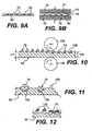
- FIG. 9 illustrates schematically a process of separating mask 50 and carrier 60 from each other.
- mask 50 retains preferably all, but at least the majority of the hard particles 80, and carrier 60 the hard particles 75. More specifically, as shown in Figure 9 , mask 50 can be removed from carrier 60 by separating it from the carrier and coiling it up in a roll. It is to be understood that the process of separation can be in a continuous or semi-continuous manner or in a discreet or batch manner.
- adhesive substance 90 should not make it difficult to separate them from each other.
- substance 90 in the most cases should be sufficiently tacky so that particles 75 will adhere to it, but not so strong that it makes it difficult to separate mask 50 from the carrier.
- the particles 75 left on the carrier are in contact with or are at least partially surrounded with a retaining matrix material.
- a retaining matrix material As shown in Figure 9A , this can be, for example, a powdered sinterable matrix material 76, which is then heated to melt or sinter the material and hold particles 75 in the desired pattern and form an abrasive material.
- the carrier can be a part of the abrasive material or it can be removed following sintering.
- a preform of sinterable matrix material can be applied to one or both sides of the structure in addition to or in lieu of the material 76 or other retention type material.
- Figure 9B illustrates the situation where a preform 77 and 78 of sinterable material is applied to both sides of the assembly of Figure 9A , after which plates 79 will exert pressure on the assembly and heat will be applied to sinter the abrasive material.
- Material 76 can be omitted, or it can be a powdered sinterable matrix material or a fusible material.
- material 76 is a fusible material, it will melt at or below the final temperature of sintering of the preforms and assist in adhering the particles to one another and the retaining matrix provided by the preforms.
- the carrier 60 could be a preform of sinterable material that by itself will form a retaining matrix to hold the particles 75 during the above-described process of making the abrasive material.
- Further processing of carrier 60 and hard particles 75 after removal of the mask and before heating includes urging the particles into the carrier with a pair of opposed compacting means, e.g., rolls 130, 140 as shown in Figure 10 , particularly if carrier 60 is a preform of sinterable matrix material.
- the compacting rolls urge the hard particles 75 into carrier 60, deforming it.
- the original thickness 111 of the carrier 60 may be changed under some conditions of compacting or deforming, the resulting thickness 120 being smaller than the original thickness 111.
- the width (not shown in the Figures) of carrier 60 also may change under such compaction.
- the hard particles 75 can be at least partially or completely embedded in carrier 60.
- Different applications of the final products may require different levels of protrusion.
- production of a single layer face grinding tool there should be a protrusion of the hard particles over the surface 150 of the carrier 60 as shown in Figure 11 .
- the hard particles 75 can rest comfortably in nests 155 and thereby be anchored in the carrier.
- Other applications require preferably complete protrusion of the hard particles 75 into carrier/perform 60.
- adhesive substance 90 if adhesive substance 90 is present in nests 155 as a result of urging/compaction, it can be removed, along with any present on the carrier, e.g., by a heat, burn-out, suction action, vacuum or dissolving procedure.
- Removing substance 90 if present, can be an important step in manufacturing in order to reduce organic material, water and generation of gases under heat, especially for providing a clean process environment and a good retention between hard particles 75 and any permanent retaining material. It is particularly important for sintering, braising, fusing, electro-depositing and thermal setting, all with or without utilization of negative (vacuum) and/or protective and/or reduction atmospheres.
- a supplemental retention material 125 can be applied to the hard particles 75 and optionally at least partially to the carrier.
- the reason for calling this material 125 "supplemental" is that the carrier 60 by itself may also be providing a retaining matrix for the hard particles, particularly if it is of a sinterable matrix material.
- the supplemental retention material after proper treatment, will assist in permanently bonding hard particles 75 to carrier 60.
- the "supplemental" material 125 can be the only one that provides integrity of the hard particles and the carrier 60.
- the "supplemental" material 125 can function as a truly braze material according to the definition of the function of the braze process: integrating parts together via a liquid and then solidifying of the braze material. Therefore in this case the braze melts under heat (with a load and/or pressure applied or not) and then solidifies (with a load and/or pressure applied or not) in the process of manufacturing the abrasive material.
- the braze material is combined with (mixed with or applied onto) a non-braze type sinterable material, the braze, which melts at the proper temperature, can infiltrate into the skeleton (capillary channels) of said non-braze type sinterable material.
- This supplemental retention material can be in the form of a powder, chips, fibers, paste, slurry, tape, sheet, chopped, or crushed pieces of a solid material, cold compacted powders, molten metallic, preferably atomized materials and electrolytical solutions. It can be of metallic (e.g., metallic and alloy powders and mixtures) or non-metallic materials (e.g., thermal plastics, resins, epoxies.)
- the retention material can be chosen from pre-sintered or fully sintered powder material, cast powder tape, roll compacted powder tape or plate, including cellular type material and metallic based mesh material.
- mask 50 is not removed from carrier 60 at the time the supplemental retention material is applied, it can also be used to assist in holding particles 80 to the mask to aid in their subsequent removal with the mask.
- hard particles 80 include any retention material, to allow their recovery for future use following their removal with the mark, the retention material should be able to be separated from them. Specifically, the hard particles should be cleaned of the retention material prior to returning them for further use. Nevertheless, in some cases the removed hard particles can be returned for reuse even with the presence of traces of the retention material.
- Compaction of carrier 60 and the urging of hard particles 75 into the carrier as shown in Figures 9B and 10 can be performed before removing mask 50 as shown in Figure 13 .
- mask 50 is thin, or deformable or elastic or resilient.
- compacting means such as plates 79 or rolls 130-1 and 140-1, mask 50 is compressed, hard particles 80 are urged at least partially into the mask and hard particles 75 are also urged into carrier 60. After mask 50 is removed, the resulting material is similar to that shown in Figure 11 .
- the compacting means can be flat, corrugated, rectangular, round, etc.
- the compacting means can be a part of or attached to an electrical, hydraulic, pneumatic, vibratory (including ultrasonic) machine.
- Figures 14-16 An embodiment when mask 50 is a thin substance relative to the linear dimensions of the hard particles 80 and 75 (e.g., 3.0 x 10 -1 to 1.0 x 10 -6 of a linear dimension of the hard particles) is illustrated in Figures 14-16.
- Figure 14 shows hard particles 80 positioned on an outer surface 150 of mask 50, and hard particles 75 on an outer surface 160 of carrier 60.
- Figure 15 shows the structure after the hard particles 80 and 75 are urged (by compacting means such as shown in Figures 10 and 13 ) into mask 50 and carrier 60 respectively.
- Figure 16 shows the structure of carrier 60 and the particles 75 embedded therein after separation of mask 50 and the particles 80 adhered to it from the carrier.
- Further treatment of the compressed carrier 60 containing hard particles 75 to provide permanent retention of the particles can comprise a variety of methods including, but not limited to, heating, sintering, braising, fusing, curing, and any combination of them, all with or without pressure and/or with or without vacuum; thermal spraying and electro-depositing; all performed in a continuous and/or semicontinuous and/or batch manner; and any combination of them. Many of these processes are disclosed in the above-referenced U.S. patents including U.S. Patent No. 5,203,880 .
- the level of protrusion of the hard particles 75 into and/or out of carrier 60 can vary from 0-100%.
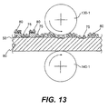
- Figure 16A shows an abrasive material made from a compacted carrier 60 containing hard particles 75, only one being shown, using an optional supplementary retention material 125, that has penetrated into the carrier 60.
- Figure 17 shows a mask 50 having a plurality of pockets or channels 165 on at least the side 170 of the mask that is to be against the surface 180 of carrier 60 carrying hard particles 75. Under some compression force (e.g., as show in Figure 13 ) and/or a vacuum, air is removed at least partially from these pockets 165 to seal the mask to surface 180. As a result, mask 50 sticks to surface 180 of the carrier.
- This design of the mask and method of application allows for easy separation of the mask from the carrier (e.g., as shown in Figure 9 ). Other methods (e.g., releasing vacuum) letting air penetrate into these pockets 165 may be employed.
- Pockets or channels 165 can be made by a variety of methods including but not limited to compression, molding, etching, and microreplication.
- the masks used in this invention can be made out of or utilize a variety of materials of different classes and origins including metallic, alloy, and non-metallic materials; organic materials, e.g., esters; silk; textiles; papers; foils, films, thin films, tapes, sheets and plates.
- the masks and/or adhesives used can be tacky materials and glues; pressure sensitive adhesives; one- and double sided adhesive materials (preferably in the form of tapes, sheets and plates); pressure sensitive adhesive tapes; plastics; resins; rubbers, pastes; glasses; ceramics, fiber glasses; gels; mesh type materials including wire mesh filters, woven and non-woven meshes, expanded, punched, cut, drilled and otherwise machined and/or deformed materials; powder and/or fiber materials, including cast, compacted and at least partially sintered materials; and any combinations of these with or without other materials.
- the mask preferably should be deformable and/or elastic and/or resilient.
- the thickness of the mask is not limited, but preferably should be comparable with the linear dimensions of the hard particles or substantially smaller (i.e., 2.0 to 10 x 10 -6 of a linear dimension/size of the hard particles).
- Processes for making the masks include laser discharge, punching or cutting as well as electrochemical etching processes. Many processes, including laser punching, can provide masks of substantial sizes (e.g., 24 inches wide, 100 ft. long) or masks in the form of the wound roll, a hole cylinder (so called drum), or continuous belts with or without seams.
- a pressure sensitive adhesive sheet or tape one- or double sided can be converted into a mask by a laser punching tool, that cuts or punches through openings in the tape.
- the mask may have different adhesive properties on different sides of the mask.
- the side of the mask adjacent to the carrier may have a low tacky ability relative to the surface of the carrier to facilitate easy separation of the mask from the carrier, while the side of the mask receiving the hard particles has a relatively strong adhesion to the hard particles to facilitate good adhesion of the hard particles to the mask and therefore minimize the falling of hard particles onto the carrier during separation of the mask and the carrier from each other.
- the carrier can be made out of many materials, including but not limited to, metallic, alloy, and non-metallic materials; organic materials; silk; textiles; paper, foils, tapes, plates, plastics, resins; rubber; pastes; glasses, ceramics, fiber glasses; mesh type materials including wire mesh, filters, woven and non-woven meshes, expanded, punched, cut, drilled and otherwise machined and/or deformed materials; powder and/or fiber materials, including but not limited to, preforms, including, but not limited to, green compacts, roll compacted materials, cast powders and/or fibers, sintered and/or partially sintered and/or infiltrated materials; and any combinations of them with or without other materials.
- the carrier can be a flexible, rigid, single layer or a composite, multi-layered one; can comprise one or several materials; can be a solid material or powder material before or after compaction and/or thermal processing, can comprise pores, including open pores and capillary channels.
- the carrier can be flexible, rigid, of non-porous or porous material, cast and rolled material; alloys, composite, powder non-sintered, pre-sintered and fully sintered material.
- a preform of sinterable matrix material e.g., a cast powder preform is used as carrier 60.
- This preform is disclosed in U.S. Patent No. 5,620,489 . It can be utilized as cast and/or cured and/or pre-sintered and/or fully sintered.
- This cast material in any of the above mentioned stages, as the carrier receives the hard particles that pass through the openings in the mask and allows them to be affixed to the carrier, for example, by urging the hard particles into it. This allows one to minimize the amount or not to use any adhesive materials at all for affixing the hard particles to the carrier 60. Such minimization or absence of the adhesive material contributes to the productivity and the quality of the final products.
- Figures 3-17 show carrier 60 as a solid material, e.g., a plate, foil or tape
- Figure 18 shows that the carrier 60-2 can be of a mesh or cellular type material.
- Figure 18 is similar to Figure 4 with respect to the stage in the process for making the abrasive material and shows a plurality of hard particles 70-2, a plurality 75-2 of hard particles within the openings 190 of the cellular carrier and a plurality 80-2 of hard particles on the mask 50-2.
- Figure 18 also shows that the cellular carrier 60-2 is sealed from the side opposite mask 50-2 by a further material or carrier 200, that prevents hard particles from falling through the openings 190 that are not covered by the mask.
- Figure 19 is a modification of Figure 18 , and shows that a single layer of the hard particles 75-3 or one hard particle per cell can be formed within cellular carrier 60-3.
- cellular carrier 60-3 could also play a role as a distributing mask and in this case carrier 200-3 would be a secondary carrier.
- Carrier 60-3 being a mask could also be removed from secondary carrier 200-3 leaving secondary carrier 200-3 with hard particles 75-3 on its surface according to the combined effect of mask 50-3 and carrier-mask 60-3.
- Secondary carrier 200-3 can be made out of the same materials and by the same ways as any carrier material 60. Further, the secondary carrier 200-3 and/or hard particles 75-3 can be processed the same ways as described above.
- Figure 19A shows secondary carrier 200-3 of Figure 19 after removal of mask 50-3 and mask-carrier 60-3, and prior to surrounding the hard particles with a retention matrix material.
- the mask is a combination of a wire mesh and a double sided pressure sensitive adhesive tape with openings therein on one side.
- the particles will form a pattern on the carrier corresponding to the openings in the tape and the particles in each opening, a pattern corresponding to the wire mesh.
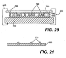
- Figure 20 illustrates a conventional holding means that can be used to keep a carrier and a mask tightly together in the process of filling and removing the hard particles.
- the figure shows a carrier 650, a cellular carrier-mask 680, a distributing mask 700, and hard particles 720 in the openings of the cellular carrier mask and opposing loading elements 760 and 740.
- the load providing and controlling the pressure against elements 650, 680, and 700 and keeping them together, can be generated by the weight of the loading elements or by an additional weight load or mechanical force 800, e.g., application of pressure against the elements of a C-clamp, a magnetic field, etc.
- the terms "sinter,” sintering.” “sintering under pressure or hot compacting,” “sintering in a solid state,” “sintering in a liquid state,” “liquid sintering,” “partial sintering,” “sintering with infiltration,” “brazing,” “fusing,” “depositing,” “thermal setting,” “thermal spraying,” “electro-depositing,” “electroplating,” and their synonyms and substitutes mean the same; namely consolidation of the components into a useful abrasive material and/or tool, and providing permanent retention of the hard particles (for the life of the hard particles in the abrasive article) on or without the carrier or the abrasive tool.
- the carrier is a metallic foil or plate or a fully sintered material or solid metal tool carrier (i.e., a steel) when adequate heat and/or pressure and/or atmosphere is applied to both the carrier and the retention material, this material is sintered or melts and plays the role of a brazing or fusing material, permanently affixing or attaching the hard particles in or to the carrier.
- the carrier is a powder composition and/or preform of a base retention material (e.g., a non-sintered or partially sintered Co-Ni-Fe powder composition optionally comprising a Ni-Cr-P additive,)
- a supplemental retention material such as 125 in Figure 12
- this supplemental retention material melts and infiltrates into the carrier.
- the process is called "sintering under pressure" with or without liquid phase.
- the generation of the liquid phase depends upon the composition and combination of the carrier (which can be a retention material by itself) and the retention material and their components.
- the retention or retaining matrix material should be a sinterable matrix material that is sintered in a mold under pressure with our without a protective and/or a negative pressure atmosphere. In addition, it should take place in a furnace with a protective and/or negative pressure atmosphere; and with a liquid phase generated by components of the carrier and/or a supplemental retention material if present.
- a soft, easy deformable powder preform of a sinterable matrix material as described in U.S. Patent No. 5,620,489 is used as the carrier and a supplemental retention material in the form of a powder (by dusting onto at least the hard particles and/or the carrier) is used to assist in securing the hard particles in the desired pattern.
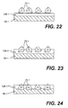
- Figure 22 shows a modification of Figure 12 .
- the supplemental retention material 125 of Figure 12 is shown here as a preform 125-1 that is placed against the carrier 60-1.
- the hard particles 75-1 are distributed on preform 125-1 in the desired pattern in the same manner as described above.
- Figure 23 shows these particles 75-1 urged at least partially into the material 125-1 or, as shown in Figure 24 also into the carrier 60-1 through the material 125-1.
- Figure 25 shows a modification of Figures 22-24 .
- the material 125-1 of Figure 22 is a preform 125-2 placed on top of the particles 75-2 which are distributed on carrier 60-1 in the desired pattern and in the same manner as described above.
- Figure 26 shows these particles 75-2 urged at least partially into material 125-2 and the carrier.
- the hard particles can protrude from a surface of the preform 125-2 and the carrier.
- Means for providing protrusion of the hard particles over the retention surface are described in the U.S. Patent No. 5,203,880 . These means, which include soft penetrable separators, can be utilized before or during heating to form the composite material.
- the carrier for the particles can be a solid material that is used only to support the particles during processing and later discarded.
- the particles after being distributed on the carrier in the desired pattern in the same manner as described above, are surrounded with a retention material such as a sinterable matrix material which is then sintered to form an abrasive article with the particles embedded in and firmly held in place by the sintered material.
- the material can be provided by applying sinterable matrix powder over the particles or by providing a preform of sinterable matrix material over and/or under the particles and then urging the particles on the preform either before and or during sintering.
- the material of the carrier 60 itself can be of a retention material (i.e., cobalt, nickel, iron, manganese, molybdenum, tungsten, nickel - bronze compositions) that will integrate and bond with the hard particles. Sintering in a solid state, sintering under load or pressure in a furnace or mold of a sinter press are the best processes for such materials.
- a retention material i.e., cobalt, nickel, iron, manganese, molybdenum, tungsten, nickel - bronze compositions
- the carrier also include a supplementary, retention-reinforcing material (i.e., 0.5 - 10, but preferably 3-7 weight percent).
- retention-reinforcement materials are low temperature braze filler materials, i.e., silver, copper, zinc and/or tin based materials and high temperature braze filler, fusing and hard facing materials.
- These retention-reinforcing materials preferably comprise at least some carbide forming metals of IVA, VA, VIA, VIIIA IIIB and IVB groups of the Periodic Table Of The Elements (i.e., chromium, titanium) and/or some metals of IB and IIB groups of the Table.
- the material of the carrier is that it consist predominantly of supplementary, retention-reinforcing materials (more than 50 weight %) with optional additives as described above. Sintering in a liquid phase, sintering with infiltration or in some cases direct brazing and fusing are the best options for such combinations of materials.
- a further option for the carrier 60 is that it consist of a material of any of the above and in addition is provided with a further supplementary retention material as shown in Figure 12 .
- the supplementary retention material can comprise at least some carbide forming metals of IVA, VA, VIA, VIIA IIB and IVB groups of the Periodic Table Of The Elements (i.e., chromium, titanium) and/or some metals of IB and IIB groups of the Table.
- abrasive articles comprising hard particles retained by a retaining matrix, preferably in a non-random manner, and preferably retained by predominantly metallic components, it is not important which specific process (sintering, infiltration, etc.) is used to permanently retain the hard particles.
- the above disclosed single layered materials can also be in multiple layer form by assembling various single layers together and consolidating them into a unitary assembly with and/or without adding supplementary parts to the assembly.
- processing include thermal setting, vulcanization, sintering, braising (all in a mold, furnace; by induction, conventional, resistant heating; by flame/torch, adhesive, epoxy, glue, etc.).
- Additional structural elements such as supports, interlays, tool working surfaces and tool carriers can be added or assembled with the composite material or its assembly and used as the carrier. This assembly can be made prior to and/or after final processing of the composite material, e.g., prior to or after sintering.
- the hard particles can be chosen from any kind and type of natural and synthetic materials providing an abrasive quality, e.g., diamonds (natural, synthetic and polycrystalline); nitrides (e.g., cubic boron nitride) carbides, borides, or any mineral abrasives preferably of highest hardness or any combination thereof.
- abrasive quality e.g., diamonds (natural, synthetic and polycrystalline); nitrides (e.g., cubic boron nitride) carbides, borides, or any mineral abrasives preferably of highest hardness or any combination thereof.
- Articles made according to this method include abrasive and superabrasive single and multiple layer surfaces, tools and wear resistant articles and parts, tools for cutting, grinding, roughening, drilling, dressing, polishing, lapping.
- these articles include, but are not limited to, face and rotary grinding discs, drums and dressers; segments; replaceable/disposable abrasive segments and parts for the abrasive tools and wear resistant articles; circular and reciprocating segmented and continuous rim blades, drill bits; beads for wire saws.
- the useful abrasive parts for the abrasive and wear resistant articles and parts can be obtained by extracting (i.e. by water jet and/or laser) the useful abrasive parts from the unitary structure as disclosed in the U.S. Patent No. 5,791,330 and co-pending U.S. patent application No. 09/448,840 entitled "Method for Making a Sintered Article and Products Produced Thereby.”
- the extracted parts can then be integrated together, for example, by brazing, welding, or sintering and used as a single unit.
- the carrier is a solid material like a steel foil or plate or pre-sintered or fully sintered and the particles are at least partially urged (indented, embedded) into this carrier for temporary retention
- permanent retention of the particles in the carrier can be provided by supplying material in the form of brazing or fusing powder or preform (optionally and preferably with a flux) prior to or after positioning or urging the particles into the carrier. A heat process will then melt the material and braze it thereby securing the particles to the carrier.
- the carrier is a solid material or a fully sintered substance (i.e., with a predominately closed residual porosity of 0-5%) and there is no penetration of the particles into it, the molten material braze will fuse the hard particles to the carrier. In this case there is no substantial physical penetration of the molten material into the carrier.
- the carrier 60 as a solid or properly pre-sintered substance will not shrink in the process of heating.
- a furnace including a sinter or special braising furnace (preferably with vacuum), induction fixture, open flame/torch can be used to provide the necessary heat for this process.
- nickel or cobalt based fusing and braising filler metallic powders and preforms preferably comprising carbide forming elements such as chromium, titanium, boron, silica.
- Compositions (in weight percents) "4-25%Cr, 0-10%P, 2-3%B, 0-10% Si, 0-4% Fe, 0-15% W, 0-37% Mn, 0-5% Cu, 0-5 Ta, 0-4% Al, 0-.02%Y, 0-.05% La, 0-0.03%Re, Ni and/or Co - balance" are readily available in the form of powders and/or pastes and/or preforms (tapes) from Sulzer Plasma Tecknik, Inc.
- the same materials set forth above and/or their components can be used as the carrier in a form of powder or un-sintered or partially sintered powder preform, all comprising substantial open porosity (i.e., 90 to 30%).
- the same materials as shown also can be used as a supplemental retention material in the form of a powder, paste or preform. In this case since the powder or preformed carrier has substantial open porosity it will shrink in the process of heating.
- the application of heat should preferably be accompanied with weight loading or pressure against the assembly of the carrier and the hard particles.
- This process can be performed in a furnace or in so-called sinter press and is usually referred to as hot compacting or sintering under pressure.
Landscapes
- Engineering & Computer Science (AREA)
- Mechanical Engineering (AREA)
- Polishing Bodies And Polishing Tools (AREA)
- Laminated Bodies (AREA)
Claims (32)
- Verfahren zur Herstellung eines Abrasivmaterials umfassend mehrere harte abrasive Partikel, die in einer Haltematrix verteilt sind, um die Partikel ortsfest zu halten, wobei das Verfahren die folgenden Schritte umfasst:- Anordnen einer Maske (10, 30, 50) mit darin befindlichen Öffnungen (15-24, 35, 40, 55) gegen einen Träger (60) zum Lagern mehrerer der Partikel,- Zuführen mehrerer harter Partikel (70) an eine vom Träger (60) entfernte Außenseite der Maske (10, 30, 50), so dass ein Teil (75) der mehreren harten Partikel (70) durch die Öffnungen (15-24, 35, 40, 55) der Maske (10, 30, 50) hindurchtritt und auf dem Träger (60) ein Muster aus harten Partikeln (75) bildet, das den Öffnungen (15-24, 35, 40, 55) der Maske (10, 30, 50) entspricht, und ein weiterer Teil (80) der mehreren harten Partikel (70) auf der Maske (10, 30, 50) angeordnet ist,- Trennen der Maske (10, 30, 50) vom Träger (60), wobei das Muster aus harten Partikeln (75) auf dem Träger (60) verbleibt,- wenigstens teilweises Umgeben der harten Partikel (75) auf dem Träger (60) mit einem sinterbaren Matrix-Material (76), und- Erhitzen des sinterbaren Matrix-Materials (76), um das Material dazu zu veranlassen, eine Haltematrix zu bilden, die die harten Partikel (75) in dem Muster hält, wodurch das abrasive Material gebildet wird,dadurch gekennzeichnet, dass
die Maske (10, 30, 50) auf der Außenseite der Maske (10, 30, 50), an der die harten abrasiven Partikel anhaften, mit Befestigungsmitteln (100) versehen ist, so dass, wenn die harten Partikel (70) der Maske zugeführt werden, der Anteil (80) von diesen auf der Maske (10, 30, 50) an der Maske (10, 30, 50) anhaftet und die an der Maske (10, 30, 50) angehafteten harten Partikel (80) mit der Maske (10, 30, 50) entfernt werden, wenn die Maske (10, 30, 50) vom Träger (60) getrennt wird. - Verfahren nach Anspruch 1,
wobei es sich bei dem Träger (60) um eine Vorform (77, 78) aus sinterbarem Matrix-Material handelt. - Verfahren nach Anspruch 2,
wobei die Partikel (75) wenigstens teilweise von dem sinterbaren Matrix-Material umgeben werden, indem die Partikel (75) zumindest teilweise in die Vorform (77, 78) eingedrückt werden. - Verfahren nach Anspruch 3,
wobei die Partikel (75) während des Erhitzens des Materials in die Vorform (77, 78) eingedrückt werden. - Verfahren nach Anspruch 3,
wobei die Partikel (75) vor dem Erhitzen des Materials in die Vorform (77, 78) eingedrückt werden. - Verfahren nach Anspruch 3, 4 oder 5,
wobei die Vorform (77, 78) aus sinterbarem Matrix-Material in ihr verteilte harte Partikel aufweist. - Verfahren nach Anspruch 1,
wobei die Partikel (75) zumindest teilweise von dem sinterbaren Matrix-Material (76) umgeben werden, indem das sinterbare Matrix-Material (76) den Partikeln (75) und dem Träger (60) nach dem Trennen der Maske (10, 30, 50) von dem Träger (60) zugeführt wird. - Verfahren nach Anspruch 1,
wobei der Träger (60) eine haftende Beschichtung (90) aufweist, an der die Partikel (75), die die Öffnungen (15-24, 35, 40, 55) in der Maske (10, 30, 50) durchtreten, anhaften. - Verfahren nach Anspruch 1,
wobei der Träger (60) einen Teil des abrasiven Materials bildet. - Verfahren nach Anspruch 1,
wobei der Träger (60) ein Maschenmaterial (60-2) ist. - Verfahren nach Anspruch 10,
wobei das Maschenmaterial (60-2) einen Teil des abrasiven Materials bildet. - Verfahren nach Anspruch 1,
wobei der Träger (60) nach dem Erhitzen des sinterbaren Matrix-Materials (76) von dem abrasiven Material entfernt wird. - Verfahren nach Anspruch 1,
wobei auch die dem Träger (60) benachbarte Seite der Maske (10, 30, 50) mit Befestigungsmitteln versehen ist, um die Maske (10, 30, 50) temporär an dem Träger (60) zu befestigen, während die Partikel (70) dieser zugeführt werden, wobei das haftende Material mit der Maske (10, 30, 50) entfernt wird, wenn die Maske (10, 30, 50) vom Träger (60) getrennt wird. - Verfahren nach Anspruch 13,
wobei es sich bei den Befestigungsmitteln der Maske (10, 30, 50) um eine Beschichtung mit einem Adhäsivmaterial handelt. - Verfahren nach Anspruch 1,
weiterhin umfassend das Eindrücken der Partikel (75) durch die Öffnungen (15-24, 35, 40, 55) in der Maske (10, 30, 50) in den Träger (60), bevor die Maske (10, 30, 50) von dem Träger (60) getrennt wird. - Verfahren nach Anspruch 1,
weiterhin umfassend das Eindrücken der Partikel (75) in den Träger (60), nachdem die Maske (10, 30, 50) entfernt wurde und bevor diese zumindest teilweise von dem sinterbaren Matrixmaterial (76) umgeben werden. - Verfahren nach Anspruch 8,
wobei die nicht an der Maske (10, 30, 50) oder dem Träger (60) anhaftenden Partikel entfernt werden, bevor die Maske (10, 30, 50) von dem Träger (60) getrennt wird. - Verfahren nach Anspruch 1,
wobei die Maske (10, 30, 50) mehrere Öffnungen (15-24, 35, 40, 55) derselben Form aufweist. - Verfahren nach Anspruch 1,
wobei die Befestigungsmittel (100) eine Schicht aus Adhäsivmaterial auf der Außenseite der Maske umfassen. - Verfahren nach Anspruch 1,
wobei es sich bei der Maske (10, 30, 50) um ein drucksensitives Adhäsivband handelt, wobei das Adhäsivmaterial auf dem Band die Befestigungsmittel (100) bildet. - Verfahren nach Anspruch 1,
wobei es sich bei der Maske (10, 30, 50) um ein doppelseitiges Adhäsivband handelt, wobei das Adhäsivmaterial auf der einen Seite die Befestigungsmittel (100) bildet und das Adhäsivmaterial auf der anderen Seite zum temporären Befestigen der Maske (10, 30, 50) an dem Träger (60) dient, während die Partikel (70) dieser zugeführt werden. - Verfahren nach Anspruch 1,
wobei die Maske (10, 30, 50) durch ein Aufwickeln zu einer Rolle von dem Träger (60) getrennt wird. - Verfahren nach Anspruch 1,
weiterhin umfassend das Eindrücken der Partikel (75) in den Träger (60) vor dem Erhitzen des sinterbaren Matrix-Materials (76). - Verfahren nach Anspruch 23,
wobei die Partikel (75) in den Träger (60) eingedrückt werden, nachdem die Maske (10, 30, 50) entfernt wurde. - Verfahren nach Anspruch 23,
wobei die Partikel (75) in den Träger (60) eingedrückt werden, bevor die Maske (10, 30, 50) entfernt wird. - Verfahren nach Anspruch 1,
weiterhin umfassend das Zuführen eines zusätzlichen Haltematerials (125) zu den auf dem Träger (60) befindlichen Partikeln (75), bevor das sinterbare Matrix-Material (76) erhitzt wird. - Verfahren nach Anspruch 26,
wobei das zusätzliche Haltematerial (125) ein schmelzbares Material ist, dessen Schmelztemperatur niedriger als die des sinterbaren Matrix-Materials (76) ist. - Verfahren nach Anspruch 26,
wobei es sich bei dem zusätzlichen Haltematerial (125) um ein Lötmaterial handelt. - Verfahren nach Anspruch 1,
wobei es sich bei dem sinterbaren Matrix-Material (76) um ein Lötmaterial handelt. - Verfahren nach Anspruch 1,
wobei das sinterbare Matrix-Material (76) ein Lötmaterial enthält. - Verfahren nach Anspruch 1,
wobei während des Erhitzens des sinterbaren Matrix-Materials (76) Druck auf den Träger (60) und die Partikel (75) ausgeübt wird. - Verfahren zur Herstellung eines Abrasivmaterials umfassend mehrere harte, abrasive Partikel, die in einer Haltematrix verteilt sind, um die Partikel ortsfest zu erhalten, wobei das Verfahren die folgenden Schritte umfasst:- Anordnen einer Maske (10, 30, 50) mit darin befindlichen Öffnungen (15-24, 35, 40, 55) gegen einen Träger (60) zum Lagern mehrerer der Partikel,- Zuführen mehrerer harter Partikel (70) an einer vom Träger (60) entfernten Außenseite der Maske (10, 30, 50), so dass ein Teil (75) der mehreren harten Partikel (70) durch die Öffnungen (15-24, 35, 40, 55) der Maske (10, 30, 50) hindurchtritt und auf dem Träger (60) ein Muster aus harten Partikeln (75) ausbildet, das den Öffnungen (15-24, 35, 40, 55) der Maske (10, 30, 50) entspricht, und ein weiterer Teil (80) der mehreren harten Partikel (70) auf der Maske (10, 30, 50) angeordnet ist,- Trennen der Maske (10, 30, 50) vom Träger (60), wobei das Muster aus harten Partikeln (75) auf dem Träger (60) verbleibt,- wenigstens teilweises Umgeben der harten Partikel (75) auf dem Träger (60) mit einem sinterbaren Matrix-Material (76), und- Erhitzen des sinterbaren Matrix-Materials (76), um das Material dazu zu veranlassen, eine Haltematrix zu bilden, die die harten Partikel (75) in dem Muster hält, wodurch das abrasive Material gebildet wird,dadurch gekennzeichnet, dass
nach dem Schritt des Zuführens mehrerer harter Partikel (70) an eine vom Träger (60) entfernte Außenseite der Maske (10, 30, 50), die auf der äußeren Oberfläche der Maske (10, 30, 50) verbleibenden harten Partikel (80) an der Maske (10, 30, 50) befestigt werden, so dass die harten Partikel (80) mit der Maske (10, 30, 50) entfernt werden, wenn die Maske (10, 30, 50), die die an ihr anhaftenden harten Partikel (30) enthält, von dem Träger (60) getrennt wird.
Applications Claiming Priority (3)
| Application Number | Priority Date | Filing Date | Title |
|---|---|---|---|
| US17215199P | 1999-12-17 | 1999-12-17 | |
| US172151P | 1999-12-17 | ||
| PCT/US2000/034245 WO2001043918A2 (en) | 1999-12-17 | 2000-12-18 | Abrasive surface and article and methods for making them |
Publications (2)
| Publication Number | Publication Date |
|---|---|
| EP1237679A2 EP1237679A2 (de) | 2002-09-11 |
| EP1237679B1 true EP1237679B1 (de) | 2009-04-01 |
Family
ID=22626579
Family Applications (1)
| Application Number | Title | Priority Date | Filing Date |
|---|---|---|---|
| EP00986502A Expired - Lifetime EP1237679B1 (de) | 1999-12-17 | 2000-12-18 | Schleifoberfläche und -artikel und deren hestellungsverfahren |
Country Status (10)
| Country | Link |
|---|---|
| EP (1) | EP1237679B1 (de) |
| JP (1) | JP4426148B2 (de) |
| KR (1) | KR100537474B1 (de) |
| CN (1) | CN1188253C (de) |
| AU (1) | AU2273001A (de) |
| BR (1) | BR0016466B1 (de) |
| DE (1) | DE60041926D1 (de) |
| HK (1) | HK1051340A1 (de) |
| TW (1) | TW467809B (de) |
| WO (1) | WO2001043918A2 (de) |
Families Citing this family (19)
| Publication number | Priority date | Publication date | Assignee | Title |
|---|---|---|---|---|
| KR100754282B1 (ko) * | 2006-02-08 | 2007-09-03 | 엠.씨.케이 (주) | 다공성 연마지 및 그 제조방법 |
| WO2008027714A1 (en) * | 2006-08-30 | 2008-03-06 | 3M Innovative Properties Company | Extended life abrasive article and method |
| CN101376234B (zh) * | 2007-08-28 | 2013-05-29 | 侯家祥 | 一种研磨工具磨料颗粒有序排列的方法 |
| RU2569254C2 (ru) | 2009-08-14 | 2015-11-20 | Сэнт-Гобэн Эбрейзивс, Инк. | Абразивное изделие |
| EP2651651B1 (de) * | 2010-12-17 | 2019-01-23 | 3M Innovative Properties Company | Übertragungsmaterial mit partikeln von unterschiedlicher grösse und verfahren dafür |
| CN102242336B (zh) * | 2011-06-24 | 2013-02-13 | 清华大学 | 一种降低硬质薄膜应力的薄膜制备方法 |
| TW201402274A (zh) | 2012-06-29 | 2014-01-16 | 聖高拜磨料有限公司 | 研磨物品及形成方法 |
| TW201404527A (zh) | 2012-06-29 | 2014-02-01 | 聖高拜磨料有限公司 | 研磨物品及形成方法 |
| FR3014718A1 (fr) * | 2013-12-18 | 2015-06-19 | Saint Gobain Diamantwerkzeuge Gmbh & Co Kg | Procede de fabrication d'un superabrasif et produit obtenu |
| TWI664057B (zh) | 2015-06-29 | 2019-07-01 | 美商聖高拜磨料有限公司 | 研磨物品及形成方法 |
| CN107848094B (zh) * | 2015-07-08 | 2020-09-11 | 3M创新有限公司 | 用于制造磨料制品的系统和方法 |
| JP6900523B2 (ja) * | 2015-09-07 | 2021-07-07 | 日鉄ケミカル&マテリアル株式会社 | 研磨布用ドレッサー |
| KR101698989B1 (ko) * | 2016-01-22 | 2017-01-24 | 주식회사 썬텍인더스트리 | 요철을 갖는 연마물품 및 이의 제조방법 |
| CA3117099A1 (en) * | 2018-11-16 | 2020-06-18 | Magna Imperio Systems Corp. | Spacers for ion-exchange device |
| US11478752B2 (en) | 2019-04-09 | 2022-10-25 | Magna Imperio Systems Corp. | Electrodialysis systems with decreased concentration gradients at high recovery rates |
| DE102019205745A1 (de) | 2019-04-18 | 2020-10-22 | Ecocoat Gmbh | Beschichtetes abrasives Werkzeug und Verfahren zum Herstellen desselben |
| MX2021015644A (es) | 2019-06-25 | 2022-02-03 | Magna Imperio Systems Corp | Proceso de electrodialisis y dispositivos de electrodialisis de membrana bipolar de remocion de silice. |
| DE102019217388A1 (de) * | 2019-11-11 | 2021-05-12 | Aktiebolaget Skf | Reibungsfolie |
| CN114248209B (zh) * | 2021-12-24 | 2023-01-03 | 江苏韦尔博新材料科技有限公司 | 一种金刚石-焊料复合带及基于其的钎焊金刚石工具的制备工艺 |
Family Cites Families (6)
| Publication number | Priority date | Publication date | Assignee | Title |
|---|---|---|---|---|
| US2876086A (en) * | 1954-06-21 | 1959-03-03 | Minnesota Mining & Mfg | Abrasive structures and method of making |
| JP2593829B2 (ja) * | 1990-08-17 | 1997-03-26 | 鐘紡株式会社 | 合成砥石 |
| US5380390B1 (en) * | 1991-06-10 | 1996-10-01 | Ultimate Abras Systems Inc | Patterned abrasive material and method |
| JPH0569334A (ja) * | 1991-09-12 | 1993-03-23 | Brother Ind Ltd | メタルボンド砥石の製造方法 |
| US6537140B1 (en) * | 1997-05-14 | 2003-03-25 | Saint-Gobain Abrasives Technology Company | Patterned abrasive tools |
| US5832360A (en) * | 1997-08-28 | 1998-11-03 | Norton Company | Bond for abrasive tool |
-
2000
- 2000-12-16 TW TW089127028A patent/TW467809B/zh not_active IP Right Cessation
- 2000-12-18 CN CNB00817301XA patent/CN1188253C/zh not_active Expired - Fee Related
- 2000-12-18 BR BRPI0016466-6A patent/BR0016466B1/pt not_active IP Right Cessation
- 2000-12-18 JP JP2001545037A patent/JP4426148B2/ja not_active Expired - Fee Related
- 2000-12-18 HK HK03101768.5A patent/HK1051340A1/zh unknown
- 2000-12-18 KR KR10-2002-7007638A patent/KR100537474B1/ko not_active Expired - Fee Related
- 2000-12-18 WO PCT/US2000/034245 patent/WO2001043918A2/en not_active Ceased
- 2000-12-18 AU AU22730/01A patent/AU2273001A/en not_active Abandoned
- 2000-12-18 DE DE60041926T patent/DE60041926D1/de not_active Expired - Lifetime
- 2000-12-18 EP EP00986502A patent/EP1237679B1/de not_active Expired - Lifetime
Also Published As
| Publication number | Publication date |
|---|---|
| CN1420810A (zh) | 2003-05-28 |
| WO2001043918A2 (en) | 2001-06-21 |
| JP2003516871A (ja) | 2003-05-20 |
| TW467809B (en) | 2001-12-11 |
| KR20030028449A (ko) | 2003-04-08 |
| AU2273001A (en) | 2001-06-25 |
| WO2001043918A3 (en) | 2002-03-28 |
| KR100537474B1 (ko) | 2005-12-19 |
| EP1237679A2 (de) | 2002-09-11 |
| WO2001043918A9 (en) | 2002-05-16 |
| HK1051340A1 (zh) | 2003-08-01 |
| BR0016466A (pt) | 2003-04-01 |
| DE60041926D1 (de) | 2009-05-14 |
| JP4426148B2 (ja) | 2010-03-03 |
| CN1188253C (zh) | 2005-02-09 |
| BR0016466B1 (pt) | 2009-08-11 |
Similar Documents
| Publication | Publication Date | Title |
|---|---|---|
| US6478831B2 (en) | Abrasive surface and article and methods for making them | |
| EP1237679B1 (de) | Schleifoberfläche und -artikel und deren hestellungsverfahren | |
| AU717867B2 (en) | Patterned abrasive tools | |
| EP0407568B1 (de) | Schleifwerkzeug und verfahren zur herstellung | |
| EP1430999B1 (de) | Verfahren zur Herstellung eines Abrasivmaterials | |
| KR100310788B1 (ko) | 분말예비성형체및그것으로제조된연마제품의제조방법. | |
| US5980678A (en) | Patterned abrasive material and method | |
| US6453899B1 (en) | Method for making a sintered article and products produced thereby | |
| AU760519B2 (en) | Method for making a sintered article and products produced thereby | |
| AU690560C (en) | Patterned abrasive material and method | |
| HK1069795B (en) | Method for making an abrasive material | |
| MXPA99010461A (en) | Patterned abrasive tools |
Legal Events
| Date | Code | Title | Description |
|---|---|---|---|
| PUAI | Public reference made under article 153(3) epc to a published international application that has entered the european phase |
Free format text: ORIGINAL CODE: 0009012 |
|
| 17P | Request for examination filed |
Effective date: 20020614 |
|
| AK | Designated contracting states |
Kind code of ref document: A2 Designated state(s): AT BE CH CY DE DK ES FI FR GB GR IE IT LI LU MC NL PT SE TR |
|
| AX | Request for extension of the european patent |
Free format text: AL;LT;LV;MK;RO;SI |
|
| RBV | Designated contracting states (corrected) |
Designated state(s): AT BE CH DE FR GB LI |
|
| 17Q | First examination report despatched |
Effective date: 20080306 |
|
| GRAP | Despatch of communication of intention to grant a patent |
Free format text: ORIGINAL CODE: EPIDOSNIGR1 |
|
| GRAS | Grant fee paid |
Free format text: ORIGINAL CODE: EPIDOSNIGR3 |
|
| GRAA | (expected) grant |
Free format text: ORIGINAL CODE: 0009210 |
|
| AK | Designated contracting states |
Kind code of ref document: B1 Designated state(s): DE FR GB |
|
| REG | Reference to a national code |
Ref country code: GB Ref legal event code: FG4D |
|
| REF | Corresponds to: |
Ref document number: 60041926 Country of ref document: DE Date of ref document: 20090514 Kind code of ref document: P |
|
| PLBE | No opposition filed within time limit |
Free format text: ORIGINAL CODE: 0009261 |
|
| STAA | Information on the status of an ep patent application or granted ep patent |
Free format text: STATUS: NO OPPOSITION FILED WITHIN TIME LIMIT |
|
| 26N | No opposition filed |
Effective date: 20100105 |
|
| REG | Reference to a national code |
Ref country code: HK Ref legal event code: WD Ref document number: 1051340 Country of ref document: HK |
|
| GBPC | Gb: european patent ceased through non-payment of renewal fee |
Effective date: 20091218 |
|
| PG25 | Lapsed in a contracting state [announced via postgrant information from national office to epo] |
Ref country code: GB Free format text: LAPSE BECAUSE OF NON-PAYMENT OF DUE FEES Effective date: 20091218 |
|
| PGFP | Annual fee paid to national office [announced via postgrant information from national office to epo] |
Ref country code: FR Payment date: 20141217 Year of fee payment: 15 |
|
| PGFP | Annual fee paid to national office [announced via postgrant information from national office to epo] |
Ref country code: DE Payment date: 20141230 Year of fee payment: 15 |
|
| REG | Reference to a national code |
Ref country code: DE Ref legal event code: R119 Ref document number: 60041926 Country of ref document: DE |
|
| REG | Reference to a national code |
Ref country code: FR Ref legal event code: ST Effective date: 20160831 |
|
| PG25 | Lapsed in a contracting state [announced via postgrant information from national office to epo] |
Ref country code: DE Free format text: LAPSE BECAUSE OF NON-PAYMENT OF DUE FEES Effective date: 20160701 |
|
| PG25 | Lapsed in a contracting state [announced via postgrant information from national office to epo] |
Ref country code: FR Free format text: LAPSE BECAUSE OF NON-PAYMENT OF DUE FEES Effective date: 20151231 |