EP1237674B1 - Bandsägeblatt mit verringerter rausch- und gleichmässiger zahnbelastungscharakteristik - Google Patents
Bandsägeblatt mit verringerter rausch- und gleichmässiger zahnbelastungscharakteristik Download PDFInfo
- Publication number
- EP1237674B1 EP1237674B1 EP00991945A EP00991945A EP1237674B1 EP 1237674 B1 EP1237674 B1 EP 1237674B1 EP 00991945 A EP00991945 A EP 00991945A EP 00991945 A EP00991945 A EP 00991945A EP 1237674 B1 EP1237674 B1 EP 1237674B1
- Authority
- EP
- European Patent Office
- Prior art keywords
- tooth
- pattern
- teeth
- pitch
- saw blade
- Prior art date
- Legal status (The legal status is an assumption and is not a legal conclusion. Google has not performed a legal analysis and makes no representation as to the accuracy of the status listed.)
- Expired - Lifetime
Links
Images
Classifications
-
- B—PERFORMING OPERATIONS; TRANSPORTING
- B27—WORKING OR PRESERVING WOOD OR SIMILAR MATERIAL; NAILING OR STAPLING MACHINES IN GENERAL
- B27B—SAWS FOR WOOD OR SIMILAR MATERIAL; COMPONENTS OR ACCESSORIES THEREFOR
- B27B33/00—Sawing tools for saw mills, sawing machines, or sawing devices
- B27B33/02—Structural design of saw blades or saw teeth
-
- B—PERFORMING OPERATIONS; TRANSPORTING
- B23—MACHINE TOOLS; METAL-WORKING NOT OTHERWISE PROVIDED FOR
- B23D—PLANING; SLOTTING; SHEARING; BROACHING; SAWING; FILING; SCRAPING; LIKE OPERATIONS FOR WORKING METAL BY REMOVING MATERIAL, NOT OTHERWISE PROVIDED FOR
- B23D61/00—Tools for sawing machines or sawing devices; Clamping devices for these tools
- B23D61/12—Straight saw blades; Strap saw blades
- B23D61/121—Types of set; Variable teeth, e.g. variable in height or gullet depth; Varying pitch; Details of gullet
- B23D61/1216—Repeating pattern of groups having three or more teeth
-
- B—PERFORMING OPERATIONS; TRANSPORTING
- B23—MACHINE TOOLS; METAL-WORKING NOT OTHERWISE PROVIDED FOR
- B23D—PLANING; SLOTTING; SHEARING; BROACHING; SAWING; FILING; SCRAPING; LIKE OPERATIONS FOR WORKING METAL BY REMOVING MATERIAL, NOT OTHERWISE PROVIDED FOR
- B23D61/00—Tools for sawing machines or sawing devices; Clamping devices for these tools
- B23D61/12—Straight saw blades; Strap saw blades
- B23D61/121—Types of set; Variable teeth, e.g. variable in height or gullet depth; Varying pitch; Details of gullet
- B23D61/1212—Varying pitch
Definitions
- the present invention relates to a band saw blade according to the preambles of claims 1 and 15.
- Typical prior art band saw blades comprise recurrent or repetitive patterns of teeth, wherein each pattern is defined by one or more groups of teeth including an unset leading tooth followed by a plurality of alternately set trailing teeth.
- Each recurrent pattern of teeth is typically referred to as the "pitch” pattern, “repeat” pattern or “milling” pattern of the band saw blade, since each pattern may be formed by a respective milling tool.
- Each pitch pattern may, in turn, define respective "set patterns” indicative of the manner in which the teeth of the pitch pattern are set.
- Each set pattern is defined by an unset leading tooth and a plurality of alternately set trailing teeth. For example, an "eight" tooth pitch pattern may define "three/five" set patterns.
- the pitch pattern comprises eight teeth, consisting of a first set pattern of three teeth, and a second set pattern of five teeth (thus the designation "three/five" set pattern).
- the first set pattern of three teeth is defined by a first unset leading tooth and two alternately set trailing teeth
- the second set pattern of five teeth is defined by a first unset leading tooth and four alternately set trailing teeth.
- a ten tooth pitch pattern having a "three/seven" set pattern consists of a first set pattern of three teeth and a second set pattern of seven teeth, with each set pattern including an unset leading tooth followed by alternately set trailing teeth.
- Each unset leading tooth typically has a plane of symmetry defining the sawing plane of the blade, and which is parallel to the side surfaces at the base of the blade.
- the alternately set trailing teeth are typically either “right” set or “left” set, wherein each "right set” tooth is tilted or set a predetermined angle to the right side of the plane of symmetry of the unset leading tooth, and each "left set” tooth is tilted or set at a predetermined angle to the left side of alternately setting trailing teeth.
- an "eight" tooth pitch pattern may define "three/five" set patterns. In this case, the pitch pattern comprises eight teeth, consisting of a first set pattern of three teeth, and a second set pattern of five teeth (thus the designation "three/five" set pattern).
- the first set pattern of three teeth is defined by a first unset leading tooth and two alternately set trailing teeth
- the second set pattern of five teeth is defined by a first unset leading tooth and four alternately set trailing teeth
- a ten tooth pitch pattern having a "three/seven" set pattern consists of a first set pattern of three teeth and a second set pattern of seven teeth, with each set pattern including an unset leading tooth followed by alternately set trailing teeth.
- Each unset leading tooth typically has a plane of symmetry defining the sawing plane of the blade, and which is parallel to the side surfaces at the base of the blade.
- the alternately set trailing teeth are typically either "right” set or “left” set, wherein each "right set” tooth is tilted or set at predetermined angle to the right side of the plane of symmetry of the unset leading tooth, and each "left set” tooth is tilted or set at a predetermined angle to the left side of the plane of symmetry of the unset leading tooth.
- the first tooth in the cutting direction of the band saw blade of a particular set direction within each set pattern is referred to as the "primary” tooth
- the next tooth in the set pattern of the same or like set direction is referred to as the "secondary” tooth
- the next tooth in the set pattern of the same or like set direction is referred to as the "tertiary” tooth, and so on.
- Certain prior art band saw blades have relatively long pitch patterns of, for example, eight or more teeth.
- one prior art band saw blade manufactured by Amada Company, Ltd. of Japan under the designation "SVGLB 1.1/1.5” has an eight tooth pitch pattern, and a three/five set pattern.
- Another prior art band saw blade manufactured by Amada Company, Ltd. of Japan under the designation "3/6 MVGLB” has an extended pitch pattern of approximately 23 teeth.
- variable pitch saw tooth patterns have been composed of repetitive groups of teeth arranged with progressive variations in the pitch between successive pairs of teeth in the cutting direction of the saw blade.
- the pitch distance is the distance between corresponding points on adjacent teeth, and typically is measured between the tips of adjacent teeth.
- the variations in pitch start at the leading end of the saw blade, extend toward the trailing end of the saw blade, and are cyclical from fine to course and back to fine again.
- variable pitch saw blades exhibit reduced levels of noise and vibration, these advantages frequently are achieved at the expense of reduced cutting efficiency and cutting rates of the saw blades.
- these typical variable pitch patterns were applied to band saw blades having extended pitch patterns of eight or more teeth, the secondary, tertiary and possibly further successive teeth of like set direction would have significantly reduced chip loads in comparison to the preceding teeth of like set direction, thus significantly reducing the cutting efficiency and/or cutting rate of such saw blades.
- the present invention is directed to a band saw blade according to independent claims 1 and 15.
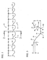
- a band saw blade embodying the present invention is indicated generally by the reference numeral 10.
- the band saw blade 10 defines a cutting direction indicated by the arrow "a", and a feed direction indicated by the arrow "b".
- the band saw blade 10 comprises a plurality of recurrent or repetitive patterns of teeth defining an eight tooth pitch pattern.
- Each pitch pattern is defined by a recurrent group of eight successive teeth indicated by the reference numerals 12, 14, 16, 18, 20, 22, 24 and 26.
- each tooth defines a respective pitch or tooth spacing P12 through P26.
- the pitch or tooth spacing is measured between the tips of adjacent teeth.
- the pitch or tooth spacing may be measured between any of numerous other corresponding points between adjacent teeth.
- Each eight tooth pitch pattern of the band saw blade 10 defines a three/five set pattern.
- a first set pattern is defined by the three successive teeth 12, 14 and 16, and a second set pattern is defined by the next five successive teeth 18, 20, 22, 24 and 26.
- the first set pattern is defined by a first unset leading tooth 12, a primary right set trailing tooth 14, and a primary left set trailing tooth 16.
- the second set pattern is defined by a first unset leading tooth 18, a primary right set trailing tooth 20, a primary left set trailing tooth 22, a secondary right set trailing tooth 24, and a secondary left set trailing tooth 26.
- FIG. 1 a first set pattern is defined by the three successive teeth 12, 14 and 16
- a second set pattern is defined by the next five successive teeth 18, 20, 22, 24 and 26.
- the first set pattern is defined by a first unset leading tooth 12, a primary right set trailing tooth 14, and a primary left set trailing tooth 16.
- the second set pattern is defined by a first unset leading tooth 18, a primary right set trailing tooth
- each unset leading tooth 12 and 18 is symmetrical about the plane of symmetry "p" of the band saw blade 10, and defines a cutting edge substantially located within a cutting plane "x" which is approximately perpendicular to the plane of symmetry "p".
- Each right set trailing tooth 14, 20 and 24 is tilted or set to the right in the drawing relative to the plane of symmetry "p" (when viewed from the cutting direction "a” of the saw blade), and defines a cutting edge substantially located within a cutting plane "y” tilted or set at an acute angle relative to the plane of symmetry "p".
- each left set trailing tooth 16, 22 and 26 is tilted or set to the left in the drawing relative to the plane of symmetry "p", and defines a cutting edge substantially located within a cutting plane "z” tilted or set an acute angle relative to the plane of symmetry "p".
- each set tooth defines substantially the same magnitude of set as the other teeth of like set direction, thus defining a "single level” set blade, and further defines the same tooth height as the other teeth of like set direction.
- the pitch of each tooth is the distance in the elongated direction of the saw blade between corresponding points of the respective tooth and the preceding tooth in the cutting direction of the saw blade.
- the pitch may be measured between the tips of adjacent teeth.
- the accumulated pitch of a tooth is the sum of the pitch distances between the respective tooth and the nearest preceding tooth of the same or like set direction in the cutting direction of the saw blade.
- the accumulated pitch of the unset leading tooth 18 is the sum of the pitch distances P14, P16 and P18, i.e., the sum of the pitch distances between the unset leading tooth 18 and the nearest preceding unset leading tooth 12 in the cutting direction "a" of the saw blade.
- the ratio of pitch to accumulated pitch for each tooth of like set direction within each set pattern increases from one tooth to the next in the direction opposite the cutting direction of the saw blade for distributing the chip load over the teeth of the saw blade.
- the ratio of pitch to accumulated pitch is greater for each secondary tooth than for the corresponding primary tooth, is greater for each tertiary tooth than for the corresponding secondary and primary teeth, and so on.
- the pitch and accumulated pitch of each tooth in the illustrated embodiment of FIG. 1 are set forth in the following table: Accumulated Ratio of Pitch to Accumulated Tooth Pitch No. Set Direction No . Pitch Pitch Pitch 22 P22 Left 0.243 0.776 0.31 24 P24 Right 0.267 0.510 0.52 26 P26 Left 0.297 0.564 0.52 12 P12 Unset 0.333 1.398 0.24 14 P14 Right 0.310 0.940 0.33 16 P16 Left 0.290 0.933 0.31 18 P18 Unset 0.275 0.875 0.31 20 P20 Right 0.258 0.823 0.31
- the specific pitch and accumulated pitch dimensions set forth in the preceding table are exemplary only, and any of numerous different dimensions may be selected depending upon the particular design criteria or other desired characteristics of the band saw blades within the teachings and scope of the present invention as defined by the claims.
- the gullet area of each tooth may be directly proportional to the accumulated pitch distance between that tooth and the next preceding tooth of like set direction, as disclosed in commonly-assigned U.S. Patent Application Serial No. 08/967,279 , now U.S. Patent No. 6,003,422 , or in its counterpart WO 9629173 .
- each tooth is dependent, in part, on the accumulated pitch of the respective tooth. Accordingly, regardless of the particular pitch dimensions selected, the ratio of pitch to accumulated pitch for teeth of the same or like set direction increases within each set pattern from one tooth to the next in the direction opposite the cutting direction of the saw blade in order to substantially evenly distribute the chip load over the teeth of the saw blade.
- each tooth defines a different pitch than every other tooth within the respective set pattern, and in accordance with the present invention defines a different pitch than every other tooth within the respective pitch pattern.
- each tooth will generate a different forcing frequency upon cutting a workpiece.
- each tooth may define a different pitch than every other tooth within the respective set pattern, but not every other tooth in the respective pitch pattern, and still achieve the function of having each tooth entering or exiting the workpiece during cutting operations generate a different forcing frequency (f) than every other tooth simultaneously entering or exiting the workpiece, and/or successively entering or exiting the workpiece.
- every tooth preferably defines a different pitch than every other tooth within the respective pitch pattern as illustrated, for example, in the table above.
- each tooth is preferably constructed in accordance with the teachings of co-pending, commonly assigned U.S. Patent Application Serial No. 09/015,122 , now U.S. Patent No. 6,167,792 B1 .
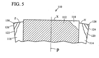
- each tooth preferably defines dual rake faces forming dual rake angles.
- a first rake face 28 defines a relatively aggressive rake angle and extends downwardly from the outermost point of the tip over only the usable portion of the tip during the life of the blade.
- the first rake face extends downwardly from the outermost point of the tip a distance "h", which is preferably within the range of about 10% through about 25% of the maximum gullet depth "D".
- a second rake face 30 extends downwardly from the first rake face 28 and defines a less aggressive rake angle than that of the first rake face in order to increase the mass of tooth material, and thus the strength and stiffness of the tooth.
- the first rake face 28 defines a first rake angle of approximately 12°
- the second rake face 30 defines a second rake angle within the range of about 7.1° through about 8.2°.
- these rake angles are only exemplary and may take any of numerous different configurations depending upon the desired characteristics of the band saw blades of the invention.
- the primary rake angle is within the range of about 8° through about 15°
- the secondary rake angle is within the range of about -5° through about 8°.
- Each tooth also defines a relatively deep gullet having a depth "D" such that the ratio of D/P is preferably within the range of about 39% through about 48%. In the exemplary embodiment of FIG. 3 , D/P is approximately 47%.
- a first flat 32 is defined at the base of each gullet, a first arcuate region 34 defined by a radius R1 is formed on one side of the first flat, a second arcuate region 36 defined by a second radius R2 is formed on the other side of the first flat, and points of tangency "T" are formed on each side of each arcuate region.
- the first flat 32 is located approximately at the set-bend plane of the teeth.
- the two arcuate surfaces 34, 36, plus the points of tangency on either side of each are, significantly increase the mass and/or volume of material at the base of the gullet (also typically the region of the set-bend plane), and in turn significantly increase the overall strength of the tooth.
- a second flat 38 extends upwardly from the second arcuate region 36 with a point of tangency "T" formed therebetween.
- a third arcuate region 40 is formed between the second flat 38 and the second rake surface 30, also with points of tangency "T” formed therebetween. The formation of the second flat 38 with arcuate portions on either side of the flat further increases the mass and/or volume of tooth material in this region, and therefore further increases the stiffness and/or strength of the tooth.
- each tooth preferably defines dual relief surfaces, including a primary relief surface 42 extending rearwardly from the tip at a primary relief angle, and a secondary relief surface 44 extending between the primary relief surface and the arcuate region 34 of the adjacent tooth at a secondary relief angle.
- the primary relief angle is preferable less than the secondary relief angle in order to increase the strength of the tooth in the tip area, and the secondary relief angle is greater than the primary relief angle in order to achieve the desired gullet depth.
- the primary relief angle is within the range of about 25° through about 35°, and preferably within the range of about 28° through about 32°, Similarly, the second relief angle is within the range of about 35° through about 55°, and preferably is within the range of about 35° through about 48°.
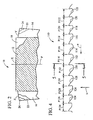
- FIG. 4 another band saw blade embodying the present invention is indicated generally by the reference numeral 110.
- the band saw blade 110 is substantially similar to the band saw blade 10 described above with reference to FIGS. 1-3 , and therefore like reference numerals preceded by the numeral 1 are used to indicate like elements.
- the primary difference between the band saw blade 110 is that it defines a ten tooth pitch pattern, and a three/seven set pattern. Otherwise, as with the previous embodiment, the ratio of pitch to accumulated pitch for each tooth of like set direction within each set pattern increases from one tooth to the next in the direction opposite the cutting direction of the saw blade for substantially evenly distributing the chip load over the teeth of the saw blade.
- each tooth defines a different pitch than every other tooth within the respective set pattern, and preferably, defines a different pitch than every other tooth within the respective pitch pattern.
- the pitch and accumulated pitch of each tooth in the embodiment of FIG. 4 are set forth in the following table: Accumulated Ratio of Pitch to Accumulated Tooth No. Pitch No.
- a further embodiment of the present invention having a ten tooth pitch pattern, and a three/seven set pattern defines the following alternative pitch distances: Accumulated Ratio of Pitch to Accumulated Tooth No. Pitch No. Set Direction Pitch Pitch Pitch 112 P112 Unset 0.515 2.849 0.18 114 P114 Right 0.494 1.483 0.33 116 P116 Left 0.454 1.463 0.31 118 P118 Unset 0.434 1.382 0.31 120 P120 Right 0.391 1.279 0.30 122 P122 Left 0.372 1.197 0.31 124 P124 Right 0.333 0.705 0.47 126 P126 Left 0.351 0.681 0.51 128 P128 Right 0.413 0.764 0.54 130 P130 Left 0.474 0.887 0.53
Landscapes
- Engineering & Computer Science (AREA)
- Mechanical Engineering (AREA)
- Life Sciences & Earth Sciences (AREA)
- Wood Science & Technology (AREA)
- Forests & Forestry (AREA)
- Sawing (AREA)
- Package Frames And Binding Bands (AREA)
- Polishing Bodies And Polishing Tools (AREA)
- Harvester Elements (AREA)
- Toys (AREA)
Claims (18)
- Bandsägeblatt (10) zum Schneiden eines Werkstücks und Erzeugen einer Spanbelastung auf jedem Zahn beim Schneiden des Werkstücks, umfassend:- eine Vielzahl von Zähnen, die ein Teilungsmuster von mindestens acht Zähnen (12, 14, 16, 18, 20, 22, 24, 26) und Segmentmuster (12, 14, 16; 18, 20, 22, 24, 26) innerhalb jedes Teilungsmusters definieren; wobei jedes Segmentmuster durch einen angesetzten Vorschneidzahn (12; 18) und eine Vielzahl von versetzten Nachschneidzähnen (14, 16; 20, 22, 24, 26) definiert ist, und jeder versetzte Nachschneidzahn in einer jeweiligen Segmentrichtung im Verhältnis zum angesetzten Vorschneidzahn versetzt ist; und jeder versetzte Nachschneidzahn definiert im Wesentlichen die gleiche Segmentgröße wie jeder zweite gleiche Segmentzahn innerhalb des jeweiligen Segmentmusters;- wobei jeder Zahn innerhalb jedes Segmentmusters eine Teilung zwischen dem jeweiligen Zahn und dem vorherigen Zahn in einer Schnittrichtung des Sägeblatts und eine kumulierte Teilung zwischen dem jeweiligen Zahn und einem vorherigen Zahn der gleichen Segmentrichtung in der Schnittrichtung des Sägeblatts definiert; und dadurch gekennzeichnet, dass- das Verhältnis von Teilung zu kumulierter Teilung für jeden Zahn der gleichen Segmentrichtung innerhalb jedes Segmentmusters von einem Zahn zum anderen in der Richtung, die der Schnittrichtung des Sägeblatts (10) entgegengesetzt ist, ansteigt, um die Spanbelastung auf die Zähne des Sägeblatts (10) zu verteilen.
- Bandsägeblatt nach Anspruch 1, wobei die Vielzahl von Zähnen ein geradzahliges Teilungsmuster von mindestens acht Zähnen und ungeradzahlige Segmentmuster innerhalb jedes Teilungsmusters definiert.
- Bandsägeblatt nach Anspruch 2, wobei die Vielzahl von Zähnen ein Acht-Zahn-Teilungsmuster und ein Drei/Fünf-Segmentmuster definiert.
- Bandsägeblatt nach Anspruch 2, wobei die Vielzahl von Zähnen ein Zehn-Zahn-Teilungsmuster und ein Drei/Sieben-Segmentmuster definiert.
- Bandsägeblatt nach Anspruch 1, wobei jeder Zahn eine andere Teilung definiert als jeder andere Zahn in seinem jeweiligen Teilungsmuster.
- Bandsägeblatt nach Anspruch 1, wobei jeder Zahn eine andere Teilung definiert als jeder andere Zahn innerhalb seines jeweiligen Segmentmusters.
- Bandsägeblatt nach Anspruch 1, wobei jedes Segmentmuster eine Vielzahl von Gruppen aus Rechtssegmentzähnen (14; 20, 24) und eine Vielzahl von Gruppen aus Linkssegmentzähnen (16; 22, 26) umfasst.
- Bandsägeblatt nach Anspruch 7, wobei mindestens eine Gruppe von Rechtssegmentzähnen (14; 20, 44) einen primären Rechtssegmentzahn (14; 20), einen sekundären Rechtssegmentzahn (24) und einen tertiären Rechtssegmentzahn umfasst.
- Bandsägeblatt nach Anspruch 7, wobei mindestens eine Gruppe von Linkssegmentzähnen (16; 22, 46) einen primären Linkssegmentzahn (16; 22), einen sekundären Linkssegmentzahn (26) und einen tertiären Linkssegmentzahn umfasst.
- Bandsägeblatt nach Anspruch 1, wobei jeder Zahn eine andere Druckfrequenz aufweist als jeder zweite Zahn in seinem jeweiligen Segmentmuster.
- Bandsägeblatt nach Anspruch 1, wobei jeder Zahn eine andere Druckfrequenz aufweist als jeder zweite Zahn innerhalb seines jeweiligen Teilungsmusters.
- Bandsägeblatt nach Anspruch 1, umfassend eine Vielzahl von angesetzten Räumzähnen innerhalb jedes Teilungsmusters und eine Vielzahl von versetzten Nachschneidzähnen, die jeweils einem angesetzten Räumzahn innerhalb jedes Segmentmusters folgen.
- Bandsägeblatt nach Anspruch 1, wobei jeder der versetzten Zähne ungefähr die gleiche Zahnhöhe definiert wie jeder zweite Zahn innerhalb des jeweiligen Segmentmusters.
- Bandsägeblatt nach Anspruch 1, wobei jeder der versetzten Zähne ungefähr die gleiche Segmentgröße definiert wie jeder zweite gleiche Segmentzahn innerhalb des jeweiligen Teilungsmusters.
- Bandsägeblatt zum Schneiden eines Werkstücks und Erzeugen einer Spanbelastung auf jedem Zahn beim Schneiden des Werkstücks, umfassend:- periodische Muster aus mindestens acht Zähnen pro Muster (12, 14, 16, 18, 20, 22, 24, 26);- mindestens zwei Segmentmuster (12, 14, 16; 18, 20, 22, 24, 26) innerhalb jedes periodischen Musters aus mindestens acht Zähnen, wobei jedes Segmentmuster einen angesetzten Vorschneidzahl (12; 18) und eine Vielzahl von versetzten Nachschneidzähnen (14, 16; 20, 22, 24, 26) umfasst, und wobei jeder versetzte Nachschneidzahn in eine jeweilige Segmentrichtung im Verhältnis zum angesetzten Vorschneidzahn versetzt ist und im Wesentlichen die gleiche Segmentgröße wie jeder zweite Zahn der gleichen Segmentrichtung innerhalb des jeweiligen Segmentmusters definiert; und- wobei jeder Zahn eine Teilung zwischen dem jeweiligen Zahn und dem vorherigen Zahn in einer Schnittrichtung des Sägeblatts definiert, und jeder Zahn eine andere Teilung als jeder zweite Zahn in dem jeweiligen Segmentmuster definiert, um dadurch eine andere Druckfrequenz für jeden Zahn im Vergleich zu jedem zweiten Zahn in dem jeweiligen Segmentmuster zu definieren, dadurch gekennzeichnet, dass- die mindestens zwei Segmentmuster ein erstes Segmentmuster von drei aufeinander folgenden Zähnen und ein zweites Segmentmuster von fünf oder sieben aufeinander folgenden Zähnen umfassen.
- Bandsägeblatt nach Anspruch 15, wobei jeder der versetzten Zähne ungefähr die gleiche Segmentgröße definiert wie jeder zweite gleiche Segmentzahn innerhalb des jeweiligen periodischen Musters aus mindestens acht Zähnen.
- Bandsägeblatt nach Anspruch 15, wobei jeder der versetzten Zähne ungefähr die gleiche Zahnhöhe definiert wie jeder zweite gleiche Segmentzahn innerhalb des jeweiligen Segmentmusters.
- Bandsägeblatt nach Anspruch 15, wobei jeder Zahn eine andere Teilung definiert als jeder zweite Zahn in dem jeweiligen periodischen Muster aus mindestens acht Zähnen, um dadurch für jeden Zahn im Vergleich zu jedem zweiten Zahn in dem jeweiligen periodischen Muster eine andere Druckfrequenz zu definieren.
Applications Claiming Priority (3)
| Application Number | Priority Date | Filing Date | Title |
|---|---|---|---|
| US435108 | 1989-11-13 | ||
| US09/435,108 US6276248B1 (en) | 1999-11-05 | 1999-11-05 | Band saw blade having reduced noise and uniform tooth loading characteristics |
| PCT/US2000/041906 WO2001032340A2 (en) | 1999-11-05 | 2000-11-03 | Band saw blade having reduced noise and uniform tooth loading characteristics |
Publications (3)
| Publication Number | Publication Date |
|---|---|
| EP1237674A2 EP1237674A2 (de) | 2002-09-11 |
| EP1237674A4 EP1237674A4 (de) | 2006-05-31 |
| EP1237674B1 true EP1237674B1 (de) | 2009-03-04 |
Family
ID=23727020
Family Applications (1)
| Application Number | Title | Priority Date | Filing Date |
|---|---|---|---|
| EP00991945A Expired - Lifetime EP1237674B1 (de) | 1999-11-05 | 2000-11-03 | Bandsägeblatt mit verringerter rausch- und gleichmässiger zahnbelastungscharakteristik |
Country Status (13)
| Country | Link |
|---|---|
| US (1) | US6276248B1 (de) |
| EP (1) | EP1237674B1 (de) |
| JP (1) | JP2003527246A (de) |
| KR (1) | KR100516040B1 (de) |
| AT (1) | ATE424269T1 (de) |
| AU (1) | AU3642501A (de) |
| BR (1) | BR0014885A (de) |
| CA (1) | CA2389792C (de) |
| DE (1) | DE60041712D1 (de) |
| ES (1) | ES2323848T3 (de) |
| MX (1) | MXPA02004475A (de) |
| TW (1) | TW496805B (de) |
| WO (1) | WO2001032340A2 (de) |
Families Citing this family (38)
| Publication number | Priority date | Publication date | Assignee | Title |
|---|---|---|---|---|
| US6601495B2 (en) * | 2000-07-18 | 2003-08-05 | American Saw & Mfg. Co., Inc. | Structural saw blade |
| DE10047212A1 (de) * | 2000-09-23 | 2002-04-11 | C & E Fein Gmbh & Co Kg | Sägeblatt |
| US7036417B2 (en) | 2001-11-13 | 2006-05-02 | William George Alton | Bandsaw blade with cutting extensions |
| US7178441B2 (en) * | 2002-12-20 | 2007-02-20 | Kapman Ab | Versatile bandsaw blade |
| US6939092B2 (en) * | 2003-06-18 | 2005-09-06 | Irwin Industrial Tool Company | Sheet metal hole cutter |
| US7131365B2 (en) * | 2003-09-16 | 2006-11-07 | Irwin Industrial Tool Company | Multi-chip facet cutting saw blade and related method |
| AU2005231308A1 (en) * | 2004-03-26 | 2005-10-20 | Black & Decker Inc. | Tooth form design for reciprocating saw blade |
| US7658136B2 (en) * | 2004-12-22 | 2010-02-09 | Black & Decker Inc. | Hole saw blade |
| US20050211046A1 (en) * | 2004-03-26 | 2005-09-29 | Thomas Rickey J | Tooth form design for reciprocating saw blade |
| US7225714B2 (en) * | 2004-12-22 | 2007-06-05 | Black & Decker Inc. | Tooth form design for reciprocating saw blade |
| JP4102817B2 (ja) * | 2004-08-19 | 2008-06-18 | 株式会社アマダ | 帯鋸刃 |
| US7174823B2 (en) * | 2004-09-22 | 2007-02-13 | Irwin Industrial Tool Company | Saw blade having increased tooth stiffness and resistance to fatigue failure |
| US7264428B2 (en) * | 2005-05-19 | 2007-09-04 | Irwin Industrial Tool Company | Hole saw and cutter |
| US20070199416A1 (en) * | 2006-02-25 | 2007-08-30 | Cook James T | Band saw blade |
| WO2007098276A2 (en) * | 2006-02-25 | 2007-08-30 | James Timothy Cook | Band saw blade |
| US7913601B2 (en) * | 2006-04-28 | 2011-03-29 | Simonds International Corporation | Enhanced performance saw blade toothform pattern |
| RU2010140369A (ru) * | 2008-03-04 | 2012-04-10 | Ирвин Индастриал Тул Компани (Us) | Инструменты, имеющие рабочие поверхности из уплотненного порошкового металла, и способ |
| DE102008045733B4 (de) * | 2008-09-04 | 2010-11-04 | J.N. Eberle & Cie Gmbh | Bandsägeblatt mit noppenartigen Ausbuchtungen |
| JP5508531B2 (ja) * | 2009-07-27 | 2014-06-04 | アーウィン インダストリアル トゥール カンパニー | 単レベル目立てパターン及び複レベル目立てパターンを併含するピッチパターンに従うソーブレード及びそれに関連する方法 |
| JP5684484B2 (ja) * | 2010-03-04 | 2015-03-11 | 株式会社アマダ | 帯鋸刃 |
| US10189099B2 (en) | 2010-04-22 | 2019-01-29 | Milwaukee Electric Tool Corporation | Saw Blade |
| WO2011133864A2 (en) | 2010-04-22 | 2011-10-27 | Milwaukee Electric Tool Corporation | Saw blade |
| US9375796B2 (en) | 2010-05-07 | 2016-06-28 | Irwin Industrial Tool Company | Saw blade with robust tooth form |
| USD642028S1 (en) | 2010-05-21 | 2011-07-26 | Irwin Industrial Tool Company | Reciprocating saw blade |
| US9248518B2 (en) | 2010-06-30 | 2016-02-02 | Irwin Industrial Tool Company | Saw blade tooth form for abusive cutting applications |
| CA2749666C (en) | 2010-08-20 | 2014-07-15 | Milwaukee Electric Tool Corporation | Reciprocating saw blade |
| USD841417S1 (en) | 2011-04-22 | 2019-02-26 | Milwaukee Electric Tool Corporation | Saw blade |
| JP5903345B2 (ja) * | 2012-07-17 | 2016-04-13 | 株式会社アマダホールディングス | 鋸刃各歯の最適配置方法及び鋸刃 |
| CA2845968C (en) | 2013-03-14 | 2016-07-26 | Irwin Industrial Tool Company | Reciprocating saw blade with curved cutting edge |
| US10906111B2 (en) | 2013-07-29 | 2021-02-02 | The M.K. Morse Company | Method of using a cutting blade |
| USD732914S1 (en) * | 2013-11-13 | 2015-06-30 | Irwin Industrial Tool Company | Reciprocating saw blade |
| USD725450S1 (en) * | 2013-11-13 | 2015-03-31 | Irwin Industrial Tool Company | Reciprocating saw blade |
| US20160008899A1 (en) * | 2014-07-14 | 2016-01-14 | Roy A. Hunter | Variable Pitch Blade |
| US10112245B2 (en) | 2015-04-20 | 2018-10-30 | Irwin Industrial Tool Company | Band saw blade |
| US10625353B2 (en) * | 2015-09-01 | 2020-04-21 | Wood-Mizer, Llc | Wood cutting band saw blade having reduced kerf dust |
| US10213854B2 (en) | 2016-11-14 | 2019-02-26 | Irwin Industrial Tool Company | Band saw blade |
| US11413693B2 (en) | 2017-05-16 | 2022-08-16 | Milwaukee Electric Tool Corporation | Saw blade |
| US10537951B2 (en) | 2017-08-16 | 2020-01-21 | Black & Decker Inc. | Band saw blade for cutting structural workpieces |
Citations (1)
| Publication number | Priority date | Publication date | Assignee | Title |
|---|---|---|---|---|
| WO1996029173A1 (en) * | 1995-03-23 | 1996-09-26 | American Saw And Manufacturing Company | Synchronized variable tooth arrangements for saws |
Family Cites Families (19)
| Publication number | Priority date | Publication date | Assignee | Title |
|---|---|---|---|---|
| US603128A (en) * | 1898-04-26 | Hack-saw | ||
| US2568870A (en) | 1945-10-31 | 1951-09-25 | Lerned F Ronan | Saw |
| US3292674A (en) * | 1964-01-20 | 1966-12-20 | High Duty Saws Ltd | Saws |
| US4179967A (en) | 1978-08-28 | 1979-12-25 | Stanadyne, Inc. | Variable tooth saw blade |
| USRE31433E (en) | 1978-08-28 | 1983-11-01 | Capewell Manufacturing Company | Variable tooth saw blade |
| US4292871A (en) | 1979-02-01 | 1981-10-06 | The L. S. Starrett Company | Welded edge band saw tooth geometry |
| JPS57181801A (en) * | 1981-05-01 | 1982-11-09 | Uichi Miyawaki | Saw and manufacture of saw |
| JPS58137520A (ja) * | 1982-01-13 | 1983-08-16 | Amada Co Ltd | 鋸刃 |
| DE3307170C2 (de) | 1983-03-01 | 1986-08-14 | Wilhelm H. Kullmann WIKUS-Sägenfabrik, 3509 Spangenberg | Sägeblatt und Verfahren zu seiner Herstellung |
| CA1277573C (en) * | 1985-04-03 | 1990-12-11 | Sumio Yoshida | Saw blade |
| US5018421A (en) | 1988-04-07 | 1991-05-28 | Armstrong-Blum Manufacturing Company, Ltd. | Saw blade tooth geometry |
| IT1237867B (it) | 1988-12-07 | 1993-06-18 | Lama di sega | |
| DE9206000U1 (de) | 1992-01-10 | 1992-07-30 | Wilhelm H. Kullmann WIKUS-Sägenfabrik, 3509 Spangenberg | Sägeblatt |
| US5606900A (en) | 1992-05-11 | 1997-03-04 | The L.S. Starrett Company | Variable height, high performance, bandsaw blade and method of manufacture therefor |
| US5331876A (en) * | 1992-07-30 | 1994-07-26 | Sandvik Ab | Saw blade for cutting metal |
| US5477763A (en) | 1993-01-12 | 1995-12-26 | Wikus-Sagenfabrik, Wilhelm H. Kullmann | Saw blade |
| US5868058A (en) | 1993-07-22 | 1999-02-09 | Manufacture Forezienne De Lames De Scies S.A. | Log mill band-saw blade for initial processing of timber and derivatives thereof |
| US5410935A (en) | 1993-11-01 | 1995-05-02 | American Saw & Mfg. Company | Band saw blade |
| US5501129A (en) | 1994-09-27 | 1996-03-26 | Armstrong-Blum Manufacturing Company | All purpose saw blade |
-
1999
- 1999-11-05 US US09/435,108 patent/US6276248B1/en not_active Expired - Lifetime
-
2000
- 2000-10-27 TW TW089122653A patent/TW496805B/zh not_active IP Right Cessation
- 2000-11-03 AU AU36425/01A patent/AU3642501A/en not_active Abandoned
- 2000-11-03 DE DE60041712T patent/DE60041712D1/de not_active Expired - Lifetime
- 2000-11-03 MX MXPA02004475A patent/MXPA02004475A/es active IP Right Grant
- 2000-11-03 EP EP00991945A patent/EP1237674B1/de not_active Expired - Lifetime
- 2000-11-03 AT AT00991945T patent/ATE424269T1/de active
- 2000-11-03 KR KR10-2002-7005841A patent/KR100516040B1/ko not_active Expired - Fee Related
- 2000-11-03 JP JP2001534534A patent/JP2003527246A/ja active Pending
- 2000-11-03 CA CA002389792A patent/CA2389792C/en not_active Expired - Fee Related
- 2000-11-03 BR BR0014885-7A patent/BR0014885A/pt not_active IP Right Cessation
- 2000-11-03 ES ES00991945T patent/ES2323848T3/es not_active Expired - Lifetime
- 2000-11-03 WO PCT/US2000/041906 patent/WO2001032340A2/en not_active Ceased
Patent Citations (1)
| Publication number | Priority date | Publication date | Assignee | Title |
|---|---|---|---|---|
| WO1996029173A1 (en) * | 1995-03-23 | 1996-09-26 | American Saw And Manufacturing Company | Synchronized variable tooth arrangements for saws |
Also Published As
| Publication number | Publication date |
|---|---|
| KR100516040B1 (ko) | 2005-09-26 |
| WO2001032340A2 (en) | 2001-05-10 |
| WO2001032340A3 (en) | 2001-09-27 |
| AU3642501A (en) | 2001-05-14 |
| CA2389792C (en) | 2006-10-03 |
| CA2389792A1 (en) | 2001-05-10 |
| MXPA02004475A (es) | 2004-09-10 |
| JP2003527246A (ja) | 2003-09-16 |
| US6276248B1 (en) | 2001-08-21 |
| BR0014885A (pt) | 2003-07-29 |
| EP1237674A2 (de) | 2002-09-11 |
| ES2323848T3 (es) | 2009-07-27 |
| TW496805B (en) | 2002-08-01 |
| EP1237674A4 (de) | 2006-05-31 |
| ATE424269T1 (de) | 2009-03-15 |
| KR20030017460A (ko) | 2003-03-03 |
| DE60041712D1 (de) | 2009-04-16 |
Similar Documents
| Publication | Publication Date | Title |
|---|---|---|
| EP1237674B1 (de) | Bandsägeblatt mit verringerter rausch- und gleichmässiger zahnbelastungscharakteristik | |
| AU676100B2 (en) | Improved band saw blade | |
| US5603252A (en) | Saw blade | |
| EP1324863B1 (de) | Sägeblatt zum sägen von stahlprofilen | |
| CA2520545C (en) | Saw blade having increased tooth stiffness and resistance to fatigue failure | |
| US4557172A (en) | Saw blade | |
| EP0704269B1 (de) | Allzwecksägeblatt | |
| JP4447665B2 (ja) | 改良された帯鋸 | |
| US7913601B2 (en) | Enhanced performance saw blade toothform pattern | |
| US6520722B2 (en) | Asymmetrical cutting tool tooth form | |
| US7036417B2 (en) | Bandsaw blade with cutting extensions | |
| JPH0639631A (ja) | 鋸 刃 | |
| US20090126205A1 (en) | Saw Blade With Round Cutting Edges | |
| EP0849022B1 (de) | Sägeblatt mit sich wiederholenden Zahngruppen | |
| JPH10202426A (ja) | 鋸 刃 |
Legal Events
| Date | Code | Title | Description |
|---|---|---|---|
| PUAI | Public reference made under article 153(3) epc to a published international application that has entered the european phase |
Free format text: ORIGINAL CODE: 0009012 |
|
| 17P | Request for examination filed |
Effective date: 20020531 |
|
| AK | Designated contracting states |
Kind code of ref document: A2 Designated state(s): AT BE CH CY DE DK ES FI FR GB GR IE IT LI LU MC NL PT SE TR |
|
| AX | Request for extension of the european patent |
Free format text: AL;LT;LV;MK;RO;SI |
|
| A4 | Supplementary search report drawn up and despatched |
Effective date: 20060421 |
|
| 17Q | First examination report despatched |
Effective date: 20060822 |
|
| GRAP | Despatch of communication of intention to grant a patent |
Free format text: ORIGINAL CODE: EPIDOSNIGR1 |
|
| GRAS | Grant fee paid |
Free format text: ORIGINAL CODE: EPIDOSNIGR3 |
|
| GRAA | (expected) grant |
Free format text: ORIGINAL CODE: 0009210 |
|
| AK | Designated contracting states |
Kind code of ref document: B1 Designated state(s): AT BE CH CY DE DK ES FI FR GB GR IE IT LI LU MC NL PT SE TR |
|
| REG | Reference to a national code |
Ref country code: GB Ref legal event code: FG4D |
|
| REG | Reference to a national code |
Ref country code: CH Ref legal event code: EP |
|
| REG | Reference to a national code |
Ref country code: IE Ref legal event code: FG4D |
|
| REF | Corresponds to: |
Ref document number: 60041712 Country of ref document: DE Date of ref document: 20090416 Kind code of ref document: P |
|
| REG | Reference to a national code |
Ref country code: SE Ref legal event code: TRGR |
|
| REG | Reference to a national code |
Ref country code: ES Ref legal event code: FG2A Ref document number: 2323848 Country of ref document: ES Kind code of ref document: T3 |
|
| PG25 | Lapsed in a contracting state [announced via postgrant information from national office to epo] |
Ref country code: FI Free format text: LAPSE BECAUSE OF FAILURE TO SUBMIT A TRANSLATION OF THE DESCRIPTION OR TO PAY THE FEE WITHIN THE PRESCRIBED TIME-LIMIT Effective date: 20090304 Ref country code: NL Free format text: LAPSE BECAUSE OF FAILURE TO SUBMIT A TRANSLATION OF THE DESCRIPTION OR TO PAY THE FEE WITHIN THE PRESCRIBED TIME-LIMIT Effective date: 20090304 |
|
| NLV1 | Nl: lapsed or annulled due to failure to fulfill the requirements of art. 29p and 29m of the patents act | ||
| PG25 | Lapsed in a contracting state [announced via postgrant information from national office to epo] |
Ref country code: BE Free format text: LAPSE BECAUSE OF FAILURE TO SUBMIT A TRANSLATION OF THE DESCRIPTION OR TO PAY THE FEE WITHIN THE PRESCRIBED TIME-LIMIT Effective date: 20090304 |
|
| PG25 | Lapsed in a contracting state [announced via postgrant information from national office to epo] |
Ref country code: PT Free format text: LAPSE BECAUSE OF FAILURE TO SUBMIT A TRANSLATION OF THE DESCRIPTION OR TO PAY THE FEE WITHIN THE PRESCRIBED TIME-LIMIT Effective date: 20090818 |
|
| PLBE | No opposition filed within time limit |
Free format text: ORIGINAL CODE: 0009261 |
|
| STAA | Information on the status of an ep patent application or granted ep patent |
Free format text: STATUS: NO OPPOSITION FILED WITHIN TIME LIMIT |
|
| PG25 | Lapsed in a contracting state [announced via postgrant information from national office to epo] |
Ref country code: DK Free format text: LAPSE BECAUSE OF FAILURE TO SUBMIT A TRANSLATION OF THE DESCRIPTION OR TO PAY THE FEE WITHIN THE PRESCRIBED TIME-LIMIT Effective date: 20090304 |
|
| 26N | No opposition filed |
Effective date: 20091207 |
|
| PG25 | Lapsed in a contracting state [announced via postgrant information from national office to epo] |
Ref country code: MC Free format text: LAPSE BECAUSE OF NON-PAYMENT OF DUE FEES Effective date: 20091130 |
|
| REG | Reference to a national code |
Ref country code: CH Ref legal event code: PL |
|
| PG25 | Lapsed in a contracting state [announced via postgrant information from national office to epo] |
Ref country code: LI Free format text: LAPSE BECAUSE OF NON-PAYMENT OF DUE FEES Effective date: 20091130 Ref country code: CH Free format text: LAPSE BECAUSE OF NON-PAYMENT OF DUE FEES Effective date: 20091130 Ref country code: GR Free format text: LAPSE BECAUSE OF FAILURE TO SUBMIT A TRANSLATION OF THE DESCRIPTION OR TO PAY THE FEE WITHIN THE PRESCRIBED TIME-LIMIT Effective date: 20090605 Ref country code: IE Free format text: LAPSE BECAUSE OF NON-PAYMENT OF DUE FEES Effective date: 20091103 |
|
| PG25 | Lapsed in a contracting state [announced via postgrant information from national office to epo] |
Ref country code: LU Free format text: LAPSE BECAUSE OF NON-PAYMENT OF DUE FEES Effective date: 20091103 |
|
| PGFP | Annual fee paid to national office [announced via postgrant information from national office to epo] |
Ref country code: SE Payment date: 20110512 Year of fee payment: 11 |
|
| PG25 | Lapsed in a contracting state [announced via postgrant information from national office to epo] |
Ref country code: TR Free format text: LAPSE BECAUSE OF FAILURE TO SUBMIT A TRANSLATION OF THE DESCRIPTION OR TO PAY THE FEE WITHIN THE PRESCRIBED TIME-LIMIT Effective date: 20090304 |
|
| PGFP | Annual fee paid to national office [announced via postgrant information from national office to epo] |
Ref country code: AT Payment date: 20110512 Year of fee payment: 11 |
|
| PG25 | Lapsed in a contracting state [announced via postgrant information from national office to epo] |
Ref country code: CY Free format text: LAPSE BECAUSE OF FAILURE TO SUBMIT A TRANSLATION OF THE DESCRIPTION OR TO PAY THE FEE WITHIN THE PRESCRIBED TIME-LIMIT Effective date: 20090304 |
|
| PGFP | Annual fee paid to national office [announced via postgrant information from national office to epo] |
Ref country code: IT Payment date: 20110516 Year of fee payment: 11 |
|
| PGFP | Annual fee paid to national office [announced via postgrant information from national office to epo] |
Ref country code: ES Payment date: 20111124 Year of fee payment: 12 |
|
| REG | Reference to a national code |
Ref country code: SE Ref legal event code: EUG |
|
| PG25 | Lapsed in a contracting state [announced via postgrant information from national office to epo] |
Ref country code: SE Free format text: LAPSE BECAUSE OF NON-PAYMENT OF DUE FEES Effective date: 20111104 |
|
| REG | Reference to a national code |
Ref country code: AT Ref legal event code: MM01 Ref document number: 424269 Country of ref document: AT Kind code of ref document: T Effective date: 20111103 |
|
| PG25 | Lapsed in a contracting state [announced via postgrant information from national office to epo] |
Ref country code: AT Free format text: LAPSE BECAUSE OF NON-PAYMENT OF DUE FEES Effective date: 20111103 |
|
| PG25 | Lapsed in a contracting state [announced via postgrant information from national office to epo] |
Ref country code: IT Free format text: LAPSE BECAUSE OF NON-PAYMENT OF DUE FEES Effective date: 20121103 |
|
| REG | Reference to a national code |
Ref country code: ES Ref legal event code: FD2A Effective date: 20140516 |
|
| PG25 | Lapsed in a contracting state [announced via postgrant information from national office to epo] |
Ref country code: ES Free format text: LAPSE BECAUSE OF NON-PAYMENT OF DUE FEES Effective date: 20121104 |
|
| REG | Reference to a national code |
Ref country code: FR Ref legal event code: PLFP Year of fee payment: 16 |
|
| REG | Reference to a national code |
Ref country code: FR Ref legal event code: PLFP Year of fee payment: 17 |
|
| PGFP | Annual fee paid to national office [announced via postgrant information from national office to epo] |
Ref country code: DE Payment date: 20161123 Year of fee payment: 17 Ref country code: GB Payment date: 20161128 Year of fee payment: 17 |
|
| REG | Reference to a national code |
Ref country code: FR Ref legal event code: PLFP Year of fee payment: 18 |
|
| PGFP | Annual fee paid to national office [announced via postgrant information from national office to epo] |
Ref country code: FR Payment date: 20170918 Year of fee payment: 18 |
|
| REG | Reference to a national code |
Ref country code: DE Ref legal event code: R119 Ref document number: 60041712 Country of ref document: DE |
|
| GBPC | Gb: european patent ceased through non-payment of renewal fee |
Effective date: 20171103 |
|
| PG25 | Lapsed in a contracting state [announced via postgrant information from national office to epo] |
Ref country code: DE Free format text: LAPSE BECAUSE OF NON-PAYMENT OF DUE FEES Effective date: 20180602 |
|
| PG25 | Lapsed in a contracting state [announced via postgrant information from national office to epo] |
Ref country code: GB Free format text: LAPSE BECAUSE OF NON-PAYMENT OF DUE FEES Effective date: 20171103 |
|
| PG25 | Lapsed in a contracting state [announced via postgrant information from national office to epo] |
Ref country code: FR Free format text: LAPSE BECAUSE OF NON-PAYMENT OF DUE FEES Effective date: 20181130 |