EP1237505B1 - System zum einbringen eines harnröhrenstents - Google Patents
System zum einbringen eines harnröhrenstents Download PDFInfo
- Publication number
- EP1237505B1 EP1237505B1 EP00988796A EP00988796A EP1237505B1 EP 1237505 B1 EP1237505 B1 EP 1237505B1 EP 00988796 A EP00988796 A EP 00988796A EP 00988796 A EP00988796 A EP 00988796A EP 1237505 B1 EP1237505 B1 EP 1237505B1
- Authority
- EP
- European Patent Office
- Prior art keywords
- stent
- mantle
- locating
- body cavity
- elongated member
- Prior art date
- Legal status (The legal status is an assumption and is not a legal conclusion. Google has not performed a legal analysis and makes no representation as to the accuracy of the status listed.)
- Expired - Lifetime
Links
- 238000003780 insertion Methods 0.000 claims description 14
- 230000037431 insertion Effects 0.000 claims description 14
- 210000003708 urethra Anatomy 0.000 abstract description 17
- 210000005070 sphincter Anatomy 0.000 abstract description 8
- 206010004446 Benign prostatic hyperplasia Diseases 0.000 abstract description 6
- 208000004403 Prostatic Hyperplasia Diseases 0.000 abstract description 6
- 210000003205 muscle Anatomy 0.000 abstract description 6
- 239000000463 material Substances 0.000 description 4
- 238000010276 construction Methods 0.000 description 3
- 238000000034 method Methods 0.000 description 3
- 210000002307 prostate Anatomy 0.000 description 3
- 238000001356 surgical procedure Methods 0.000 description 3
- 238000002574 cystoscopy Methods 0.000 description 2
- 230000004807 localization Effects 0.000 description 2
- 238000004904 shortening Methods 0.000 description 2
- 238000002604 ultrasonography Methods 0.000 description 2
- 206010021639 Incontinence Diseases 0.000 description 1
- 206010030113 Oedema Diseases 0.000 description 1
- 241000722921 Tulipa gesneriana Species 0.000 description 1
- XSQUKJJJFZCRTK-UHFFFAOYSA-N Urea Chemical compound NC(N)=O XSQUKJJJFZCRTK-UHFFFAOYSA-N 0.000 description 1
- 206010046555 Urinary retention Diseases 0.000 description 1
- 230000003213 activating effect Effects 0.000 description 1
- 230000004913 activation Effects 0.000 description 1
- 238000004458 analytical method Methods 0.000 description 1
- 238000005452 bending Methods 0.000 description 1
- 230000009286 beneficial effect Effects 0.000 description 1
- 239000004202 carbamide Substances 0.000 description 1
- 230000006835 compression Effects 0.000 description 1
- 238000007906 compression Methods 0.000 description 1
- 238000002681 cryosurgery Methods 0.000 description 1
- 230000007812 deficiency Effects 0.000 description 1
- 230000000694 effects Effects 0.000 description 1
- 210000003238 esophagus Anatomy 0.000 description 1
- 239000012634 fragment Substances 0.000 description 1
- 210000000936 intestine Anatomy 0.000 description 1
- 230000000149 penetrating effect Effects 0.000 description 1
- 239000002861 polymer material Substances 0.000 description 1
- 230000002250 progressing effect Effects 0.000 description 1
- 239000007787 solid Substances 0.000 description 1
- 229910001220 stainless steel Inorganic materials 0.000 description 1
- 239000010935 stainless steel Substances 0.000 description 1
- 238000012360 testing method Methods 0.000 description 1
- 238000002560 therapeutic procedure Methods 0.000 description 1
- 210000003437 trachea Anatomy 0.000 description 1
- 238000012546 transfer Methods 0.000 description 1
- 230000002485 urinary effect Effects 0.000 description 1
- 201000002327 urinary tract obstruction Diseases 0.000 description 1
- 230000000007 visual effect Effects 0.000 description 1
- 238000007794 visualization technique Methods 0.000 description 1
- 239000011800 void material Substances 0.000 description 1
Images


Classifications
-
- A—HUMAN NECESSITIES
- A61—MEDICAL OR VETERINARY SCIENCE; HYGIENE
- A61F—FILTERS IMPLANTABLE INTO BLOOD VESSELS; PROSTHESES; DEVICES PROVIDING PATENCY TO, OR PREVENTING COLLAPSING OF, TUBULAR STRUCTURES OF THE BODY, e.g. STENTS; ORTHOPAEDIC, NURSING OR CONTRACEPTIVE DEVICES; FOMENTATION; TREATMENT OR PROTECTION OF EYES OR EARS; BANDAGES, DRESSINGS OR ABSORBENT PADS; FIRST-AID KITS
- A61F2/00—Filters implantable into blood vessels; Prostheses, i.e. artificial substitutes or replacements for parts of the body; Appliances for connecting them with the body; Devices providing patency to, or preventing collapsing of, tubular structures of the body, e.g. stents
- A61F2/95—Instruments specially adapted for placement or removal of stents or stent-grafts
- A61F2/9517—Instruments specially adapted for placement or removal of stents or stent-grafts handle assemblies therefor
Definitions
- the invention relates to the field of treatment of body cavities with stents, for instance urological stents, and more particularly to such stents which are used in the treatment of prostatic hyperplasia.
- the present invention relates to a device for inserting and/or locating a stent in a body cavity, especially the prostatic stent in a human male urethra to treat the prostatic hyperplasia therein. It also is possible to utilize the device of the present invention for the placing of stents in other body cavities, such as the esophagus, the biliary passage, the intestine, or the trachea.
- Prostatic stents are used to keep the prostatic lobes apart, preventing the compression of the urethra and allowing free urinary flow after different types of prostatic thermal therapy methods (e.g., VLAP, TUMT, TULIP, ILC, TUNA, HIFY, cryosurgery etc .) have been utilized to treat benign prostatic hyperplasia./ Such stents may also be used in provisional treatment of patients with urinary retention who are waiting for prostatic surgery or to test the effect of surgical treatment in the case of lower urinary tract obstruction induced by benign prostatic hyperplasia. As the oedema subsides, the stent can be withdrawn. If the stent material is bioabsorbable, the prostatic stent gradually loses its strength after a determinate time period, and the small fragments of the stent exit the body through urea.
- prostatic thermal therapy methods e.g., VLAP, TUMT, TULIP, ILC, TUNA
- the device may comprise an outer elongate tubular mantle having first and second ends, and an elongate member placed inside the mantle, having first and second end portions protruding the respective ends of the mantle. Further, the device may comprise means for preventing said stent from sliding off of the member, and means for locating an obstacle in the body cavity.
- the device of the present invention is used as an applicator for inserting a stent into a body cavity, especially a urethral stent into the prostatic area.
- the stent can be made of biodegradable or bioresorbable material or biostable materials, such as stainless steel or plastic.
- Stents suitable for use with the invention can be in the form of, e.g., a single or multiple helical coil, or knitted tubular mesh or solid tube with holes or cuts around the tube wall.
- the insertion device includes means for preventing the stent from sliding off of the insertion device, means for inserting the stent into, e.g., the prostatic urethra, and means for stopping the insertion of the stent and thedevice at, e.g., the sphincter, whereby the distal end of the stent is left in the bulbous urethra.
- the stent may be released from the device in the selected location in the urethra and is left there, relieving the prostatic hyperplasia.
- the device of the present invention solves problems present in insertion devices of the prior art, such as that of the '374 patent, which requires ultrasound analysis (suprapubic or transrectal) during the insertion of the stent to localize the stent.
- ultrasound analysis suprapubic or transrectal
- Such localization techniques are not exact because, e.g., if the patient could not void or was incontinent after stent insertion, then cystoscopy is necessary to ensure the exact location of the stent.
- a balloon or cut strips divide the insertion catheter, making stent localization possible without the risk of additional cystoscopy.
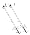
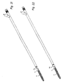
- the device comprises as main components a mantle 1, an elongated member 2, fastening elements 3 for the stent 4, control means 5 and sensing means 6.
- the length of the mantle 1 is such that the front end of the mantle 1 can reach the area of the sphincter before the prostate when the device is inserted into the male urethra via the external urethral orifice.
- the stent 4 is fastened in accordance with Fig. 2 to the first front end portion 2a of the elongated member 2.
- the outer dimensions of the tubular mantle 1 and stent 4 are selected in a manner that they can easily be brought into the male urethra.
- the control means 5 are outside the external urethra orifice when the stent 4 is installed, so that when the stent 4 is loosened for release from the device, as shown in Fig. 8, the control means 5 may be easily manipulated manually.
- the elongated member 2 shown in Figs. 6 and 7 is longer than the mantle I thereby having first and second end portions 2a, 2b protruding from the respective ends of the mantle 1.
- the first, front end portion 2a is substantially placed inside the stent 4, which in this embodiment is designed as a helical coil.
- the elongated member 2 is divided into two sections 2c, 2d, which in one embodiment of the present invention have approximately the same diameter.
- the first section 2c of the elongated member 2 has unitary construction and is formed as a stick-like element in connection with the front end portion 2a.
- the distal part of the front end portion 2a of the elongated member 2 is outside the front end of the mantle 1, which itself is divided into a second section 2d by a division of the unitary construction of the first section 2c into an outer tubular means 7a and an inner elongated means 7b, which resides inside said outer tubular means 7a.
- the outer tubular means 7a are provided with cuts, e.g., 8a, 8b in Fig. 1. Said cuts protrude from the outer tubular means 7a in the longitudinal direction. Those cuts (four of which are presented in the first embodiment of the device shown in Figs. 1-8) are equidistantly divided around the periphery of the outer tubular means 7a.
- the cuts have their distal end at the point of the division between the first and second sections, 2c and 2d.
- the proximal end of the cuts is settled at a certain distance from the front end 1a of the mantle 1, so that the stent 4 can be attached to the device as explained in more detail below.
- Means 5 for controlling the movements of the elongated member are affixed to the rear, second end portion 2b of the elongated member 2.
- the main parts of the control means 5 are a sleeve 10 and slide means 11 therein.
- the rear end part 9 of the outer tubular means 7a together with the rear end part 1 b (Fig. 6) of the mantle 1 are fixed to the front end wall 13 of the sleeve 10, and the inner elongated means 7b is fixed to the front end of the slide means 11.
- the inner elongated means 7b is arranged to go through the hole 12 in the front end wall 13 of the sleeve 10 and inside the hole 10a of the sleeve 10, wherein the slide means 11 is arranged to be moved manually in relation to the sleeve 10 in the longitudinal direction of the device.
- the sleeve 10 has at a longitudinal wall a longitudinal groove 14 which opens towards the rear end of the sleeve 10.
- the slide means 11 is provided with an elevation 15 which is positioned into the groove 14, as shown in Fig. 1.
- the slide means 11 is provided with a handle part 16 protruding from the rear end of the sleeve 10, the handle preferably including a prepared surface for manual gripping and using the control means 5.
- the stent 4 (Fig. 8), it comprises an elongated, coiled wire part 4a to be placed at the area of the prostate, a longitudinal rod part 4b connected to the elongated wire part 4a from the first end of the same and to be placed into a body cavity, such as at the area of sphincter muscle of the urethra, and further a coiled locking part 4c connected to the second end of the logitudinal rod part for placing in the urethra in front of the sphincter muscle.
- the stent 4 is preferably made of a bioabsorbable polymer material.
- the stent 4 is pushed onto the first portion 2a of the elongated member 2 in a manner that the rear end of the stent, i.e., the locking part 4c, passes the cuts, e.g., 8a, 8b, in the longitudinal direction of the elongated member 2.
- the locking part 4c is located in the area of the elongated member 2 between the cuts and the front end part 1a of the mantle 1. This phase of attaching the stent to the device is shown in Figs. 1 and 6.
- the front end 15a of the elevation 15, which has passed by the rear end 10b of the sleeve 10 is brought against said rear end 10b, thereby activating the locating means 6 at the cuts (e.g., 8a, 8b).
- This activation is due to the shortening of the distance between the front end of the second section 2d and the front end wall 13 of the sleeve 10, which is effected by pulling the inner elongated means 7b as described above.
- Such shortening causes the strips 16 (Fig.
- the locking part 4c of the stent 4 is locked between the outwardly bending strips 16 (Figs. 5 and 7) and the front end part 1a of the mantle 1, and simultaneously the strips 16, form wing-like locating means 6 just ahead of the locking part 4c projecting radially outwards from the outer surface of the device.
- the locating means 6 is used to locate the correct position of the stent 4, by preventing the locking part 4c of the stent from progressing past, e.g., the sphincter muscle.
- the slide means 11 is brought back to the position shown in Figs. 1 and 6, whereby the strips 6 are again lying in the longitudinal direction of the device, thereby releasing the locking part 4c of the stent from the locked position.
- the first position 2a of the elongated member 2 is free to be retracted from the interior of the same, as shown in Fig. 8, and further the device can be retracted from the urethra.
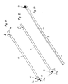
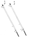
- FIG. 9-16 A second embodiment of the invention is shown in Figs. 9-16.
- the device has the same main components as the first embodiment shown in Figs. 1-8.
- the mantle 1, which in the first embodiment is constructed as a single tube is (as especially seen in Fig. 11) comprised of a locating means 6 and a ring-shaped member 17 protruding from the first end 1a of the mantle 1.
- the elongated member 2 is constructed as a single, stick-like element, as shown in Fig. 13, having a first front end portion 2a protruding from the first end 1a of the mantle 1 inside the stent 4 in a similar manner as explained in connection with the first embodiment above. With reference to Figs.
- the elongated member 2 is shown penetrating through the hole 17a of the ring-shaped member 17 when the stent 4 is locked in connection with the device.
- the first front section 2a of the elongated member 2 passes through the hole 17a of the ring-shaped member 17, forming a closed ring that locks the coiled locking part 4c of the stent 4 inside the said closed ring.
- the closed ring is opened when the the ring-shaped member 17 is released from connection to the elongated member 2. In this way, the locking part 4c and the whole stent 4 is freed from the insertion device.
- the rear end of that member is equipped with a handle and locking part 18, which is fastened frictionally to the rear end 16 of the mantle 1 when the elongated member 2 is inserted into the mantle 1 and the stent 4 is fastened to the device.
- the locating means 6 are placed at the front end of the mantle 1, as shown in Figs. 14 and 15, at a space 19 having its expansion limited by a section 20 of the surface of the mantle 1.
- the section 20 is provided with at least one aperture 21 connected by a tubular line 22 inside the mantle 1 to the second rear end 1 b of the mantle 1.
- the tubular line 22 is provided for transfer of a pressure medium to and from the space 19.
- a tubular elastic member 23, like a balloon, is overlying said section 20 of the surface of the mantle 1 and is fastened tightly from both ends of said tubular elastic member 23 onto the surface of the mantle 1, around the periphery of the same.
- An adapter 24 is fixed in connection with the mantle 1 at the rear end 1b of the same and at the rear end of the tubular line 22 for providing and releasing the pressure medium to and from the space 19.
- the second embodiment can be used in a similar manner as explained above in connection with the first embodiment of the invention.
- the balloon-like locating means 6 is expanded as shown in Fig. 15 to locate the correct position of the stent 4. After locating that correct position, the locating means 6 is deflated and the elongated member 2 is retracted, as shown in Fig. 16, whereby the stent 4 is released due to the opening of the closed ring. The device can be retracted from the urethra after the stage shown in Fig. 16.
- the locating means (balloon or cut strips or equivalent) is used to hold the stent onto the device and to localize the stent within the body cavity, thereby simplifying the device, making it easy for a surgeon to handle and reducing its risk in use during surgery. Further, unlocking the stent from the device is simple and easy, making stent placement within the body cavity more precise and exact. Indeed, only a half-turn of the tube is necessary to release the stent (or deflate the balloon), as compared to the more burdensome release techniques of the prior art, such as the device of the '374 patent (requiring several turns to release the stent).
- the outer tube of the insertion device may be made from a material that is rigid or semi-rigid, thereby facilitating stent placement, location and unlocking from the device.
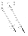
- Figs 17 and 18 show yet another embodiment of the device in which the cuts (e.g., 8A,8B) are made onto the mantle 1 at the front end of the same in a similar manner as described above.
- a cord (not shown) may be led thorough the mantle 1 in a manner that a loop is provided which locks the locking part 4c of the stent 4, and thus the whole stent, in connection with the insertion device. Both ends of the cord may be fixed to the slide means 11.
- the slide means 11 starting from the position shown in Fig 17, is pulled and turned as described above the locking part 4c forces the cuts (e.g., 8A,8B) to bend outwards to form the locating means 6A as shown in Fig 18.
- Figs 19 and 20 show yet another embodiment of the invention, comprising a combination of the embodiments of Figs 1 and 2 with that of Figs 17 and 18.
- the function of this embodiment of the device can be understood on basis of the teachings given in connection with the corresponding parts of the specification above.
- the outer tubular means 7a are provided with first cuts (e.g., 8a, 8b), said first cuts protruding from the outer tubular means 7a in the longitudinal direction of the outer tubular means 7a.
- Second cuts e.g., 8A,8B
- the first cuts (e.g., 8a,8b) lock the locking part 4c of the stent 4, thus providing a first locating means 6a as described in connection with Figs 1 and 2.
- the second cuts are bent outwards due to the continued movement of the first locating means 6a together with the locking part 4c towards the sleeve 10, thus forming the second locating means 6A.
- the first locating means 6a meets the sphincter muscle of the urethra and the stent 4 can be released as described above.
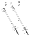
- Figs 21 and 22 show another embodiment of the invention, in which the balloon 6a fastens the stent 4 in place of the wing construction of the embodiment shown in Figs 1 and 2.
- the locating means of this embodiment are formed onto the surface of the outer tubular means 7a of the elongate member 2.
- Figs 23 and 24 show another embodiment of the invention comprising a partial combination of the embodiment of Figs 9 and 10, together with the embodiment of Figs 21 and 22.
- the first balloon 6a is formed onto the surface of the outer tubular means 7a of the elongated member 2
- the second balloon 6A is formed onto the surface of the mantle 1.
- Figs 25 and 26 depict yet another embodiment of the invention, which is a partial combination of embodiments shown in Figs 1 and 2 with that of Figs 9 and 10.
- Figs 27 and 28 show an additional embodiment of the invention, which is a partial combination of the embodiment shown in Figs 21 and 22 with that of Figs 17 and 18.
Landscapes
- Health & Medical Sciences (AREA)
- Engineering & Computer Science (AREA)
- Biomedical Technology (AREA)
- Cardiology (AREA)
- Oral & Maxillofacial Surgery (AREA)
- Transplantation (AREA)
- Heart & Thoracic Surgery (AREA)
- Vascular Medicine (AREA)
- Life Sciences & Earth Sciences (AREA)
- Animal Behavior & Ethology (AREA)
- General Health & Medical Sciences (AREA)
- Public Health (AREA)
- Veterinary Medicine (AREA)
- Media Introduction/Drainage Providing Device (AREA)
- Prostheses (AREA)
- External Artificial Organs (AREA)
- Materials For Medical Uses (AREA)
Claims (10)
- Vorrichtung zum Einsetzen eines Stents (4) in eine Körperhöhle, wobei die Vorrichtung umfasst:- Mittel (6) zum Feststellen der Position eines Hindernisses in der Körperhöhle,- einen äußeren verlängerten Mantel (1) mit einem ersten distalen Ende, das in eine Körperhöhle einzusetzen ist, und einem zweiten Ende, und- ein verlängertes Teil (2), das beweglich im Inneren des Mantels (1) angeordnet ist, wobei das verlängerte Teil (2) erste und zweite Endabschnitte (2a, 2b) besitzt, die aus den jeweiligen Enden des Mantels (1) hervorragen, wobei der erste Endabschnitt (2a) des verlängerten Teils (2) in der Lage ist, den Stent (4) in ablösbarer Weise distal von dem Mittel (6) zum Feststellen der Position eines Hindernisses entgegen zu nehmen.
- Vorrichtung nach Anspruch 1, wobei das Feststellmittel (6) radial aus dem Teil (2) oder dem Mantel (1) nach außen herausragt.
- Vorrichtung nach Anspruch 1 oder 2, wobei das Feststellmittel (6) einen Ballon umfasst, der zeitweilig aus dem Teil (2) oder dem Mantel (1) herausragen kann.
- Vorrichtung nach Anspruch 1 oder 2, wobei das Feststellmittel (6) Schnittstreifen (8a, 8b) umfasst, die zeitweilig aus dem Teil (2) oder dem Mantel (1) herausragen können.
- Vorrichtung nach Anspruch 4, wobei- der zweite Teilbereich (2b) des Teils (2) einen Außenabschnitt (7a) und einen Innenabschnitt (7b) umfasst, die jeweils erste und zweite Enden besitzen, wobei der Außenabschnitt (7a) den Innenabschnitt wenigstens teilweise umgibt, und wobei das erste Ende des Außenabschnitts (7a) und das erste Ende des Innenabschnitts (7b) mit dem ersten Teilbereich (2a) des Teils (2) in Verbindung stehen;- der Außenabschnitt (7a) einen zu ihm gehörigen Bereich mit einer Mehrzahl an dadurch verlaufenden Längsschnitten (8a, 8b) besitzt;- der Innenabschnitt (7b) des Teils (2) sich in Bezug auf den Außenabschnitt (7a) des Teils (2) in Längsrichtung bewegen kann, so dass der Außenabschnitt (7a) durch den ersten Teilbereich (2a) des Teils (2) in Längsrichtung zusammengedrückt wird, und wobei dieser Bereich des Außenabschnitts (7a) mit dadurch verlaufenden Schnitten in Bezug auf den ersten Teilbereich (2a) des Teils (2) herausragt.
- Vorrichtung nach einem der Ansprüche 1 bis 5, wobei der Stent (4) zeitweilig davon abgehalten wird, von dem Teil (2) abzurutschen.
- Vorrichtung nach einem der Ansprüche 1 bis 6, wobei der Stent (4) durch das/die Feststellmittel (6) zeitweilig davon abgehalten wird, von dem Teil (2) abzurutschen.
- Vorrichtung nach Anspruch 6, wobei vor dem Einsetzen ein Teilabschnitt des Stents (4c) an beiden Seiten des Mittels (6) zum Feststellen der Position eines Hindernisses in der Körperhöhle positioniert wird.
- Vorrichtung nach einem der Ansprüche 1 bis 6, wobei der Stent durch eine Schnur zeitweilig davon abgehalten wird, von dem Teil abzurutschen.
- Vorrichtung nach einem der Ansprüche 1 bis 6, weiterhin umfassend einen Ring (17), der am ersten Ende des Mantels (1) angebracht ist, um das Teil (2) in ablösbarer Weise entgegen zu nehmen, wobei es beim Vorschieben des Teils (2) durch einen Teil des Stents (4), durch den Ring (17) und durch einen weiteren Teil des Stents (4) so sein kann, dass sich ein Teilabschnitt des Stents (4) an beiden Seiten des Rings (17) befindet.
Applications Claiming Priority (3)
| Application Number | Priority Date | Filing Date | Title |
|---|---|---|---|
| US09/465,789 US6685734B1 (en) | 1999-12-17 | 1999-12-17 | Urethral stent delivery system |
| US465789 | 1999-12-17 | ||
| PCT/EP2000/012752 WO2001043664A1 (en) | 1999-12-17 | 2000-12-14 | Urethral stent delivery system |
Publications (2)
| Publication Number | Publication Date |
|---|---|
| EP1237505A1 EP1237505A1 (de) | 2002-09-11 |
| EP1237505B1 true EP1237505B1 (de) | 2006-03-22 |
Family
ID=23849156
Family Applications (1)
| Application Number | Title | Priority Date | Filing Date |
|---|---|---|---|
| EP00988796A Expired - Lifetime EP1237505B1 (de) | 1999-12-17 | 2000-12-14 | System zum einbringen eines harnröhrenstents |
Country Status (8)
| Country | Link |
|---|---|
| US (1) | US6685734B1 (de) |
| EP (1) | EP1237505B1 (de) |
| JP (1) | JP2003516802A (de) |
| AT (1) | ATE320775T1 (de) |
| AU (1) | AU2511301A (de) |
| DE (1) | DE60026886T2 (de) |
| ES (1) | ES2260089T3 (de) |
| WO (1) | WO2001043664A1 (de) |
Families Citing this family (20)
| Publication number | Priority date | Publication date | Assignee | Title |
|---|---|---|---|---|
| US6368346B1 (en) | 1999-06-03 | 2002-04-09 | American Medical Systems, Inc. | Bioresorbable stent |
| US8088060B2 (en) | 2000-03-15 | 2012-01-03 | Orbusneich Medical, Inc. | Progenitor endothelial cell capturing with a drug eluting implantable medical device |
| US9522217B2 (en) | 2000-03-15 | 2016-12-20 | Orbusneich Medical, Inc. | Medical device with coating for capturing genetically-altered cells and methods for using same |
| US6679909B2 (en) | 2001-07-31 | 2004-01-20 | Advanced Cardiovascular Systems, Inc. | Rapid exchange delivery system for self-expanding stent |
| US6929651B2 (en) | 2002-09-27 | 2005-08-16 | Ethicon, Inc. | Urethral catheter stent delivery system |
| US7867271B2 (en) | 2003-11-20 | 2011-01-11 | Advanced Cardiovascular Systems, Inc. | Rapid-exchange delivery systems for self-expanding stents |
| US7753906B2 (en) * | 2004-09-14 | 2010-07-13 | Richard Esposito | Catheter having anchoring and stabilizing devices |
| JP2008529597A (ja) * | 2005-02-04 | 2008-08-07 | ポリ−メッド インコーポレイティド | ファイバー強化複合材吸収性尿管内ステント |
| US8083806B2 (en) * | 2005-02-04 | 2011-12-27 | Poly-Med, Inc. | Radiation and radiochemically sterilized fiber-reinforced, composite urinogenital stents |
| US8083805B2 (en) | 2005-08-16 | 2011-12-27 | Poly-Med, Inc. | Absorbable endo-urological devices and applications therefor |
| US20070258935A1 (en) * | 2006-05-08 | 2007-11-08 | Mcentire Edward Enns | Water dispersible films for delivery of active agents to the epidermis |
| US20070259029A1 (en) * | 2006-05-08 | 2007-11-08 | Mcentire Edward Enns | Water-dispersible patch containing an active agent for dermal delivery |
| US20080057090A1 (en) * | 2006-09-01 | 2008-03-06 | Mcentire Edward Enns | Wrinkle masking film composition for skin |
| KR100780318B1 (ko) * | 2006-12-11 | 2007-11-28 | 주식회사 에스앤지바이오텍 | 인공혈관 스텐트 삽입장치 |
| US8287602B2 (en) * | 2007-12-12 | 2012-10-16 | Boston Scientific Scimed, Inc. | Urinary stent |
| US20120010645A1 (en) * | 2009-03-20 | 2012-01-12 | Proarc Medical Ltd. | Methods and devices for urethral treatment |
| WO2012123950A2 (en) | 2011-03-17 | 2012-09-20 | Proarc Medical Ltd. | Methods and devices for urethral |
| EP2809370B1 (de) * | 2012-01-30 | 2020-08-26 | Ameber Medical LTD | Negativ geladener vaskulärer stent |
| EP2967819B1 (de) | 2013-03-14 | 2021-04-28 | Proarc Medical Ltd. | Vorrichtungen zur behandlung der harnröhre |
| AU2015264609B2 (en) * | 2014-05-21 | 2017-12-07 | Boston Scientific Scimed, Inc. | Stent delivery system |
Family Cites Families (29)
| Publication number | Priority date | Publication date | Assignee | Title |
|---|---|---|---|---|
| DE2827908C2 (de) | 1975-04-12 | 1982-06-09 | Karl Dr.Med. 5300 Bonn Fabian | Katheter |
| US4531933A (en) | 1982-12-07 | 1985-07-30 | C. R. Bard, Inc. | Helical ureteral stent |
| US4512338A (en) | 1983-01-25 | 1985-04-23 | Balko Alexander B | Process for restoring patency to body vessels |
| US4790810A (en) | 1985-11-04 | 1988-12-13 | American Medical Systems, Inc. | Ureteral connector stent |
| DE3640745A1 (de) | 1985-11-30 | 1987-06-04 | Ernst Peter Prof Dr M Strecker | Katheter zum herstellen oder erweitern von verbindungen zu oder zwischen koerperhohlraeumen |
| US4820262A (en) | 1985-12-12 | 1989-04-11 | Medical Engineering Corporation | Ureteral stent |
| FR2595564A1 (fr) | 1986-03-11 | 1987-09-18 | Lavarenne Vincent | Endoprothese uretrale |
| US4713049A (en) | 1986-08-05 | 1987-12-15 | Medical Engineering Corporation | Ureteral stent kit |
| US5007898A (en) | 1988-06-02 | 1991-04-16 | Advanced Surgical Intervention, Inc. | Balloon dilatation catheter |
| US5527336A (en) | 1986-12-09 | 1996-06-18 | Boston Scientific Corporation | Flow obstruction treatment method |
| US5030227A (en) | 1988-06-02 | 1991-07-09 | Advanced Surgical Intervention, Inc. | Balloon dilation catheter |
| US4813925A (en) | 1987-04-21 | 1989-03-21 | Medical Engineering Corporation | Spiral ureteral stent |
| US4969458A (en) | 1987-07-06 | 1990-11-13 | Medtronic, Inc. | Intracoronary stent and method of simultaneous angioplasty and stent implant |
| DK163713C (da) | 1987-09-02 | 1992-09-07 | Ole Gyring Nieben | Anordning til anbringelse af et partielt kateter i et legemshulrum |
| US4820298A (en) | 1987-11-20 | 1989-04-11 | Leveen Eric G | Internal vascular prosthesis |
| US4932958A (en) | 1988-05-10 | 1990-06-12 | American Medical Systems, Inc. | Prostate balloon dilator |
| US4950227A (en) | 1988-11-07 | 1990-08-21 | Boston Scientific Corporation | Stent delivery system |
| US4973301A (en) | 1989-07-11 | 1990-11-27 | Israel Nissenkorn | Catheter and method of using same |
| US5263931A (en) | 1990-02-14 | 1993-11-23 | Advanced Cardiovascular Systems, Inc. | Balloon catheter for dilating a prostatic urethra |
| US5160341A (en) | 1990-11-08 | 1992-11-03 | Advanced Surgical Intervention, Inc. | Resorbable urethral stent and apparatus for its insertion |
| US5209725A (en) | 1991-04-11 | 1993-05-11 | Roth Robert A | Prostatic urethra dilatation catheter system and method |
| DE9114435U1 (de) | 1991-11-19 | 1992-01-16 | Engel, Konrad, Dr.med., 8178 Gaißach | Vorrichtung zur Behandlung der Harninkontinenz des Mannes |
| US5304214A (en) | 1992-01-21 | 1994-04-19 | Med Institute, Inc. | Transurethral ablation catheter |
| US5322501A (en) | 1992-10-02 | 1994-06-21 | Mahmud Durrani Ayaz | Continent urethral stent for treating and preventing urethral stricture after surgery |
| SE505436C2 (sv) | 1993-04-27 | 1997-08-25 | Ams Medinvent Sa | Prostatastent |
| IL108832A (en) * | 1994-03-03 | 1999-12-31 | Medinol Ltd | Urological stent and positioning device for it |
| US5591199A (en) | 1995-06-07 | 1997-01-07 | Porter; Christopher H. | Curable fiber composite stent and delivery system |
| FR2736554B1 (fr) | 1995-07-10 | 1997-08-29 | Devonec Marian | Catheter forme d'un moyen de catheterisation et d'un moyen d'introduction separables, utile pour le traitement des obstacles prostatiques chez l'homme |
| US5865815A (en) | 1997-04-25 | 1999-02-02 | Contimed, Inc. | Prostatic obstruction relief catheter |
-
1999
- 1999-12-17 US US09/465,789 patent/US6685734B1/en not_active Expired - Fee Related
-
2000
- 2000-12-14 EP EP00988796A patent/EP1237505B1/de not_active Expired - Lifetime
- 2000-12-14 ES ES00988796T patent/ES2260089T3/es not_active Expired - Lifetime
- 2000-12-14 AU AU25113/01A patent/AU2511301A/en not_active Abandoned
- 2000-12-14 DE DE60026886T patent/DE60026886T2/de not_active Expired - Fee Related
- 2000-12-14 WO PCT/EP2000/012752 patent/WO2001043664A1/en not_active Ceased
- 2000-12-14 AT AT00988796T patent/ATE320775T1/de not_active IP Right Cessation
- 2000-12-14 JP JP2001544606A patent/JP2003516802A/ja active Pending
Also Published As
| Publication number | Publication date |
|---|---|
| US6685734B1 (en) | 2004-02-03 |
| WO2001043664A1 (en) | 2001-06-21 |
| AU2511301A (en) | 2001-06-25 |
| DE60026886D1 (de) | 2006-05-11 |
| ES2260089T3 (es) | 2006-11-01 |
| DE60026886T2 (de) | 2007-03-15 |
| EP1237505A1 (de) | 2002-09-11 |
| JP2003516802A (ja) | 2003-05-20 |
| ATE320775T1 (de) | 2006-04-15 |
Similar Documents
| Publication | Publication Date | Title |
|---|---|---|
| EP1237505B1 (de) | System zum einbringen eines harnröhrenstents | |
| US11925376B2 (en) | Methods and devices for urethral treatment | |
| AU2020200817B2 (en) | Indwelling body lumen expander | |
| KR100276151B1 (ko) | 카테터 고정장치 | |
| US6093194A (en) | Insertion device for stents and methods for use | |
| US6162231A (en) | Stent insertion device | |
| EP2370029B1 (de) | Radiales schneideimplantat | |
| JP2011521680A (ja) | 経管腔アクセスのためのシステムおよび方法 | |
| EP1951150A1 (de) | Stent mit verankerungsteil | |
| US20120203357A1 (en) | Urethral anastomosis device | |
| US6929651B2 (en) | Urethral catheter stent delivery system | |
| US10314570B2 (en) | Surgical needle system with anchor retention features | |
| US20240023952A1 (en) | Anatomical tissue anchor and related methods | |
| CN101330877A (zh) | 用于使分别限定两个体腔的组织吻合的器械 |
Legal Events
| Date | Code | Title | Description |
|---|---|---|---|
| PUAI | Public reference made under article 153(3) epc to a published international application that has entered the european phase |
Free format text: ORIGINAL CODE: 0009012 |
|
| 17P | Request for examination filed |
Effective date: 20020705 |
|
| AK | Designated contracting states |
Kind code of ref document: A1 Designated state(s): AT BE CH CY DE DK ES FI FR GB GR IE IT LI LU MC NL PT SE TR |
|
| RAP1 | Party data changed (applicant data changed or rights of an application transferred) |
Owner name: LINVATEC BIOMATERIALS LTD. |
|
| 17Q | First examination report despatched |
Effective date: 20040116 |
|
| GRAP | Despatch of communication of intention to grant a patent |
Free format text: ORIGINAL CODE: EPIDOSNIGR1 |
|
| GRAS | Grant fee paid |
Free format text: ORIGINAL CODE: EPIDOSNIGR3 |
|
| GRAA | (expected) grant |
Free format text: ORIGINAL CODE: 0009210 |
|
| AK | Designated contracting states |
Kind code of ref document: B1 Designated state(s): AT BE CH CY DE DK ES FI FR GB GR IE IT LI LU MC NL PT SE TR |
|
| PG25 | Lapsed in a contracting state [announced via postgrant information from national office to epo] |
Ref country code: BE Free format text: LAPSE BECAUSE OF FAILURE TO SUBMIT A TRANSLATION OF THE DESCRIPTION OR TO PAY THE FEE WITHIN THE PRESCRIBED TIME-LIMIT Effective date: 20060322 Ref country code: AT Free format text: LAPSE BECAUSE OF FAILURE TO SUBMIT A TRANSLATION OF THE DESCRIPTION OR TO PAY THE FEE WITHIN THE PRESCRIBED TIME-LIMIT Effective date: 20060322 Ref country code: LI Free format text: LAPSE BECAUSE OF FAILURE TO SUBMIT A TRANSLATION OF THE DESCRIPTION OR TO PAY THE FEE WITHIN THE PRESCRIBED TIME-LIMIT Effective date: 20060322 Ref country code: NL Free format text: LAPSE BECAUSE OF FAILURE TO SUBMIT A TRANSLATION OF THE DESCRIPTION OR TO PAY THE FEE WITHIN THE PRESCRIBED TIME-LIMIT Effective date: 20060322 Ref country code: CH Free format text: LAPSE BECAUSE OF FAILURE TO SUBMIT A TRANSLATION OF THE DESCRIPTION OR TO PAY THE FEE WITHIN THE PRESCRIBED TIME-LIMIT Effective date: 20060322 |
|
| REG | Reference to a national code |
Ref country code: GB Ref legal event code: FG4D |
|
| REG | Reference to a national code |
Ref country code: CH Ref legal event code: EP |
|
| REG | Reference to a national code |
Ref country code: IE Ref legal event code: FG4D |
|
| REF | Corresponds to: |
Ref document number: 60026886 Country of ref document: DE Date of ref document: 20060511 Kind code of ref document: P |
|
| PG25 | Lapsed in a contracting state [announced via postgrant information from national office to epo] |
Ref country code: DK Free format text: LAPSE BECAUSE OF FAILURE TO SUBMIT A TRANSLATION OF THE DESCRIPTION OR TO PAY THE FEE WITHIN THE PRESCRIBED TIME-LIMIT Effective date: 20060622 Ref country code: SE Free format text: LAPSE BECAUSE OF FAILURE TO SUBMIT A TRANSLATION OF THE DESCRIPTION OR TO PAY THE FEE WITHIN THE PRESCRIBED TIME-LIMIT Effective date: 20060622 |
|
| PG25 | Lapsed in a contracting state [announced via postgrant information from national office to epo] |
Ref country code: PT Free format text: LAPSE BECAUSE OF FAILURE TO SUBMIT A TRANSLATION OF THE DESCRIPTION OR TO PAY THE FEE WITHIN THE PRESCRIBED TIME-LIMIT Effective date: 20060822 |
|
| NLV1 | Nl: lapsed or annulled due to failure to fulfill the requirements of art. 29p and 29m of the patents act | ||
| REG | Reference to a national code |
Ref country code: CH Ref legal event code: PL |
|
| ET | Fr: translation filed | ||
| REG | Reference to a national code |
Ref country code: ES Ref legal event code: FG2A Ref document number: 2260089 Country of ref document: ES Kind code of ref document: T3 |
|
| PGFP | Annual fee paid to national office [announced via postgrant information from national office to epo] |
Ref country code: GB Payment date: 20061106 Year of fee payment: 7 |
|
| PGFP | Annual fee paid to national office [announced via postgrant information from national office to epo] |
Ref country code: FI Payment date: 20061122 Year of fee payment: 7 |
|
| PGFP | Annual fee paid to national office [announced via postgrant information from national office to epo] |
Ref country code: FR Payment date: 20061201 Year of fee payment: 7 |
|
| PG25 | Lapsed in a contracting state [announced via postgrant information from national office to epo] |
Ref country code: IE Free format text: LAPSE BECAUSE OF NON-PAYMENT OF DUE FEES Effective date: 20061214 |
|
| PGFP | Annual fee paid to national office [announced via postgrant information from national office to epo] |
Ref country code: ES Payment date: 20061220 Year of fee payment: 7 |
|
| PGFP | Annual fee paid to national office [announced via postgrant information from national office to epo] |
Ref country code: DE Payment date: 20061229 Year of fee payment: 7 |
|
| PG25 | Lapsed in a contracting state [announced via postgrant information from national office to epo] |
Ref country code: MC Free format text: LAPSE BECAUSE OF NON-PAYMENT OF DUE FEES Effective date: 20061231 |
|
| PGFP | Annual fee paid to national office [announced via postgrant information from national office to epo] |
Ref country code: IT Payment date: 20061231 Year of fee payment: 7 |
|
| PLBE | No opposition filed within time limit |
Free format text: ORIGINAL CODE: 0009261 |
|
| STAA | Information on the status of an ep patent application or granted ep patent |
Free format text: STATUS: NO OPPOSITION FILED WITHIN TIME LIMIT |
|
| 26N | No opposition filed |
Effective date: 20061227 |
|
| PG25 | Lapsed in a contracting state [announced via postgrant information from national office to epo] |
Ref country code: GR Free format text: LAPSE BECAUSE OF FAILURE TO SUBMIT A TRANSLATION OF THE DESCRIPTION OR TO PAY THE FEE WITHIN THE PRESCRIBED TIME-LIMIT Effective date: 20060623 |
|
| PG25 | Lapsed in a contracting state [announced via postgrant information from national office to epo] |
Ref country code: FI Free format text: LAPSE BECAUSE OF NON-PAYMENT OF DUE FEES Effective date: 20071214 Ref country code: LU Free format text: LAPSE BECAUSE OF NON-PAYMENT OF DUE FEES Effective date: 20061214 Ref country code: TR Free format text: LAPSE BECAUSE OF FAILURE TO SUBMIT A TRANSLATION OF THE DESCRIPTION OR TO PAY THE FEE WITHIN THE PRESCRIBED TIME-LIMIT Effective date: 20060322 |
|
| GBPC | Gb: european patent ceased through non-payment of renewal fee |
Effective date: 20071214 |
|
| PG25 | Lapsed in a contracting state [announced via postgrant information from national office to epo] |
Ref country code: DE Free format text: LAPSE BECAUSE OF NON-PAYMENT OF DUE FEES Effective date: 20080701 |
|
| REG | Reference to a national code |
Ref country code: FR Ref legal event code: ST Effective date: 20081020 |
|
| PG25 | Lapsed in a contracting state [announced via postgrant information from national office to epo] |
Ref country code: CY Free format text: LAPSE BECAUSE OF FAILURE TO SUBMIT A TRANSLATION OF THE DESCRIPTION OR TO PAY THE FEE WITHIN THE PRESCRIBED TIME-LIMIT Effective date: 20060322 |
|
| PG25 | Lapsed in a contracting state [announced via postgrant information from national office to epo] |
Ref country code: GB Free format text: LAPSE BECAUSE OF NON-PAYMENT OF DUE FEES Effective date: 20071214 |
|
| REG | Reference to a national code |
Ref country code: ES Ref legal event code: FD2A Effective date: 20071215 |
|
| PG25 | Lapsed in a contracting state [announced via postgrant information from national office to epo] |
Ref country code: ES Free format text: LAPSE BECAUSE OF NON-PAYMENT OF DUE FEES Effective date: 20071215 Ref country code: FR Free format text: LAPSE BECAUSE OF NON-PAYMENT OF DUE FEES Effective date: 20071231 |
|
| PG25 | Lapsed in a contracting state [announced via postgrant information from national office to epo] |
Ref country code: IT Free format text: LAPSE BECAUSE OF NON-PAYMENT OF DUE FEES Effective date: 20071214 |