EP1237442B1 - Systeme d'ameublement pour ordinateur et procede - Google Patents
Systeme d'ameublement pour ordinateur et procede Download PDFInfo
- Publication number
- EP1237442B1 EP1237442B1 EP00983076A EP00983076A EP1237442B1 EP 1237442 B1 EP1237442 B1 EP 1237442B1 EP 00983076 A EP00983076 A EP 00983076A EP 00983076 A EP00983076 A EP 00983076A EP 1237442 B1 EP1237442 B1 EP 1237442B1
- Authority
- EP
- European Patent Office
- Prior art keywords
- display screen
- computer
- plate
- connection
- driving means
- Prior art date
- Legal status (The legal status is an assumption and is not a legal conclusion. Google has not performed a legal analysis and makes no representation as to the accuracy of the status listed.)
- Expired - Lifetime
Links
- 238000000034 method Methods 0.000 title claims abstract description 13
- 239000002023 wood Substances 0.000 claims description 3
- 230000001276 controlling effect Effects 0.000 claims description 2
- 230000001105 regulatory effect Effects 0.000 claims description 2
- 238000004804 winding Methods 0.000 claims description 2
- 230000000007 visual effect Effects 0.000 abstract description 6
- 210000002414 leg Anatomy 0.000 description 4
- 230000006378 damage Effects 0.000 description 3
- 239000002184 metal Substances 0.000 description 3
- 238000010276 construction Methods 0.000 description 2
- 238000013461 design Methods 0.000 description 2
- 239000000428 dust Substances 0.000 description 2
- 229920001821 foam rubber Polymers 0.000 description 2
- 230000002035 prolonged effect Effects 0.000 description 2
- 238000005096 rolling process Methods 0.000 description 2
- 238000007789 sealing Methods 0.000 description 2
- 208000027418 Wounds and injury Diseases 0.000 description 1
- 238000013459 approach Methods 0.000 description 1
- 230000005540 biological transmission Effects 0.000 description 1
- 238000005516 engineering process Methods 0.000 description 1
- 230000002349 favourable effect Effects 0.000 description 1
- 208000014674 injury Diseases 0.000 description 1
- 210000003127 knee Anatomy 0.000 description 1
- 230000007257 malfunction Effects 0.000 description 1
- 239000000463 material Substances 0.000 description 1
- 230000002093 peripheral effect Effects 0.000 description 1
- 239000004033 plastic Substances 0.000 description 1
- 239000007787 solid Substances 0.000 description 1
- 238000012549 training Methods 0.000 description 1
Images


Classifications
-
- A—HUMAN NECESSITIES
- A47—FURNITURE; DOMESTIC ARTICLES OR APPLIANCES; COFFEE MILLS; SPICE MILLS; SUCTION CLEANERS IN GENERAL
- A47B—TABLES; DESKS; OFFICE FURNITURE; CABINETS; DRAWERS; GENERAL DETAILS OF FURNITURE
- A47B21/00—Tables or desks for office equipment, e.g. typewriters, keyboards
- A47B21/007—Tables or desks for office equipment, e.g. typewriters, keyboards with under-desk displays, e.g. displays being viewable through a transparent working surface of the table or desk
- A47B21/0073—Tables or desks for office equipment, e.g. typewriters, keyboards with under-desk displays, e.g. displays being viewable through a transparent working surface of the table or desk liftable above the desk top
-
- A—HUMAN NECESSITIES
- A47—FURNITURE; DOMESTIC ARTICLES OR APPLIANCES; COFFEE MILLS; SPICE MILLS; SUCTION CLEANERS IN GENERAL
- A47B—TABLES; DESKS; OFFICE FURNITURE; CABINETS; DRAWERS; GENERAL DETAILS OF FURNITURE
- A47B21/00—Tables or desks for office equipment, e.g. typewriters, keyboards
- A47B21/007—Tables or desks for office equipment, e.g. typewriters, keyboards with under-desk displays, e.g. displays being viewable through a transparent working surface of the table or desk
- A47B2021/0076—Tables or desks for office equipment, e.g. typewriters, keyboards with under-desk displays, e.g. displays being viewable through a transparent working surface of the table or desk the screen being incorporated in the desk top
Definitions
- the present invention relates to a computer furniture system and a method.
- Computer furniture systems such as tables comprising a computer partly or wholly are known within the art.
- the central part of the computer itself is often built into some kind of drawer or space in which the user may operate the units of the central part by pulling out the drawer or by the fronts of the units extending from the table in such a manner that they are accessible to the user.
- This type of table has also generated several suggestions as to how the computer screen may be integrated in a reasonable way. This includes a manner which ensures that the screen is accessible to the user both when actually using the computer and when the computer is not in use.
- GB-A 2 319 467 An example of a computer furniture system is disclosed in GB-A 2 319 467.
- the document discloses an invention in which a flat display screen is positioned in a recess of a table work surface but not integrated into the table as such.
- the screen has a pivotal connection to the compartment and is positioned with the display surface upward in a storage position.
- the screen may be raised to a use position by lifting and pivoting the screen in relation to the connection.
- a commonly known approach is to build a kind of stowaway compartment under the table which extends to the upper side of the table.
- the screen is subsequently raised from a position in the stowaway compartment under the table when not in use to a position on or above the upper side of the table when in use.
- the stowaway compartment furthermore comprises a some kind of chain drive which transfers power to the plate on which the screen is often placed.
- the movement of the plate is generally controlled by some kind of rail extending in the vertical direction in the side of the stowaway compartment.
- a computer screen used together with the above-mentioned system may be based on cathode tubes or flat screen technology.
- a table with the explained screen solution has several drawbacks, one of the primary drawbacks being that the system requires a lot of space in the table itself and around/in relation to the table. Especially the stowaway compartment under the table is disadvantageous since it limits the space for the user's legs when seated at the table. Thus, the user will be locked/forced into certain sitting positions or alternatively often bump particularly his feet or knees against the stowaway compartment. As the stowaway compartment will often be made of a solid metal, this will be painful.
- the stowaway compartment will comprise one or more motors together with other electronic equipment increasing the risk of the stowaway compartment conducting quite a lot of heat to which the user's legs will be exposed. This, in turn, will result in discomfort to the user when spending long working periods at the table.
- the purpose of the invention is to create a table with a controllable screen arrangement wherein the above-mentioned problems have been eliminated.
- the purpose of the invention is to create a table which is compact and user-friendly.
- the invention relates to a computer furniture system as defined in claim 1.
- the manner in which the system is designed facilitates positioning of the system anywhere on the surface of the piece of furniture because the system does not take up a lot of space under the surface. In particular, the system will not require a lot of space in the vertical direction as is the case with some of the prior art solutions.
- the rotational movement is particularly advantageous since it does not involve a vertical lift of the display screen but only a substantially horizontal movement of the screen.
- the energy required to perform this substantially horizontal movement is significantly less than when performing a vertical lift and results in less requirements to the driving means. Due to this, the driving means may be smaller and lighter in dimension.
- the amount of heat generated by the system will be less than the amount generated by some of the prior art solutions. At the same time, the heat will be generated further away from the user's legs and the user-friendliness is hereby improved.
- the plate-like object may be a single plate similar in size to that of the computer screen or a number of smaller plates, each working as a kind of arm in connection with the display screen.
- the first connection is usually a connection pivotable around an axis in a fixed position.
- An example may be one or more separate hinges of any kind connecting the plate-like object with the surface.
- an integrated hinge in the plate-like object and/or in the surface is also possible.
- the second connection is usually a connection pivotable around an axis where the axis may be moved within a space.
- An example may also be one or more separate hinges of any kind connecting the plate-like object with the display screen.
- an integrated hinge in the plate-like object and/or in the display screen is also possible.
- said at least one plate-like object is made of wood, it is possible to establish visual cooperation with the surface of the furniture.
- the plate-like object may be made of plastic or metal as mentioned above.
- said at least one plate-like object is substantially identical in size with that of the display screen, it is possible to perform an almost symmetrical movement.
- said furniture comprises one or more driving means, it is possible to control the movement of the display screen in a preferred manner.
- the possibility of adjusting the stop position of the screen is particularly advantageous since the angle of the screen can be controlled which ensures a favourable position in relation to the user.
- said driving means includes at least one electric motor, it is possible to adjust the angle of the display screen in a stepless fashion.
- the driving means may be a DC motor, a linear motor, pneumatic or hydraulic pump means or any other form of power-driven means.
- the movement of the display screen by driving means may be in only one direction i.e. from the storage position to the in-use position. The movement of the display screen in the opposite direction may be achieved by the user moving it to its storage position.
- said furniture comprises sliding means, it is possible to control the movement of the display screen in a preferable manner in which the friction coefficient is minimised.
- said sliding means comprises at least two rails, it is possible to guide the slide off the display screen in a preferred manner.
- angle of the rotation from a storage position to an in-use position is between 60 and 180 degrees, and preferably between 75 and 120 degrees, it is possible to achieve a preferred embodiment of the invention.
- said driving means follows a pre-established moment curve, it is possible to ensure that the display screen and the plate-like object perform the desired movement.
- the moment curve may be different from that of the end of a movement and the actual performance may be measured.
- the life of the system is also prolonged due to the fact that the different parts of the system are protected against dust and other kinds of dirt.
- the system includes computer means electrically connected to said display screen and where said computer means are placed in one or more compartments in the piece of furniture, it is possible to create a compact piece of computer furniture in which the computer can be totally concealed.
- a visual display unit for a piece of furniture comprising at least one plate-like object, at least one display screen where said plate-like object comprises a connection to said display screen, and where said display screen is capable of performing a rotational movement with the centre of rotation being in said connection from a storage position to an in-use position and vice versa, it is possible to create a compact and user-friendly unit.
- the visual display unit may be used as a computer screen in a computer system. It is, however, also possible to use the system in connection with e.g. information systems or television systems. Another field of application may be in relation to a teaching system where a number of visual display units may be connected to a central computer operated by the teacher. Yet another field of application may be in relation to an information system with a visual display unit such as libraries, public offices or similar places where the possibility of placing the display screen in a protected storage position when not in use is particularly advantageous.
- the invention also relates to a method of transferring a display screen from a substantially horizontal position in which it is partly or completely concealed in a compartment of a piece of furniture by being substantially faced down into a position in which it can be viewed by a user of the display screen or vice versa
- the piece of furniture includes a surface defining a plane and drive means such as power driving means, where said display screen is rotated around an axis defined by a second connection between the display screen and at least one plate-like object from the substantially horizontal position to the position in which it can be viewed or vice versa, said plate-like object pivots around an axis defining a first connection between said object and said furniture and a part of said display screen opposite said second connection performs a sliding movement in relation to said surface plane by said drive means.
- the rotational movement is particularly advantageous since it does not involve a vertical lift of the display screen but only a substantially horizontal movement of the screen.
- the energy required to perform this substantially horizontal movement is significantly less than when performing a vertical lift and results in less requirements to the driving means. Due to this, the driving means may be smaller and lighter in dimension.
- the amount of heat generated by the system will be less than the amount generated by some of the prior art solutions. At the same time, the heat will be generated further away from the users legs and the user-friendliness is hereby improved.
- the part of the display screen in question will usually and preferably be the base of the display screen. However, the part in question may also be on the sides of the display screen and usually in the lower part of the screen.
- the rails may curve downwards in the part close to the storage position and upwards against the in-use position. In this situation, it will be easy to move the display screen from the storage position because of gravitation. Similarly, the return to the storage position will also be smoother because of the uphill movement.
- the life of the system is also prolonged due to the fact that the different parts of the system are protected against dust and other kinds of dirt.
- One part of the rolling/un-rolling operation may involve a spring to move the curtain or to assist in the movement of the curtain.
- Especially the direct connection of the display screen to the toothed belt is advantageous over an indirect connection e.g. through a number of wheels.
- the movement in a horizontal direction is advantageous due to the reduced energy requirements when performing the movement.
- the invention relates to a display screen arrangement for a computer system, said system being incorporated in a piece of furniture such as a desk or a similar piece of furniture and said screen arrangement also being partly incorporated therein.
- Fig. 1 shows a preferred embodiment of the invention where the furniture is a desk 10.
- the desk has a writing surface 11 and a number of drawers 14 where the drawers 14 may contain a different parts of a computer system such as a central unit and computer read and write units, i.e. CD-ROM and diskette drives.
- the desk further comprises a drawer or compartment 15 for one or more computer input devices such as a keyboard and a computer mouse.
- peripheral equipment such as printers, plotters etc., may also be placed in the drawer or compartment 15.
- the computer system has an electrical connection to a display screen 12 placed on the surface of the desk.
- the display screen 12 is mechanically connected to a plate-like object 13 which is mechanically connected to the surface 11.
- the display screen 12 is preferably a flat screen and the plate-like object 13 is a wooden plate similar in size to that of the flat screen.
- Fig. 2 shows the desk from fig. 1 seen from above in storage position. It is seen that the plate-like object closes tightly around the surface of the desk.
- the surface has a groove and a sealing ring beneath the object which enhances the tightness even further.
- Fig. 3 shows the computer furniture system with a display screen 12 and a plate-like object 13 in different positions seen from the side.
- a person using the display screen is positioned to the left of the display screen and has to look to his right to see the display screen.
- the line 20 illustrates sliding means such as rails wherein the display screen may slide from a storage position (marked A) to an in-use position (marked E).
- the front side of the display screen 12 is substantially facing downwards and follows the angle of the sliding means 20.
- the plate-like object 13 is levelled with the surface 11 of the desk 10.
- the driving means has pushed the display screen 12 and the plate-like object 13 up from the surface but the screen is still substantially facing downwards and the angle between the display screen 12 and the plate-like object 13 is quite small.
- the driving means has pushed the display screen 12 and the plate-like object 13 further up from the surface and the screen no longer faces downwards but has become increasingly vertical.
- the angle between the display screen 12 and the plate-like object 13 has become wider.
- the display screen 12 In a fifth position (marked E), the display screen 12 is in an in-use position where the front of the display screen faces the person using the display screen.
- the plate-like object 13 is holding and supporting the display screen 12 in an in-use position.
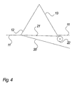
- Fig. 4 shows the computer furniture system where the display screen 12 and the plate-like object 13 is in an in-use position as described above.
- the system further has a curtain 21 and a curtain holder 22, the curtain being connected to the display screen at the base of the screen.
- the display screen 12 When moving from storage position to an in-use position, the display screen 12 will draw out the curtain 21 from the curtain holder 22.
- Fig. 5 shows a preferred embodiment of the driving means to the computer furniture system.
- the driving means includes an electric motor 31 which is connected with a first driving shaft 38
- the first driving shaft 38 is connected with a second adjustable shaft 39 by a toothed belt 41.
- the power from the driving shaft 38 is transmitted via a first toothed belt wheel 42 to the toothed belt 41 and via a second toothed belt wheel 43 to the second shaft where the wheels 42, 43 are mounted on the driving shaft 38 and the second shaft 39, respectively.
- the toothed belt 41 is connected to an arm with pivotable connection braces 45 capable of holding the display screen since the ends of the display screen arm are mounted slideably into two rails 33, 34 on each side.
- the rails 33, 34 further have means for holding the other shafts in fixed positions including the shaft in the curtain holder 47.
- the curtain 46 has means for connecting the curtain directly or indirectly with the display screen 12 where the indirect connection may be to the toothed belt 41 right behind the display screen.
- the driving means further includes a shaft 40 to keep the toothed belt 41 tight together with front 35 and back frames 36.
- the front frame includes a foam rubber list 37 to ensure that the display screen 12 is not damaged when returning it to storage position A.
- the front frame and the back frame, the rails on the right and left sides and the bottom plate define an interior compartment of the piece of furniture.
- the plate-like object In the storage position of the display screen, the plate-like object will close the compartment at the top and in the in-use position, the curtain will have the same function.
- the functionality of the driving means is as follows:
- the motor 31 rotates the first driving shaft which is aided by the second shaft and drives the toothed belt forward.
- the display screen 12 mounted on an arm 44 will also move forward from its storage position A because the arm is connected to the toothed belt 41.
- the display screen 12 will also move upwards due to the connection to the plate-like object 13, said object having a further connection to the area of the back frame 36.
- the plate-like object defines a fixed distance at which the top of the display screen is connected to the plate-like object.
- the display screen 12 will move towards the back frame 36 and the screen will return to storage position A. In this position, the display screen 12 will be substantially horizontal with the front facing downwards and the plate-like object 13 on top of it.
- the display screen 12 may be moved by one toothed belt 41 or a number of belts such as two belts placed at each side of the system to ensure symmetric transmission of power to the display screen 12.
- the movement of the display screen 12 is controlled by end stops positioned at each end of the rails 33, 34.
- the end stops preferably control a switch mounted in the power lines which connects or disconnects power to the electric motor.
- the end stops or similar switches in the path of the display screen may be used to control the on/off function of the display screen and/or the rest of a computer system. In a similar way, it will be possible to control the position of the display screen by turning the computer system on or off, i.e. the display screen will move to an in-use position when the computer is turned on and to a storage position when it is turned off.
- toothed wheels or a rack and pinion drive may replace the toothed belt.
Landscapes
- Devices For Indicating Variable Information By Combining Individual Elements (AREA)
- Digital Computer Display Output (AREA)
- Bipolar Transistors (AREA)
- Multi Processors (AREA)
Claims (20)
- Système d'ameublement pour ordinateur comprenant une surface (11) définissant un plan horizontal, ledit système comprenant:dans lequel ledit objet ayant la forme d'une plaque (13) comprend une première connexion (16) avec ladite surface (11) au niveau de l'une de ses extrémités, et une deuxième connexion (17) avec ledit écran d'affichage (12) au niveau de l'autre de ses extrémités;au moins un objet ayant la forme d'une plaque (13);au moins un écran d'affichage (12);un ou plusieurs moyens d'entraínement, comme des moyens d'entraínement électriques par exemple;
dans lequel ladite première connexion (16) peut pivoter autour d'un axe par rapport au dit plan de surface (11);
dans lequel ledit écran d'affichage (12) peut exécuter un mouvement de rotation par rapport au dit objet ayant la forme d'une plaque (13) le centre de rotation se situant au niveau de ladite deuxième connexion (17), et moyennant quoi ledit écran d'affichage (12) tourne depuis une position de rangement (A) jusqu'à une position d'utilisation (E); et caractérisé en ce que:une partie dudit écran d'affichage (12) opposée à ladite deuxième connexion (17) comprend des moyens de coulissement (20), dans lesquels ledit écran d'affichage (12) exécute un mouvement de coulissement par rapport au dit plan de surface, entraíné par lesdits moyens d'entraínement;et ledit écran d'affichage (12) est sensiblement dirigé face vers le bas dans ladite position de rangement. - Système d'ameublement pour ordinateur selon la revendication 1, dans lequel ledit écran d'affichage (12) est un écran plat.
- Système d'ameublement pour ordinateur selon la revendication 1, dans lequel ledit au moins un objet ayant la forme d'une plaque (13) est en bois.
- Système d'ameublement pour ordinateur selon la revendication 1, dans lequel ledit au moins un objet ayant la forme d'une plaque (13) a des dimensions sensiblement semblables à celles dudit écran d'affichage.
- Système d'ameublement pour ordinateur selon la revendication 1, dans lequel lesdits moyens d'entraínement comprennent au moins un moteur électrique (31).
- Système d'ameublement pour ordinateur selon la revendication 1, dans lequel lesdits moyens de coulissement comprennent au moins deux rails (33, 34) agencés en relation avec ledit plan de surface.
- Système d'ameublement pour ordinateur selon la revendication 1, dans lequel l'angle de rotation depuis ladite position de rangement (A) jusqu'à ladite position d'utilisation (E) est compris entre 60 et 180 degrés et, de préférence, entre 75 et 120 degrés.
- Système d'ameublement pour ordinateur selon la revendication 1, dans lequel ladite position de rangement (A) et ladite position d'utilisation (E) sont délimitées par des butées d'extrémité qui contrôlent lesdits moyens d'entraínement.
- Système d'ameublement pour ordinateur selon la revendication 1, dans lequel lesdits moyens d'entraínement suivent une courbe de moment pré établie.
- Système d'ameublement pour ordinateur selon la revendication 1, dans lequel ledit écran d'affichage (12) est relié à un rideau (21, 46) et à un dispositif de support de rideau (22,47).
- Système d'ameublement pour ordinateur selon la revendication 1, dans lequel le système comprend des moyens d'ordinateur reliés par des moyens électriques audit écran d'affichage, et dans lequel lesdits moyens d'ordinateur sont placés dans un ou plusieurs compartiment(s) de l'élément d'ameublement.
- Procédé permettant de faire passer un écran d'affichage (12) d'une position sensiblement horizontale dans laquelle il est partiellement ou complètement enfermé dans un compartiment d'un élément d'ameublement en étant sensiblement dirigé face vers le bas, jusqu'à une position dans laquelle il peut être vu par un utilisateur de l'écran l'affichage, ou vice versa, par lequel l'élément d'ameublement comprend une surface (11) définissant un plan horizontal et des moyens d'entraínement comme des moyens d'entraínement électriques par exemple; dans lequel
ledit écran d'affichage (12) tourne autour d'un axe défini par une deuxième connexion (17) entre l'écran l'affichage (12) et au moins un objet ayant la forme d'une plaque (13), depuis la position sensiblement horizontale jusqu'à la position dans laquelle il peut être vu, ou vice versa;
ledit objet ayant la forme d'une plaque (13) pivote autour d'un axe définissant une première connexion (16) entre ledit objet ayant la forme d'une plaque et ledit ameublement;
et
une partie dudit écran d'affichage (12) opposée à ladite deuxième connexion (17) exécute un mouvement de coulissement par rapport audit plan de surface (11), par lesdits moyens d'entraínement. - Procédé selon la revendication 12, par lequel ledit écran tourne à un angle compris entre 60 et 180 degrés et, de préférence, entre 75 et 120 degrés.
- Procédé selon la revendication 12 ou 13, par lequel ladite partie dudit écran d'affichage est reliée à des moyens de rideau déplacés au cours de ladite rotation dudit écran d'affichage.
- Procédé selon la revendication 14, par lequel ledit mouvement est exécuté sous la forme d'une opération d'enroulement / de déroulement.
- Procédé selon la revendication 14, par lequel ledit mouvement est exécuté sous la forme d'une opération d'étirement desdits moyens de rideau.
- Procédé selon l'une quelconque des revendications 12 à 16, par lequel une partie dudit écran d'affichage est reliée à une courroie dentée qui déplace ladite partie dans une direction sensiblement horizontale.
- Procédé selon la revendication 17, par lequel ladite courroie dentée est entraínée par un moteur électrique.
- Procédé selon la revendication 18, par lequel le courant qui alimente ledit moteur est régulé et/ou contrôlé pendant lesdits mouvements.
- Procédé selon la revendication 19, par lequel ledit courant est réduit lorsque ledit écran d'affichage est proche d'un point d'extrémité de son mouvement.
Applications Claiming Priority (3)
| Application Number | Priority Date | Filing Date | Title |
|---|---|---|---|
| DK199900442U DK199900442U3 (da) | 1999-12-13 | 1999-12-13 | Integreret pc/skrivebord |
| DK44299 | 1999-12-13 | ||
| PCT/DK2000/000691 WO2001043590A1 (fr) | 1999-12-13 | 2000-12-13 | Systeme d'ameublement pour ordinateur, terminal de visualisation pour mobilier, procede et utilisation associes |
Publications (2)
| Publication Number | Publication Date |
|---|---|
| EP1237442A1 EP1237442A1 (fr) | 2002-09-11 |
| EP1237442B1 true EP1237442B1 (fr) | 2004-09-22 |
Family
ID=8157143
Family Applications (1)
| Application Number | Title | Priority Date | Filing Date |
|---|---|---|---|
| EP00983076A Expired - Lifetime EP1237442B1 (fr) | 1999-12-13 | 2000-12-13 | Systeme d'ameublement pour ordinateur et procede |
Country Status (6)
| Country | Link |
|---|---|
| EP (1) | EP1237442B1 (fr) |
| AT (1) | ATE276686T1 (fr) |
| AU (1) | AU1995901A (fr) |
| DE (1) | DE60014153D1 (fr) |
| DK (1) | DK199900442U3 (fr) |
| WO (1) | WO2001043590A1 (fr) |
Families Citing this family (4)
| Publication number | Priority date | Publication date | Assignee | Title |
|---|---|---|---|---|
| GB0215053D0 (en) | 2002-06-28 | 2002-08-07 | Therefore Ltd | A console |
| EP1691645A4 (fr) * | 2003-11-25 | 2007-08-01 | Herma Technologies Pty Ltd | Appareil de dissimulation d'un produit |
| DE202005005586U1 (de) * | 2005-04-07 | 2005-06-02 | P.A.U.L. GmbH Pädagogische Ausstattungs- und Lernsysteme | Arbeitstisch für unterschiedliche Verwendungszwecke |
| GB2425722B (en) * | 2005-05-05 | 2009-06-24 | Stephen King | Display storage device |
Family Cites Families (7)
| Publication number | Priority date | Publication date | Assignee | Title |
|---|---|---|---|---|
| DE277878C (fr) * | 1913-08-21 | 1914-09-10 | ||
| GB191512167A (en) * | 1915-08-24 | 1915-10-21 | John Alexander Baines | Improvements in and relating to Book Rests. |
| US4440373A (en) * | 1981-02-17 | 1984-04-03 | Bruce Beitler | Folio and notebook display stand |
| US4562482A (en) * | 1983-07-29 | 1985-12-31 | Brown Robert L | Computerized executive work station |
| US5452950A (en) * | 1994-04-15 | 1995-09-26 | Crenshaw; Ralph E. | Desk-station, computerized school desk |
| US5526756A (en) * | 1995-01-12 | 1996-06-18 | Watson; David J. | Adjustable computer desk |
| GB9619697D0 (en) * | 1996-09-20 | 1996-11-06 | Powerdesk Plc | Displays |
-
1999
- 1999-12-13 DK DK199900442U patent/DK199900442U3/da active
-
2000
- 2000-12-13 WO PCT/DK2000/000691 patent/WO2001043590A1/fr not_active Ceased
- 2000-12-13 AU AU19959/01A patent/AU1995901A/en not_active Abandoned
- 2000-12-13 EP EP00983076A patent/EP1237442B1/fr not_active Expired - Lifetime
- 2000-12-13 DE DE60014153T patent/DE60014153D1/de not_active Expired - Lifetime
- 2000-12-13 AT AT00983076T patent/ATE276686T1/de not_active IP Right Cessation
Also Published As
| Publication number | Publication date |
|---|---|
| AU1995901A (en) | 2001-06-25 |
| ATE276686T1 (de) | 2004-10-15 |
| DE60014153D1 (de) | 2004-10-28 |
| DK199900442U3 (da) | 2000-02-11 |
| EP1237442A1 (fr) | 2002-09-11 |
| WO2001043590A1 (fr) | 2001-06-21 |
Similar Documents
| Publication | Publication Date | Title |
|---|---|---|
| US20050275322A1 (en) | Wheelchair accommodating system | |
| US8893628B2 (en) | Dispatch desk with focal length adjustability | |
| US11395544B1 (en) | Keyboard tray that adjusts horizontally and vertically | |
| US5088421A (en) | Adjustable height desk | |
| JP3207307U (ja) | 昇降式折り畳みデスク | |
| CN102869287B (zh) | 端正姿势用书桌和包括该书桌的系统家具 | |
| US5450800A (en) | Ergonomically adjustable computer workstation | |
| US7677518B2 (en) | Adjustable stand for monitor and keyboard | |
| US12114780B2 (en) | Single-motor electrically powered bed | |
| US7721658B2 (en) | Computer workstation with movable monitor support | |
| WO2023004413A2 (fr) | Système d'exercice à poids libres | |
| US20090062072A1 (en) | Mid-deck hinged foldable treadmill deck | |
| US20120248263A1 (en) | Computer work desk | |
| US10842693B2 (en) | Motorized mount for seating system | |
| US20210093494A1 (en) | Motorized mount for seating system | |
| WO2002054910A1 (fr) | Pupitre et poste de travail informatise | |
| EP1237442B1 (fr) | Systeme d'ameublement pour ordinateur et procede | |
| KR200491564Y1 (ko) | 음악 전문가용 책상 | |
| KR101667758B1 (ko) | 교육용 책상 모니터 각도 조절장치 | |
| CN111329265A (zh) | 一种多功能折叠收纳电脑桌 | |
| US20140268560A1 (en) | Motorized mount for seating system | |
| EP4609755A1 (fr) | Bureau intelligent | |
| CN219049270U (zh) | 按摩床设备 | |
| KR200404849Y1 (ko) | 승강식 교탁 | |
| CN222516400U (zh) | 一种带有调节功能的读书台 |
Legal Events
| Date | Code | Title | Description |
|---|---|---|---|
| PUAI | Public reference made under article 153(3) epc to a published international application that has entered the european phase |
Free format text: ORIGINAL CODE: 0009012 |
|
| 17P | Request for examination filed |
Effective date: 20020607 |
|
| AK | Designated contracting states |
Kind code of ref document: A1 Designated state(s): AT BE CH CY DE DK ES FI FR GB GR IE IT LI LU MC NL PT SE TR |
|
| AX | Request for extension of the european patent |
Free format text: AL;LT;LV;MK;RO;SI |
|
| 17Q | First examination report despatched |
Effective date: 20030620 |
|
| GRAP | Despatch of communication of intention to grant a patent |
Free format text: ORIGINAL CODE: EPIDOSNIGR1 |
|
| RTI1 | Title (correction) |
Free format text: COMPUTER FURNITURE SYSTEM AND A METHOD |
|
| GRAS | Grant fee paid |
Free format text: ORIGINAL CODE: EPIDOSNIGR3 |
|
| GRAA | (expected) grant |
Free format text: ORIGINAL CODE: 0009210 |
|
| AK | Designated contracting states |
Kind code of ref document: B1 Designated state(s): AT BE CH CY DE DK ES FI FR GB GR IE IT LI LU MC NL PT SE TR |
|
| PG25 | Lapsed in a contracting state [announced via postgrant information from national office to epo] |
Ref country code: IT Free format text: LAPSE BECAUSE OF FAILURE TO SUBMIT A TRANSLATION OF THE DESCRIPTION OR TO PAY THE FEE WITHIN THE PRESCRIBED TIME-LIMIT;WARNING: LAPSES OF ITALIAN PATENTS WITH EFFECTIVE DATE BEFORE 2007 MAY HAVE OCCURRED AT ANY TIME BEFORE 2007. THE CORRECT EFFECTIVE DATE MAY BE DIFFERENT FROM THE ONE RECORDED. Effective date: 20040922 Ref country code: FI Free format text: LAPSE BECAUSE OF FAILURE TO SUBMIT A TRANSLATION OF THE DESCRIPTION OR TO PAY THE FEE WITHIN THE PRESCRIBED TIME-LIMIT Effective date: 20040922 Ref country code: FR Free format text: LAPSE BECAUSE OF FAILURE TO SUBMIT A TRANSLATION OF THE DESCRIPTION OR TO PAY THE FEE WITHIN THE PRESCRIBED TIME-LIMIT Effective date: 20040922 Ref country code: AT Free format text: LAPSE BECAUSE OF FAILURE TO SUBMIT A TRANSLATION OF THE DESCRIPTION OR TO PAY THE FEE WITHIN THE PRESCRIBED TIME-LIMIT Effective date: 20040922 Ref country code: CY Free format text: LAPSE BECAUSE OF FAILURE TO SUBMIT A TRANSLATION OF THE DESCRIPTION OR TO PAY THE FEE WITHIN THE PRESCRIBED TIME-LIMIT Effective date: 20040922 Ref country code: LI Free format text: LAPSE BECAUSE OF FAILURE TO SUBMIT A TRANSLATION OF THE DESCRIPTION OR TO PAY THE FEE WITHIN THE PRESCRIBED TIME-LIMIT Effective date: 20040922 Ref country code: TR Free format text: LAPSE BECAUSE OF FAILURE TO SUBMIT A TRANSLATION OF THE DESCRIPTION OR TO PAY THE FEE WITHIN THE PRESCRIBED TIME-LIMIT Effective date: 20040922 Ref country code: CH Free format text: LAPSE BECAUSE OF FAILURE TO SUBMIT A TRANSLATION OF THE DESCRIPTION OR TO PAY THE FEE WITHIN THE PRESCRIBED TIME-LIMIT Effective date: 20040922 Ref country code: BE Free format text: LAPSE BECAUSE OF FAILURE TO SUBMIT A TRANSLATION OF THE DESCRIPTION OR TO PAY THE FEE WITHIN THE PRESCRIBED TIME-LIMIT Effective date: 20040922 Ref country code: NL Free format text: LAPSE BECAUSE OF FAILURE TO SUBMIT A TRANSLATION OF THE DESCRIPTION OR TO PAY THE FEE WITHIN THE PRESCRIBED TIME-LIMIT Effective date: 20040922 |
|
| REG | Reference to a national code |
Ref country code: GB Ref legal event code: FG4D |
|
| REG | Reference to a national code |
Ref country code: CH Ref legal event code: EP |
|
| REG | Reference to a national code |
Ref country code: IE Ref legal event code: FG4D |
|
| REF | Corresponds to: |
Ref document number: 60014153 Country of ref document: DE Date of ref document: 20041028 Kind code of ref document: P |
|
| PG25 | Lapsed in a contracting state [announced via postgrant information from national office to epo] |
Ref country code: IE Free format text: LAPSE BECAUSE OF NON-PAYMENT OF DUE FEES Effective date: 20041213 Ref country code: LU Free format text: LAPSE BECAUSE OF NON-PAYMENT OF DUE FEES Effective date: 20041213 |
|
| PG25 | Lapsed in a contracting state [announced via postgrant information from national office to epo] |
Ref country code: GR Free format text: LAPSE BECAUSE OF FAILURE TO SUBMIT A TRANSLATION OF THE DESCRIPTION OR TO PAY THE FEE WITHIN THE PRESCRIBED TIME-LIMIT Effective date: 20041222 Ref country code: DK Free format text: LAPSE BECAUSE OF FAILURE TO SUBMIT A TRANSLATION OF THE DESCRIPTION OR TO PAY THE FEE WITHIN THE PRESCRIBED TIME-LIMIT Effective date: 20041222 Ref country code: SE Free format text: LAPSE BECAUSE OF FAILURE TO SUBMIT A TRANSLATION OF THE DESCRIPTION OR TO PAY THE FEE WITHIN THE PRESCRIBED TIME-LIMIT Effective date: 20041222 |
|
| PG25 | Lapsed in a contracting state [announced via postgrant information from national office to epo] |
Ref country code: DE Free format text: LAPSE BECAUSE OF FAILURE TO SUBMIT A TRANSLATION OF THE DESCRIPTION OR TO PAY THE FEE WITHIN THE PRESCRIBED TIME-LIMIT Effective date: 20041223 |
|
| PG25 | Lapsed in a contracting state [announced via postgrant information from national office to epo] |
Ref country code: MC Free format text: LAPSE BECAUSE OF NON-PAYMENT OF DUE FEES Effective date: 20041231 |
|
| PG25 | Lapsed in a contracting state [announced via postgrant information from national office to epo] |
Ref country code: ES Free format text: LAPSE BECAUSE OF FAILURE TO SUBMIT A TRANSLATION OF THE DESCRIPTION OR TO PAY THE FEE WITHIN THE PRESCRIBED TIME-LIMIT Effective date: 20050102 |
|
| LTIE | Lt: invalidation of european patent or patent extension |
Effective date: 20040922 |
|
| REG | Reference to a national code |
Ref country code: CH Ref legal event code: PL |
|
| NLV1 | Nl: lapsed or annulled due to failure to fulfill the requirements of art. 29p and 29m of the patents act | ||
| PLBE | No opposition filed within time limit |
Free format text: ORIGINAL CODE: 0009261 |
|
| STAA | Information on the status of an ep patent application or granted ep patent |
Free format text: STATUS: NO OPPOSITION FILED WITHIN TIME LIMIT |
|
| 26N | No opposition filed |
Effective date: 20050623 |
|
| REG | Reference to a national code |
Ref country code: IE Ref legal event code: MM4A |
|
| EN | Fr: translation not filed | ||
| PG25 | Lapsed in a contracting state [announced via postgrant information from national office to epo] |
Ref country code: PT Free format text: LAPSE BECAUSE OF NON-PAYMENT OF DUE FEES Effective date: 20050222 |
|
| PGFP | Annual fee paid to national office [announced via postgrant information from national office to epo] |
Ref country code: GB Payment date: 20081118 Year of fee payment: 9 |
|
| GBPC | Gb: european patent ceased through non-payment of renewal fee |
Effective date: 20091213 |
|
| PG25 | Lapsed in a contracting state [announced via postgrant information from national office to epo] |
Ref country code: GB Free format text: LAPSE BECAUSE OF NON-PAYMENT OF DUE FEES Effective date: 20091213 |