EP1237361A2 - Dispositif pour la réduction du bruit dans des signaux d'images - Google Patents
Dispositif pour la réduction du bruit dans des signaux d'images Download PDFInfo
- Publication number
- EP1237361A2 EP1237361A2 EP02100198A EP02100198A EP1237361A2 EP 1237361 A2 EP1237361 A2 EP 1237361A2 EP 02100198 A EP02100198 A EP 02100198A EP 02100198 A EP02100198 A EP 02100198A EP 1237361 A2 EP1237361 A2 EP 1237361A2
- Authority
- EP
- European Patent Office
- Prior art keywords
- spectral component
- filter
- frequency spectral
- signal
- low
- Prior art date
- Legal status (The legal status is an assumption and is not a legal conclusion. Google has not performed a legal analysis and makes no representation as to the accuracy of the status listed.)
- Withdrawn
Links
- 230000003595 spectral effect Effects 0.000 claims abstract description 44
- 230000003111 delayed effect Effects 0.000 claims abstract description 9
- 230000002123 temporal effect Effects 0.000 claims description 21
- 239000003638 chemical reducing agent Substances 0.000 description 8
- 238000000034 method Methods 0.000 description 4
- 238000011161 development Methods 0.000 description 2
- 238000010586 diagram Methods 0.000 description 2
- 230000006870 function Effects 0.000 description 2
- 230000010354 integration Effects 0.000 description 2
- 238000012935 Averaging Methods 0.000 description 1
- 208000010201 Exanthema Diseases 0.000 description 1
- 230000015572 biosynthetic process Effects 0.000 description 1
- 230000001419 dependent effect Effects 0.000 description 1
- 230000000694 effects Effects 0.000 description 1
- 201000005884 exanthem Diseases 0.000 description 1
- 238000012545 processing Methods 0.000 description 1
- 206010037844 rash Diseases 0.000 description 1
- 230000004044 response Effects 0.000 description 1
- 238000012549 training Methods 0.000 description 1
Images

Classifications
-
- H—ELECTRICITY
- H04—ELECTRIC COMMUNICATION TECHNIQUE
- H04N—PICTORIAL COMMUNICATION, e.g. TELEVISION
- H04N5/00—Details of television systems
- H04N5/14—Picture signal circuitry for video frequency region
- H04N5/21—Circuitry for suppressing or minimising disturbance, e.g. moiré or halo
Definitions
- the invention relates to a device for noise reduction in image signals.
- Devices with temporal recursive filters are used to reduce noise in image signals known, for example by DE 27 50 173 C2.
- the feedback factor is dependent on the known devices controlled by movement in the image. The movement is through the formation of the amount the differences in the image signals of two successive images determined.
- the task is therefore to specify a device for reducing noise in image signals, which also reduces noise with existing movements without disturbing artifacts get into the image signals.
- This object is achieved in that the image signals in at least a locally low-frequency spectral component and a locally higher-frequency spectral component be split that the higher frequency spectral component over a temporal filter is passed and that the output signal of the temporal filter and the corresponding delayed low-frequency spectral component added to a noise-reduced image signal become.
- the device according to the invention has the advantage that even in moving image areas Noise reduction is achieved without the need for complex motion estimation procedures and motion compensation must be used. Furthermore, the The device according to the invention is very robust against film flicker interference, since this occur only in the low-pass channel. In the known method for noise reduction namely generate the low-frequency film flicker interference in the motion detector of the noise reducer a significant rash, which leads to a response of the Motion detector leads and thus a noise reduction even with still pictures prevented or severely restricted.
- the device according to the invention offers the possibility of the effect of noise reduction to be limited to the maximum expected local extent of the disturbance. For example, since the film grain of a 35mm negative film is much finer than that of a copied Super 16mm film, the aperture of the FIR filter (size of the Filter window) during signal splitting can be reduced accordingly. This leads to even fewer object replicas in the higher frequency spectral component and reduced the risk of artifacts, such as tracing or ghosting of moving Objects.
- the higher-frequency spectral component can existing movements are preferably evaluated in that the temporal Filter is a recursive filter, the feedback factor of which is from a motion detector is controllable, to which the higher-frequency spectral component can be supplied.
- the temporal Filter is a recursive filter, the feedback factor of which is from a motion detector is controllable, to which the higher-frequency spectral component can be supplied.
- temporal filters such as temporal transversal and median filters, can also be used.
- An advantageous embodiment of the invention is that to derive the low-frequency Spectral component a local low-pass filter of the size of about 5x5 to 11x11 Image elements is provided and that for deriving the higher-frequency spectral component a subtraction of the low-frequency spectral component from that corresponding to the filter runtime delayed image signal occurs.
- This configuration has the advantage that that which is disruptive when playing color films Grain falls in the higher-frequency spectral component and is therefore subjected to noise reduction
- An FIR filter can preferably be used as the local low-pass filter become.
- the invention is also with a two-dimensional (horizontal / vertical) Median filter can be sensed.
- a different treatment is also different with the device according to the invention
- Coarse noise structures (grain structures) possible, for which in a further training it is provided that an average spectral component of the image signal is also derived and that the average spectral component is passed through another temporal filter and that the output signal of the further temporal filter to the delayed low-frequency Spectral component and added to the output signal of the temporal filter.
- This further development is preferably designed such that the further temporal filter is another recursive filter, the feedback factor of another motion detector is controllable, the middle spectral portion can be felt.
- the reduction at a predetermined value of a movement signal representing the movement and with a larger movement signal drops to a minimum.
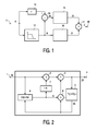
- the known noise reducer 2 explains how it is used in the exemplary embodiments.
- the higher-frequency spectral component Xh is supplied via an input 1. He arrives via a multiplier 2 and an adder 3 as a component Zh to the output 4. Zh fed to an image memory 5 and delayed by one image period from the image memory read out as signal Yh.
- the signal Yh is the second multiplier 6 Adder 3 supplied.
- the multiplier 6 is the feedback factor K and the Multiplier 2 supplied via a circuit 7 a factor 1-K.
- the feedback factor K is derived in the case of the noise reducer according to FIG. 2 by that at 8 the amount of the difference between the respectively supplied signal Xh and the Signal Yh is formed.
- the image signal X is input 11 a local low-pass filter 12 and a delay element 13 are supplied.
- the low pass filter 12 is preferably an FIR filter and detects, for example, five successive ones Picture elements in five lines.
- the low-frequency spectral component Xl and that image signal X correspondingly delayed at 13 are subtracted at 14, so that the higher frequency Spectral component Xh arises from a noise reducer 15, which is shown schematically in Fig. 2 is shown, is supplied.
- a delay device in the branch for the low-frequency spectral components X1 16 arranged. Instead of this delay device, however, signal processing circuits can also be used are inserted, which are only on the low-frequency Should affect spectral component, for example a circuit arrangement for reduction of low-frequency flickering.
- the spectral components Zh and Zl are then at 17 added and can be taken from an output 18 as a noise-reduced image signal Z. become.
- the higher-frequency spectral components Xh contain the complete interference component (noise) as well as the fine picture details.
- noise reduction method which is based on the complete image signal acts, for example, on the front and rear edges of the moving objects large difference signals (X-Y), so that the feedback factor K is practically zero, which in the sense of hindering movement movement is positive, but does not mean reduced noise in these image areas.
- 3 is a further low-pass filter 21 with a higher cut-off frequency than the low-pass filter 12 provided with a further subtraction circuit 22, so that a total of spectral components Xh, Xm and Xl arise.
- a separate noise reducer 23 is provided, which is similar that is constructed according to FIG. 2.
- the adder circuit 24 then has three Inputs.
- the signal Z can be taken from the output 25.
- the filter window and, if appropriate, can be selected by setting the noise reducers 16, 23 the character of the noise reduction as a whole customized requirements. For example, in one of the Spectral ranges h or m a stronger noise reduction than in the other to create a certain artistic impression - for example so-called cinema feeling.
- Fig. 4 shows an embodiment in which the noise-reduced higher frequency Spectral component is fed to the adder 17 via a multiplier 31.
- the multiplier is controlled by a factor M, which is the higher frequency spectral component attenuates when the motion detector of the recursive filter has a predetermined value, which is above the noise threshold.
- the noise reducer 15 the difference signal
- the factor M is below the given value for movement Value 1 and then, for example with a hyperbolic function, takes a value of 0.5 with strong movement.
Landscapes
- Engineering & Computer Science (AREA)
- Multimedia (AREA)
- Signal Processing (AREA)
- Picture Signal Circuits (AREA)
- Image Processing (AREA)
Applications Claiming Priority (2)
| Application Number | Priority Date | Filing Date | Title |
|---|---|---|---|
| DE10109968 | 2001-03-01 | ||
| DE10109968A DE10109968A1 (de) | 2001-03-01 | 2001-03-01 | Einrichtung zur Rauschreduktion in Bildsignalen |
Publications (1)
| Publication Number | Publication Date |
|---|---|
| EP1237361A2 true EP1237361A2 (fr) | 2002-09-04 |
Family
ID=7675996
Family Applications (1)
| Application Number | Title | Priority Date | Filing Date |
|---|---|---|---|
| EP02100198A Withdrawn EP1237361A2 (fr) | 2001-03-01 | 2002-02-28 | Dispositif pour la réduction du bruit dans des signaux d'images |
Country Status (4)
| Country | Link |
|---|---|
| US (1) | US20020122139A1 (fr) |
| EP (1) | EP1237361A2 (fr) |
| JP (1) | JP2002344773A (fr) |
| DE (1) | DE10109968A1 (fr) |
Cited By (1)
| Publication number | Priority date | Publication date | Assignee | Title |
|---|---|---|---|---|
| CN116269467A (zh) * | 2023-05-19 | 2023-06-23 | 中国人民解放军总医院第八医学中心 | 一种创伤患者清创术前信息采集系统 |
Families Citing this family (3)
| Publication number | Priority date | Publication date | Assignee | Title |
|---|---|---|---|---|
| JP4534121B2 (ja) * | 2003-12-10 | 2010-09-01 | ソニー株式会社 | ノイズ除去装置、ノイズ除去方法およびノイズ除去プログラム |
| US8184705B2 (en) | 2008-06-25 | 2012-05-22 | Aptina Imaging Corporation | Method and apparatus for motion compensated filtering of video signals |
| JP5235807B2 (ja) * | 2009-07-23 | 2013-07-10 | 三菱電機株式会社 | ノイズ除去装置 |
Family Cites Families (6)
| Publication number | Priority date | Publication date | Assignee | Title |
|---|---|---|---|---|
| FR2507041B1 (fr) * | 1981-05-27 | 1985-10-18 | Thomson Csf | Dispositif correcteur d'un signal videofrequence de television par attenuation dynamique du niveau du bruit et source d'images de television comportant un tel dispositif |
| US4827528A (en) * | 1985-11-15 | 1989-05-02 | Stanford University | Error-minimizing noise-reduction system |
| DE4239396C1 (de) * | 1992-11-24 | 1994-02-24 | Itt Ind Gmbh Deutsche | Verfahren zur Erzeugung eines modifizierten Videosignals |
| DE4319342C2 (de) * | 1993-06-11 | 1999-05-20 | Philips Patentverwaltung | Verfahren zur Reduktion von Störungen |
| JPH11503594A (ja) * | 1996-02-05 | 1999-03-26 | フィリップス エレクトロニクス ネムローゼ フェンノートシャップ | 画像データノイズフィルタ処理 |
| KR100344807B1 (ko) * | 2000-01-12 | 2002-07-20 | 엘지전자주식회사 | 영상 신호 보정 장치 및 방법 |
-
2001
- 2001-03-01 DE DE10109968A patent/DE10109968A1/de not_active Withdrawn
-
2002
- 2002-02-26 US US10/084,840 patent/US20020122139A1/en not_active Abandoned
- 2002-02-28 EP EP02100198A patent/EP1237361A2/fr not_active Withdrawn
- 2002-02-28 JP JP2002053951A patent/JP2002344773A/ja active Pending
Cited By (2)
| Publication number | Priority date | Publication date | Assignee | Title |
|---|---|---|---|---|
| CN116269467A (zh) * | 2023-05-19 | 2023-06-23 | 中国人民解放军总医院第八医学中心 | 一种创伤患者清创术前信息采集系统 |
| CN116269467B (zh) * | 2023-05-19 | 2023-07-28 | 中国人民解放军总医院第八医学中心 | 一种创伤患者清创术前信息采集系统 |
Also Published As
| Publication number | Publication date |
|---|---|
| DE10109968A1 (de) | 2002-09-12 |
| US20020122139A1 (en) | 2002-09-05 |
| JP2002344773A (ja) | 2002-11-29 |
Similar Documents
| Publication | Publication Date | Title |
|---|---|---|
| DE69028946T2 (de) | Verfahren zur adaptiven Schärfung elektronischer Bilder | |
| DE60026925T2 (de) | Einstellung des Kontrasts eines Digitalbildes mit einem adaptiven, rekursiven Filter | |
| DE69604670T2 (de) | Bildverbesserung | |
| DE69812800T2 (de) | Verfahren und Gerät zur Bildverbesserung | |
| DE3121597C3 (de) | System zur Verminderung des Rauschens in einem Fernseh-Bildsignal | |
| DE3307687C3 (de) | System zur Verminderung des Rauschens in einem Fernsehsignal | |
| DE69611113T2 (de) | Vorrichtung zur Videorauschreduktion | |
| DE4319342C2 (de) | Verfahren zur Reduktion von Störungen | |
| DE4417628C1 (de) | Verfahren zur adaptiven Rauschverminderung für digitale Bildsequenzen | |
| DE69332107T2 (de) | Gerät und Verfahren zur Bewegungskompensierung in Bildsequenzen | |
| DE602004012125T2 (de) | Robuste rekursive hüllenoperatoren für die schnelle verarbeitung von bildern des retinex-typs | |
| DE69032548T2 (de) | Korrelationsberechnungseinrichtung | |
| DE102016121755A1 (de) | Verfahren zum Bestimmen eines zusammengesetzten Bilds eines Umgebungsbereichs eines Kraftfahrzeugs mit Anpassung von Helligkeit und/oder Farbe, Kamerasystem sowie Krafzfahrzeug | |
| DE69419768T2 (de) | Bildreduktions-vergrösserungsvorrichtungen und verfahren zum generieren von niedrigfrequenz-gefilterten bildern | |
| DE69624213T2 (de) | Bildrauschverringerungssystem | |
| EP1237361A2 (fr) | Dispositif pour la réduction du bruit dans des signaux d'images | |
| DE1462775B2 (de) | Schaltungsanordnung zur vertikalen aperturkorrektur eines fernsehsignals | |
| DE4031785A1 (de) | Verfahren zur reduktion von rauschen in videosignalen | |
| DE69320194T2 (de) | Filterarchitektur, besonders für Videoanwendungen | |
| DE19639355A1 (de) | Verfahren und Anordnung zum Farbstanzen | |
| DE3309715C2 (fr) | ||
| DE3150008C2 (fr) | ||
| DE69512008T2 (de) | Vorrichtung und Gerät zum Hervorheben der Umrisse in einen Videobild | |
| DE69423449T2 (de) | Vorrichtung zur Rauschverminderung | |
| DE19713177C2 (de) | Verfahren und Schaltungsanordnung zur Rauschreduktion bei Fernseh- oder Videosignalen |
Legal Events
| Date | Code | Title | Description |
|---|---|---|---|
| PUAI | Public reference made under article 153(3) epc to a published international application that has entered the european phase |
Free format text: ORIGINAL CODE: 0009012 |
|
| AK | Designated contracting states |
Kind code of ref document: A2 Designated state(s): AT BE CH CY DE DK ES FI FR GB GR IE IT LI LU MC NL PT SE TR |
|
| AX | Request for extension of the european patent |
Free format text: AL;LT;LV;MK;RO;SI |
|
| RAP1 | Party data changed (applicant data changed or rights of an application transferred) |
Owner name: PHILIPS CORPORATE INTELLECTUAL PROPERTY GMBH Owner name: KONINKLIJKE PHILIPS ELECTRONICS N.V. |
|
| RAP1 | Party data changed (applicant data changed or rights of an application transferred) |
Owner name: PHILIPS INTELLECTUAL PROPERTY & STANDARDS GMBH Owner name: KONINKLIJKE PHILIPS ELECTRONICS N.V. |
|
| STAA | Information on the status of an ep patent application or granted ep patent |
Free format text: STATUS: THE APPLICATION HAS BEEN WITHDRAWN |
|
| 18W | Application withdrawn |
Effective date: 20031229 |