EP1237361A2 - Device for reducing noise in picture signals - Google Patents
Device for reducing noise in picture signals Download PDFInfo
- Publication number
- EP1237361A2 EP1237361A2 EP02100198A EP02100198A EP1237361A2 EP 1237361 A2 EP1237361 A2 EP 1237361A2 EP 02100198 A EP02100198 A EP 02100198A EP 02100198 A EP02100198 A EP 02100198A EP 1237361 A2 EP1237361 A2 EP 1237361A2
- Authority
- EP
- European Patent Office
- Prior art keywords
- spectral component
- filter
- frequency spectral
- signal
- low
- Prior art date
- Legal status (The legal status is an assumption and is not a legal conclusion. Google has not performed a legal analysis and makes no representation as to the accuracy of the status listed.)
- Withdrawn
Links
- 230000003595 spectral effect Effects 0.000 claims abstract description 44
- 230000003111 delayed effect Effects 0.000 claims abstract description 9
- 230000002123 temporal effect Effects 0.000 claims description 21
- 239000003638 chemical reducing agent Substances 0.000 description 8
- 238000000034 method Methods 0.000 description 4
- 238000011161 development Methods 0.000 description 2
- 238000010586 diagram Methods 0.000 description 2
- 230000006870 function Effects 0.000 description 2
- 230000010354 integration Effects 0.000 description 2
- 238000012935 Averaging Methods 0.000 description 1
- 208000010201 Exanthema Diseases 0.000 description 1
- 230000015572 biosynthetic process Effects 0.000 description 1
- 230000001419 dependent effect Effects 0.000 description 1
- 230000000694 effects Effects 0.000 description 1
- 201000005884 exanthem Diseases 0.000 description 1
- 238000012545 processing Methods 0.000 description 1
- 206010037844 rash Diseases 0.000 description 1
- 230000004044 response Effects 0.000 description 1
- 238000012549 training Methods 0.000 description 1
Images

Classifications
-
- H—ELECTRICITY
- H04—ELECTRIC COMMUNICATION TECHNIQUE
- H04N—PICTORIAL COMMUNICATION, e.g. TELEVISION
- H04N5/00—Details of television systems
- H04N5/14—Picture signal circuitry for video frequency region
- H04N5/21—Circuitry for suppressing or minimising disturbance, e.g. moiré or halo
Definitions
- the invention relates to a device for noise reduction in image signals.
- Devices with temporal recursive filters are used to reduce noise in image signals known, for example by DE 27 50 173 C2.
- the feedback factor is dependent on the known devices controlled by movement in the image. The movement is through the formation of the amount the differences in the image signals of two successive images determined.
- the task is therefore to specify a device for reducing noise in image signals, which also reduces noise with existing movements without disturbing artifacts get into the image signals.
- This object is achieved in that the image signals in at least a locally low-frequency spectral component and a locally higher-frequency spectral component be split that the higher frequency spectral component over a temporal filter is passed and that the output signal of the temporal filter and the corresponding delayed low-frequency spectral component added to a noise-reduced image signal become.
- the device according to the invention has the advantage that even in moving image areas Noise reduction is achieved without the need for complex motion estimation procedures and motion compensation must be used. Furthermore, the The device according to the invention is very robust against film flicker interference, since this occur only in the low-pass channel. In the known method for noise reduction namely generate the low-frequency film flicker interference in the motion detector of the noise reducer a significant rash, which leads to a response of the Motion detector leads and thus a noise reduction even with still pictures prevented or severely restricted.
- the device according to the invention offers the possibility of the effect of noise reduction to be limited to the maximum expected local extent of the disturbance. For example, since the film grain of a 35mm negative film is much finer than that of a copied Super 16mm film, the aperture of the FIR filter (size of the Filter window) during signal splitting can be reduced accordingly. This leads to even fewer object replicas in the higher frequency spectral component and reduced the risk of artifacts, such as tracing or ghosting of moving Objects.
- the higher-frequency spectral component can existing movements are preferably evaluated in that the temporal Filter is a recursive filter, the feedback factor of which is from a motion detector is controllable, to which the higher-frequency spectral component can be supplied.
- the temporal Filter is a recursive filter, the feedback factor of which is from a motion detector is controllable, to which the higher-frequency spectral component can be supplied.
- temporal filters such as temporal transversal and median filters, can also be used.
- An advantageous embodiment of the invention is that to derive the low-frequency Spectral component a local low-pass filter of the size of about 5x5 to 11x11 Image elements is provided and that for deriving the higher-frequency spectral component a subtraction of the low-frequency spectral component from that corresponding to the filter runtime delayed image signal occurs.
- This configuration has the advantage that that which is disruptive when playing color films Grain falls in the higher-frequency spectral component and is therefore subjected to noise reduction
- An FIR filter can preferably be used as the local low-pass filter become.
- the invention is also with a two-dimensional (horizontal / vertical) Median filter can be sensed.
- a different treatment is also different with the device according to the invention
- Coarse noise structures (grain structures) possible, for which in a further training it is provided that an average spectral component of the image signal is also derived and that the average spectral component is passed through another temporal filter and that the output signal of the further temporal filter to the delayed low-frequency Spectral component and added to the output signal of the temporal filter.
- This further development is preferably designed such that the further temporal filter is another recursive filter, the feedback factor of another motion detector is controllable, the middle spectral portion can be felt.
- the reduction at a predetermined value of a movement signal representing the movement and with a larger movement signal drops to a minimum.
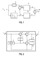
- the known noise reducer 2 explains how it is used in the exemplary embodiments.
- the higher-frequency spectral component Xh is supplied via an input 1. He arrives via a multiplier 2 and an adder 3 as a component Zh to the output 4. Zh fed to an image memory 5 and delayed by one image period from the image memory read out as signal Yh.
- the signal Yh is the second multiplier 6 Adder 3 supplied.
- the multiplier 6 is the feedback factor K and the Multiplier 2 supplied via a circuit 7 a factor 1-K.
- the feedback factor K is derived in the case of the noise reducer according to FIG. 2 by that at 8 the amount of the difference between the respectively supplied signal Xh and the Signal Yh is formed.
- the image signal X is input 11 a local low-pass filter 12 and a delay element 13 are supplied.
- the low pass filter 12 is preferably an FIR filter and detects, for example, five successive ones Picture elements in five lines.
- the low-frequency spectral component Xl and that image signal X correspondingly delayed at 13 are subtracted at 14, so that the higher frequency Spectral component Xh arises from a noise reducer 15, which is shown schematically in Fig. 2 is shown, is supplied.
- a delay device in the branch for the low-frequency spectral components X1 16 arranged. Instead of this delay device, however, signal processing circuits can also be used are inserted, which are only on the low-frequency Should affect spectral component, for example a circuit arrangement for reduction of low-frequency flickering.
- the spectral components Zh and Zl are then at 17 added and can be taken from an output 18 as a noise-reduced image signal Z. become.
- the higher-frequency spectral components Xh contain the complete interference component (noise) as well as the fine picture details.
- noise reduction method which is based on the complete image signal acts, for example, on the front and rear edges of the moving objects large difference signals (X-Y), so that the feedback factor K is practically zero, which in the sense of hindering movement movement is positive, but does not mean reduced noise in these image areas.
- 3 is a further low-pass filter 21 with a higher cut-off frequency than the low-pass filter 12 provided with a further subtraction circuit 22, so that a total of spectral components Xh, Xm and Xl arise.
- a separate noise reducer 23 is provided, which is similar that is constructed according to FIG. 2.
- the adder circuit 24 then has three Inputs.
- the signal Z can be taken from the output 25.
- the filter window and, if appropriate, can be selected by setting the noise reducers 16, 23 the character of the noise reduction as a whole customized requirements. For example, in one of the Spectral ranges h or m a stronger noise reduction than in the other to create a certain artistic impression - for example so-called cinema feeling.
- Fig. 4 shows an embodiment in which the noise-reduced higher frequency Spectral component is fed to the adder 17 via a multiplier 31.
- the multiplier is controlled by a factor M, which is the higher frequency spectral component attenuates when the motion detector of the recursive filter has a predetermined value, which is above the noise threshold.
- the noise reducer 15 the difference signal
- the factor M is below the given value for movement Value 1 and then, for example with a hyperbolic function, takes a value of 0.5 with strong movement.
Abstract
Description
Die Erfindung betrifft eine Einrichtung zur Rauschreduktion in Bildsignalen.The invention relates to a device for noise reduction in image signals.
Zur Rauschreduktion in Bildsignalen sind Einrichtungen mit zeitlichen Rekursivfiltern bekannt, beispielsweise durch DE 27 50 173 C2. Je höher dabei der Rückkopplungsfaktor ist, je besser ist die Rauschreduktion, weil dann letztendlich der Bildinhalt vieler Bilder gemittelt wird Bei bewegten Bildinhalten ist jedoch eine Integration von Bild zu Bild nur in Grenzen möglich, da ansonsten eine Unschärfe der bewegten Bildinhalte auftritt. Deshalb wird bei den bekannten Einrichtungen der Rückkopplungsfaktor in Abhängigkeit von einer Bewegung im Bild gesteuert. Die Bewegung wird durch die Bildung des Betrags der Differenzen der Bildsignale zweier aufeinanderfolgender Bilder ermittelt.Devices with temporal recursive filters are used to reduce noise in image signals known, for example by DE 27 50 173 C2. The higher the feedback factor is, the better the noise reduction is, because then ultimately the image content of many images is averaged With moving picture content, however, integration is only from picture to picture possible within limits, otherwise blurring of the moving image content occurs. Therefore, the feedback factor is dependent on the known devices controlled by movement in the image. The movement is through the formation of the amount the differences in the image signals of two successive images determined.
Bei den bekannten Verfahren geht man letztendlich davon aus, dass das Rauschen bei bewegten Bildinhalten nicht so störend wie bei ruhenden Bildinhalten ist. Dies ist insbesondere jedoch bei der Bewegung von großen flächigen Objekten nicht unbedingt der Fall.In the known methods, it is ultimately assumed that the noise is moving picture content is not as annoying as with still picture content. This is particularly so however, this is not necessarily the case when moving large flat objects Case.
Aufgabe ist es daher, eine Einrichtung zur Rauschreduktion in Bildsignalen anzugeben, welche auch bei vorliegenden Bewegungen eine Rauschreduktion vornimmt, ohne dass störende Artefakte in die Bildsignale geraten.The task is therefore to specify a device for reducing noise in image signals, which also reduces noise with existing movements without disturbing artifacts get into the image signals.
Diese Aufgabe wird erfindungsgemäß dadurch gelöst, dass die Bildsignale in mindestens einen örtlich niederfrequenten Spektralanteil und einen örtlich höherfrequenten Spektralanteil aufgespalten werden, dass der höherfrequente Spektralanteil über ein zeitliches Filter geleitet wird und dass das Ausgangssignal des zeitlichen Filters und der entsprechend verzögerte niederfrequente Spektralanteil zu einem rauschreduzierten Bildsignal addiert werden. This object is achieved in that the image signals in at least a locally low-frequency spectral component and a locally higher-frequency spectral component be split that the higher frequency spectral component over a temporal filter is passed and that the output signal of the temporal filter and the corresponding delayed low-frequency spectral component added to a noise-reduced image signal become.
Die erfindungsgemäße Einrichtung hat den Vorteil, dass auch in bewegten Bildbereichen eine Rauschreduktion erzielt wird, ohne dass aufwendige Verfahren zur Bewegungsschätzung und Bewegungskompensation eingesetzt werden müssen. Ferner ist die erfindungsgemäße Einrichtung sehr robust gegenüber Film-Flacker-Störungen, da diese ausschließlich im Tiefpasskanal auftreten. Bei dem bekannten Verfahren zur Rauschreduktion erzeugen nämlich die niederfrequenten Film-Flacker-Störungen im Bewegungsdetektor des Rauschreduzierers einen erheblichen Ausschlag, was zu einem Ansprechen des Bewegungsdetektors führt und somit eine Rauschreduktion selbst bei unbewegten Bildern verhindert oder stark einschränkt.The device according to the invention has the advantage that even in moving image areas Noise reduction is achieved without the need for complex motion estimation procedures and motion compensation must be used. Furthermore, the The device according to the invention is very robust against film flicker interference, since this occur only in the low-pass channel. In the known method for noise reduction namely generate the low-frequency film flicker interference in the motion detector of the noise reducer a significant rash, which leads to a response of the Motion detector leads and thus a noise reduction even with still pictures prevented or severely restricted.
Die erfindungsgemäße Einrichtung bietet die Möglichkeit, die Wirkung der Rauschreduktion auf eine maximal zu erwartende örtliche Ausdehnung der Störung zu begrenzen. Da beispielsweise das Filmkorn eines 35mm-Negativfilms wesentlich feiner ist als bei einem umkopierten Super-16mm-Film, kann die Apertur des FIR-Filters (Größe des Filterfensters) bei der Signalaufspaltung entsprechend verkleinert werden. Dies führt zu noch weniger Objekt-Nachbildungen im höherfrequenten Spektralanteil und verringert die Gefahr von Artefakten, wie beispielsweise Nachziehen oder Geisterbilder von bewegten Objekten.The device according to the invention offers the possibility of the effect of noise reduction to be limited to the maximum expected local extent of the disturbance. For example, since the film grain of a 35mm negative film is much finer than that of a copied Super 16mm film, the aperture of the FIR filter (size of the Filter window) during signal splitting can be reduced accordingly. this leads to even fewer object replicas in the higher frequency spectral component and reduced the risk of artifacts, such as tracing or ghosting of moving Objects.
Auch bei der erfindungsgemäßen Einrichtung können in dem höherfrequenten Spektralanteil vorliegende Bewegungen vorzugsweise dadurch ausgewertet werden, dass das zeitliche Filter ein Rekursivfilter ist, dessen Rückkopplungsfaktor von einem Bewegungsdetektor steuerbar ist, dem der höherfrequente Spektralanteil zuführbar ist. Es sind jedoch auch andere zeitliche Filter, wie zeitliche Transversal- und Medianfilter, anwendbar.Even with the device according to the invention, the higher-frequency spectral component can existing movements are preferably evaluated in that the temporal Filter is a recursive filter, the feedback factor of which is from a motion detector is controllable, to which the higher-frequency spectral component can be supplied. However, there are other temporal filters, such as temporal transversal and median filters, can also be used.
Eine vorteilhafte Ausgestaltung der Erfindung besteht darin, dass zur Ableitung des niederfrequenten Spektralanteils ein örtliches Tiefpassfilter der Größe von etwa 5x5 bis 11x11 Bildelementen vorgesehen ist und dass zur Ableitung des höherfrequenten Spektralanteils eine Subtraktion des niederfrequenten Spektralanteils von dem entsprechend der Filterlaufzeit verzögerten Bildsignal erfolgt. An advantageous embodiment of the invention is that to derive the low-frequency Spectral component a local low-pass filter of the size of about 5x5 to 11x11 Image elements is provided and that for deriving the higher-frequency spectral component a subtraction of the low-frequency spectral component from that corresponding to the filter runtime delayed image signal occurs.
Diese Ausgestaltung hat den Vorteil, dass das bei der Wiedergabe von Farbfilmen störende Korn in den höherfrequenten Spektralanteil fällt und somit der Rauschreduktion unterworfen wird Als örtliches Tiefpassfilter kann vorzugsweise ein FIR-Filter verwendet werden. Die Erfindung ist jedoch auch mit einem zweidimensionalen (horizontal/vertikal) Medianfilter durchfühlbar.This configuration has the advantage that that which is disruptive when playing color films Grain falls in the higher-frequency spectral component and is therefore subjected to noise reduction An FIR filter can preferably be used as the local low-pass filter become. However, the invention is also with a two-dimensional (horizontal / vertical) Median filter can be sensed.
Mit der erfindungsgemäßen Einrichtung ist auch eine unterschiedliche Behandlung verschieden grober Rauschstrukturen (Kornstrukturen) möglich, wozu bei einer Weiterbildung vorgesehen ist, dass ferner ein mittlerer Spektralanteil des Bildsignals abgeleitet wird und dass der mittlere Spektralanteil über ein weiteres zeitliches Filter geleitet wird und dass das Ausgangssignal des weiteren zeitlichen Filters zum verzögerten niederfrequenten Spektralanteil und zum Ausgangssignal des zeitlichen Filters hinzuaddiert wird.A different treatment is also different with the device according to the invention Coarse noise structures (grain structures) possible, for which in a further training it is provided that an average spectral component of the image signal is also derived and that the average spectral component is passed through another temporal filter and that the output signal of the further temporal filter to the delayed low-frequency Spectral component and added to the output signal of the temporal filter.
Diese Weiterbildung wird vorzugsweise derart ausgestaltet, dass das weitere zeitliche Filter ein weiteres Rekursivfilter ist, dessen Rückkopplungsfaktor von einem weiteren Bewegungsdetektor steuerbar ist, dem der mittlere Spektralanteil zufühlbar ist.This further development is preferably designed such that the further temporal filter is another recursive filter, the feedback factor of another motion detector is controllable, the middle spectral portion can be felt.
Da bei der Aufnahme von Filmen eine Integration des einfallenden Lichtes über jeweils eine Bildperiode stattfindet, werden die Kanten von bewegenden Objekten entsprechend unscharf verschliffen. Da in diesen Bildbereichen dann praktisch keine hohen Spektralanteile des Nutzsignals auftreten, kann mit einer anderen Weiterbildung der Erfindung das Rauschen in diesen Bildbereichen dadurch weiter reduziert werden, dass das Ausgangssignal des zeitlichen Filters und/oder das Ausgangssignal des weiteren zeitlichen Filters mit einem Bewegungssignal derart steuerbar ist, dass die Amplitude des Ausgangssignals mit zunehmender Bewegung verringert wird.Because when recording films, an integration of the incident light over each an image period takes place, the edges of moving objects are corresponding blurred out of focus. Since there are practically no high spectral components in these image areas of the useful signal can occur with another development of the invention Noise in these image areas can be further reduced by having the output signal of the temporal filter and / or the output signal of the further temporal filter with a motion signal can be controlled such that the amplitude of the output signal with increasing movement is reduced.
Dabei ist vorzugsweise vorgesehen, dass die Verringerung bei einem vorgegebenen Wert eines die Bewegung darstellenden Bewegungssignals einsetzt und bei größerem Bewegungssignal auf einen Mindestwert abfällt. It is preferably provided that the reduction at a predetermined value of a movement signal representing the movement and with a larger movement signal drops to a minimum.
Ausführungsbeispiele der Erfindung sind in der Zeichnung anhand mehrerer Figuren jeweils als Blockschaltbild dargestellt und in der nachfolgenden Beschreibung näher erläutert. Es zeigt:
- Fig. 1
- ein erstes Ausführungsbeispiel,
- Fig. 2
- einen bekannten Rauschreduzierer zur Verwendung bei der erfindungsgemäßen Einrichtung,
- Fig. 3
- ein zweites Ausführungsbeispiel und
- Fig. 4
- ein drittes Ausführungsbeispiel.
- Fig. 1
- a first embodiment,
- Fig. 2
- a known noise reducer for use in the device according to the invention,
- Fig. 3
- a second embodiment and
- Fig. 4
- a third embodiment.
Die Darstellung als Blockschaltbild besagt nicht, dass die einzelnen Funktionen tatsächlich in einzelnen Schaltungen durchgeführt werden. Es ist vielmehr die Anwendung von programmierbaren Prozessoren zur Durchführung der Berechnungen möglich und vorteilhaft.The representation as a block diagram does not mean that the individual functions actually be carried out in individual circuits. Rather, it is the application of programmable ones Processors for performing the calculations possible and advantageous.
Vor der Erklärung der einzelnen Ausführungsbeispiele wird der an sich bekannte Rauschreduzierer
nach Fig. 2 erläutert, wie er in den Ausführungsbeispielen angewendet wird.Before the explanation of the individual exemplary embodiments, the
Über einen Eingang 1 wird der höherfrequente Spektralanteil Xh zugeführt. Er gelangt
über einen Multiplizierer 2 und einen Addierer 3 als Anteil Zh zum Ausgang 4. Zh wird
einem Bildspeicher 5 zugeleitet und um eine Bildperiode verzögert aus dem Bildspeicher
als Signal Yh ausgelesen. Das Signal Yh wird über einen zweiten Multiplizierer 6 dem
Addierer 3 zugeführt. Dem Multiplizierer 6 wird der Rückkopplungsfaktor K und dem
Multiplizierer 2 über eine Schaltung 7 ein Faktor 1-K zugeführt.The higher-frequency spectral component Xh is supplied via an
Insoweit enthält die Einrichtung nach Fig. 2 ein bekanntes Rekursivfilter. Ist K=0, wird Xh
unverändert zum Ausgang 4 weitergeleitet. Es findet bei K=0 keine Rauschreduktion statt.
Mit größer werdendem K, wird auch der Anteil des aus dem Bildspeicher 5 ausgelesenen
Signals Yh am Ausgangssignal Zh größer. Bei K=1 wird nur noch das gespeicherte Signal
Yh ausgelesen und wieder eingeschrieben. Aus Stabilitätsgründen wird der Maximalwert
von K etwas unter 1 gehalten. Es findet dann eine Mittelwertbildung aufeinanderfolgender
Bilder im Bildspeicher 5 statt, so dass statistische Störungen (Rauschen) reduziert werden.To this extent, the device according to FIG. 2 contains a known recursive filter. If K = 0, Xh
forwarded unchanged to output 4. No noise reduction takes place at K = 0.
As the K increases, the proportion of that read from the
Der Rückkopplungsfaktor K wird bei dem Rauschreduzierer nach Fig. 2 dadurch abgeleitet, dass bei 8 der Betrag der Differenz des jeweils zugeführten Signals Xh und des Signals Yh gebildet wird.The feedback factor K is derived in the case of the noise reducer according to FIG. 2 by that at 8 the amount of the difference between the respectively supplied signal Xh and the Signal Yh is formed.
Bei dem Ausführungsbeispiel nach Fig. 1 wird das Bildsignal X von einem Eingang 11
einem örtlichen Tiefpassfilter 12 und einem Verzögerungsglied 13 zugeführt. Das Tiefpassfilter
12 ist vorzugsweise ein FIR-Filter und erfasst beispielsweise fünf aufeinanderfolgende
Bildelemente in fünf Zeilen. Der niederfrequente Spektralanteil Xl und das
entsprechend bei 13 verzögerte Bildsignal X werden bei 14 subtrahiert, so dass der höherfrequente
Spektralanteil Xh entsteht, der einem Rauschreduzierer 15, der schematisch in
Fig. 2 dargestellt ist, zugeführt wird.1, the image signal X is input 11
a local low-
In dem Zweig für die niederfrequenten Spektralanteile Xl ist eine Verzögerungseinrichtung
16 angeordnet. Anstelle dieser Verzögerungseinrichtung können jedoch auch Signalverarbeitungsschaltungen
eingefügt werden, welche sich lediglich auf den niederfrequenten
Spektralanteil auswirken sollen, beispielsweise eine Schaltungsanordnung zur Reduktion
von niederfrequenten Flackerstörungen. Die Spektralanteile Zh und Zl werden dann bei
17 addiert und können als rauschreduziertes Bildsignal Z einem Ausgang 18 entnommen
werden.There is a delay device in the branch for the low-frequency
Die höherfrequenten Spektralanteile Xh beinhalten den kompletten Störanteil (Rauschen) sowie die feinen Bilddetails. Bei dem bekannten Rauschreduktionsverfahren, das auf das vollständige Bildsignal wirkt, entstehen beispielsweise an Vorder- und Hinterkanten der bewegten Objekte große Differenzsignale (X-Y), so dass der Rückkopplungsfaktor K praktisch zu Null wird, was im Sinne der Behinderung von Bewegungsnachziehen zwar positiv ist, jedoch in diesen Bildbereichen nicht reduziertes Rauschen bedeutet. The higher-frequency spectral components Xh contain the complete interference component (noise) as well as the fine picture details. In the known noise reduction method, which is based on the complete image signal acts, for example, on the front and rear edges of the moving objects large difference signals (X-Y), so that the feedback factor K is practically zero, which in the sense of hindering movement movement is positive, but does not mean reduced noise in these image areas.
Bei der erfindungsgemäßen Einrichtung wird - wie bereits erläutert - lediglich der höherfrequente Spektralanteil des Bildsignals der Rauschreduktion unterworfen. Dementsprechend wird auch nur die Differenz der höherfrequenten Spektralanteile gebildet. Da diese jedoch nur die feinen Bilddetails beinhalten, tritt das angenommene größere Objekt hierbei nicht auf. Folglich ergeben sich in dem Signal K auch wesentlich geringere Amplitudenausschläge, so dass die Rauschreduktion an den Kanten bewegter Objekte erhalten bleibt.In the device according to the invention, as already explained, only the higher frequency is used Spectral component of the image signal subjected to noise reduction. Accordingly, only the difference between the higher-frequency spectral components educated. However, since these only contain the fine picture details, the assumed one occurs larger object here. As a result, the signal K also results significantly lower amplitude swings, making the noise reduction at the edges more moving Objects is preserved.
Bei dem Ausrührungsbeispiel nach Fig. 3 ist ein weiteres Tiefpassfilter 21 mit einer
höheren Grenzfrequenz als das Tiefpassfilter 12 vorgesehen mit einer weiteren Subtraktionsschaltung
22, so dass insgesamt Spektralanteile Xh, Xm und Xl entstehen. Für die
mittleren Spektralanteile Xm ist ein separater Rauschreduzierer 23 vorgesehen, der ähnlich
demjenigen nach Fig. 2 aufgebaut ist. Die Addierschaltung 24 verfügt dann über drei
Eingänge. Das Signal Z kann dem Ausgang 25 entnommen werden.3 is a further low-
Mit der Einrichtung nach Fig. 3 kann durch die Wahl der Filterfenster und gegebenenfalls
durch Einstellung der Rauschreduzierer 16, 23 der Charakter der Rauschreduzierung insgesamt
individuellen Forderungen angepasst werden. So kann beispielsweise in einem der
Spektralbereiche h oder m eine stärkere Rauschreduktion als in dem anderen vorgenommen
werden, um einen bestimmten künstlerischen Eindruck hervorzurufen - beispielsweise
sogenanntes Cinema-Feeling.With the device according to FIG. 3, the filter window and, if appropriate, can be selected
by setting the
Fig. 4 zeigt ein Ausführungsbeispiel, bei welchem der rauschreduzierte höherfrequente
Spektralanteil über einen Multiplizierer 31 dem Addierer 17 zugeleitet wird. Der Multiplizierer
wird von einem Faktor M gesteuert, der den höherfrequenten Spektralanteil
abschwächt, wenn der Bewegungsdetektor des Rekursivfilters einen vorgegebenen Wert,
der oberhalb der Rauschschwelle liegt, anzeigt. Dazu wird dem Rauschreduzierer 15 das
die Bewegung darstellende Differenzsignal |Xh-Yh| entnommen und einer sogenannten
Look-up-table 32 zugeführt, in welcher die Abhängigkeit des Faktors M von dem
Bewegungssignal abgelegt ist. Der Faktor M ist bei Bewegung unterhalb des vorgegebenen
Wertes 1 und nimmt dann beispielsweise mit einer Hyperbelfunktion auf einen Wert 0,5
bei starker Bewegung ab.Fig. 4 shows an embodiment in which the noise-reduced higher frequency
Spectral component is fed to the
Claims (7)
dadurch gekennzeichnet, dass die Bildsignale in mindestens einen örtlich niederfrequenten Spektralanteil und einen örtlich höherfrequenten Spektralanteil aufgespalten werden, dass der höherfrequente Spektralanteil über ein zeitliches Filter (15) geleitet wird und dass das Ausgangssignal des zeitlichen Filters (15) und der entsprechend verzögerte niederfrequente Spektralanteil zu einem rauschreduzierten Bildsignal addiert werden.Device for noise reduction in image signals,
characterized in that the image signals are split into at least one locally low-frequency spectral component and one locally higher-frequency spectral component, that the higher-frequency spectral component is passed through a temporal filter (15) and that the output signal of the temporal filter (15) and the correspondingly delayed low-frequency spectral component a noise-reduced image signal can be added.
dadurch gekennzeichnet, dass das zeitliche Filter (15) ein Rekursivfilter ist, dessen Rückkopplungsfaktor von einem Bewegungsdetektor (8) steuerbar ist, dem der höherfrequente Spektralanteil zuführbar ist.Device according to claim 1,
characterized in that the temporal filter (15) is a recursive filter, the feedback factor of which can be controlled by a motion detector (8) to which the higher-frequency spectral component can be supplied.
dadurch gekennzeichnet, dass zur Ableitung des niederfrequenten Spektralanteils ein örtliches Tiefpassfilter (12) der Größe von etwa 5x5 bis 11x11 Bildelementen vorgesehen ist und dass zur Ableitung des höherfrequenten Spektralanteils eine Subtraktion des niederfrequenten Spektralanteils von dem entsprechend der Filterlaufzeit verzögerten Bildsignal erfolgt.Device according to one of claims 1 or 2,
characterized in that a local low-pass filter (12) with a size of approximately 5x5 to 11x11 picture elements is provided for deriving the low-frequency spectral component and that the low-frequency spectral component is subtracted from the image signal delayed in accordance with the filter runtime in order to derive the higher-frequency spectral component.
dadurch gekennzeichnet, dass ferner ein mittlerer Spektralanteil des Bildsignals abgeleitet wird und dass der mittlere Spektralanteil über ein weiteres zeitliches Filter (23) geleitet wird und dass das Ausgangssignal des weiteren zeitlichen Filters (23) zum verzögerten niederfrequenten Spektralanteil und zum Ausgangssignal des zeitlichen Filters (15) hinzuaddiert wird. Device according to one of the preceding claims,
characterized in that an average spectral component of the image signal is also derived and that the average spectral component is passed through a further temporal filter (23) and in that the output signal of the further temporal filter (23) leads to the delayed low-frequency spectral component and to the output signal of the temporal filter (15 ) is added.
dadurch gekennzeichnet, dass das weitere zeitliche Filter (23) ein weiteres Rekursivfilter ist, dessen Rückkopplungsfaktor von einem weiteren Bewegungsdetektor steuerbar ist, dem der mittlere Spektralanteil zuführbar ist.Device according to claim 4,
characterized in that the further temporal filter (23) is a further recursive filter, the feedback factor of which can be controlled by a further motion detector to which the mean spectral component can be supplied.
dadurch gekennzeichnet, dass das Ausgangssignal des zeitlichen Filters (15) und/oder das Ausgangssignal des weiteren zeitlichen Filters (23) mit einem Bewegungssignal derart steuerbar ist, dass die Amplitude des Ausgangssignals mit zunehmender Bewegung verringert wird.Device according to one of the preceding claims,
characterized in that the output signal of the temporal filter (15) and / or the output signal of the further temporal filter (23) can be controlled with a movement signal such that the amplitude of the output signal is reduced with increasing movement.
dadurch gekennzeichnet, dass die Verringerung bei einem vorgegebenen Wert eines die Bewegung darstellenden Bewegungssignals einsetzt und bei größerem Bewegungssignal auf einen Mindestwert abfällt.Device according to claim 6,
characterized in that the reduction begins at a predetermined value of a movement signal representing the movement and drops to a minimum value at a larger movement signal.
Applications Claiming Priority (2)
| Application Number | Priority Date | Filing Date | Title |
|---|---|---|---|
| DE10109968 | 2001-03-01 | ||
| DE10109968A DE10109968A1 (en) | 2001-03-01 | 2001-03-01 | Device for noise reduction in image signals |
Publications (1)
| Publication Number | Publication Date |
|---|---|
| EP1237361A2 true EP1237361A2 (en) | 2002-09-04 |
Family
ID=7675996
Family Applications (1)
| Application Number | Title | Priority Date | Filing Date |
|---|---|---|---|
| EP02100198A Withdrawn EP1237361A2 (en) | 2001-03-01 | 2002-02-28 | Device for reducing noise in picture signals |
Country Status (4)
| Country | Link |
|---|---|
| US (1) | US20020122139A1 (en) |
| EP (1) | EP1237361A2 (en) |
| JP (1) | JP2002344773A (en) |
| DE (1) | DE10109968A1 (en) |
Cited By (1)
| Publication number | Priority date | Publication date | Assignee | Title |
|---|---|---|---|---|
| CN116269467A (en) * | 2023-05-19 | 2023-06-23 | 中国人民解放军总医院第八医学中心 | Information acquisition system before debridement of wounded patient |
Families Citing this family (3)
| Publication number | Priority date | Publication date | Assignee | Title |
|---|---|---|---|---|
| JP4534121B2 (en) * | 2003-12-10 | 2010-09-01 | ソニー株式会社 | Noise removal apparatus, noise removal method, and noise removal program |
| US8184705B2 (en) | 2008-06-25 | 2012-05-22 | Aptina Imaging Corporation | Method and apparatus for motion compensated filtering of video signals |
| JP5235807B2 (en) * | 2009-07-23 | 2013-07-10 | 三菱電機株式会社 | Noise removal device |
Family Cites Families (6)
| Publication number | Priority date | Publication date | Assignee | Title |
|---|---|---|---|---|
| FR2507041B1 (en) * | 1981-05-27 | 1985-10-18 | Thomson Csf | DEVICE CORRECTING A TELEVISION VIDEO FREQUENCY SIGNAL BY DYNAMIC ATTENUATION OF THE NOISE LEVEL AND SOURCE OF TELEVISION IMAGES COMPRISING SUCH A DEVICE |
| US4827528A (en) * | 1985-11-15 | 1989-05-02 | Stanford University | Error-minimizing noise-reduction system |
| DE4239396C1 (en) * | 1992-11-24 | 1994-02-24 | Itt Ind Gmbh Deutsche | Method for generating a modified video signal |
| DE4319342C2 (en) * | 1993-06-11 | 1999-05-20 | Philips Patentverwaltung | Procedure for reducing interference |
| CN1102823C (en) * | 1996-02-05 | 2003-03-05 | 皇家菲利浦电子有限公司 | Image data noise filtering |
| KR100344807B1 (en) * | 2000-01-12 | 2002-07-20 | 엘지전자주식회사 | Apparatus for correcting of image signal and method for the same |
-
2001
- 2001-03-01 DE DE10109968A patent/DE10109968A1/en not_active Withdrawn
-
2002
- 2002-02-26 US US10/084,840 patent/US20020122139A1/en not_active Abandoned
- 2002-02-28 JP JP2002053951A patent/JP2002344773A/en active Pending
- 2002-02-28 EP EP02100198A patent/EP1237361A2/en not_active Withdrawn
Cited By (2)
| Publication number | Priority date | Publication date | Assignee | Title |
|---|---|---|---|---|
| CN116269467A (en) * | 2023-05-19 | 2023-06-23 | 中国人民解放军总医院第八医学中心 | Information acquisition system before debridement of wounded patient |
| CN116269467B (en) * | 2023-05-19 | 2023-07-28 | 中国人民解放军总医院第八医学中心 | Information acquisition system before debridement of wounded patient |
Also Published As
| Publication number | Publication date |
|---|---|
| US20020122139A1 (en) | 2002-09-05 |
| DE10109968A1 (en) | 2002-09-12 |
| JP2002344773A (en) | 2002-11-29 |
Similar Documents
| Publication | Publication Date | Title |
|---|---|---|
| DE69724610T2 (en) | METHOD AND DEVICE FOR IMPROVING THE IMAGE | |
| DE60026925T2 (en) | Adjust the contrast of a digital image with an adaptive, recursive filter | |
| DE69812800T2 (en) | Image enhancement method and apparatus | |
| DE3121597C3 (en) | System for reducing noise in a television picture signal | |
| DE602005004489T2 (en) | Method and apparatus for image processing, recording medium and computer program | |
| DE2938130C3 (en) | System for reducing interference or noise in an image signal | |
| DE3307687C2 (en) | ||
| DE10150296B4 (en) | Apparatus for contrast enhancement of a video signal | |
| DE112016001040T5 (en) | Method and system for real-time noise removal and image enhancement of high dynamic range images | |
| DE4319342C2 (en) | Procedure for reducing interference | |
| DE602004012125T2 (en) | ROBUST RECYCLED COVER OPERATORS FOR QUICKLY PROCESSING RETINEX-TYPE IMAGES | |
| DE4013474C2 (en) | Arrangement for reducing noise in a video signal | |
| DE3319438C2 (en) | ||
| DE1537111B2 (en) | Method and arrangement for increasing the sharpness of the contours of a television picture by means of two-sided aperture correction of the picture-writing television signal | |
| EP1237361A2 (en) | Device for reducing noise in picture signals | |
| DE4318057C1 (en) | Circuit arrangement for improving the quality of video signals | |
| DE4031785A1 (en) | METHOD FOR REDUCING NOISE IN VIDEO SIGNALS | |
| DE3309715C2 (en) | ||
| DE10033420A1 (en) | Device for reducing flicker interference | |
| DE3150008C2 (en) | ||
| DE102016104043A1 (en) | Method for generating a noise-reduced image based on a noise model of a plurality of images, and camera system and motor vehicle | |
| DE19713177C2 (en) | Method and circuit arrangement for noise reduction in television or video signals | |
| DE3919817C2 (en) | Circuit arrangement for digital aperture correction of a video signal | |
| DE10009585B4 (en) | Video-technical device | |
| EP0794659B1 (en) | Suppression of disturbance signals in video signals |
Legal Events
| Date | Code | Title | Description |
|---|---|---|---|
| PUAI | Public reference made under article 153(3) epc to a published international application that has entered the european phase |
Free format text: ORIGINAL CODE: 0009012 |
|
| AK | Designated contracting states |
Kind code of ref document: A2 Designated state(s): AT BE CH CY DE DK ES FI FR GB GR IE IT LI LU MC NL PT SE TR |
|
| AX | Request for extension of the european patent |
Free format text: AL;LT;LV;MK;RO;SI |
|
| RAP1 | Party data changed (applicant data changed or rights of an application transferred) |
Owner name: PHILIPS CORPORATE INTELLECTUAL PROPERTY GMBH Owner name: KONINKLIJKE PHILIPS ELECTRONICS N.V. |
|
| RAP1 | Party data changed (applicant data changed or rights of an application transferred) |
Owner name: PHILIPS INTELLECTUAL PROPERTY & STANDARDS GMBH Owner name: KONINKLIJKE PHILIPS ELECTRONICS N.V. |
|
| STAA | Information on the status of an ep patent application or granted ep patent |
Free format text: STATUS: THE APPLICATION HAS BEEN WITHDRAWN |
|
| 18W | Application withdrawn |
Effective date: 20031229 |