The present invention relates to a multi-carrier receiver as defined in the
non-characteristic part of claim 1.
Such a multi-carrier receiver is already known in the art, e.g. from the
article 'Mitigation of radio Interference in xDSL Transmission' from the authors Luc
de Clercq, Miguel Peeters, Sigurd Schelstraete and Thierry Pollet. This article has
been published in IEEE Communications Magazine, March 2000, pag. 168-173.
The DMT (Discrete Multi Tone) receiver drawn in Figure 3 of this article and
described on page 172 in the paragraph entitled 'Digital RFI Canceling' receives
a multi-carrier DMT signal and demodulates digital data contained in DMT
symbols from the set of carriers constituting the multi-carrier DMT signal. In order
not to disturb radio amateur transmission, the PSD (Power Spectral Density) of the
multi-carrier DMT signal stays below a certain maximum value within
predetermined, standardised frequency bands: the so called RFI (Radio
Frequency Interference) bands listed in table 1 of the cited article. A radio
amateur signal or narrowband interferer transmitted within this RFI band can
disturb receipt of the multi-carrier DMT signal, even outside the RFI band. Indeed,
harmonics (sidelobes) of the radio amateur signal can affect the carriers of the
DMT signal located outside the RFI band so that proper demodulation of the bits
modulated on these carriers is no longer possible without additional measures.
For this reason, the known DMT receiver estimates the characteristics of a
narrowband disturber in the RFI band. These characteristics generally speaking
are parameters of the RFI model that have to be estimated. If for the sake of
simplicity it is supposed that the narrowband disturber is a sine or cosine shaped
signal (the sine or cosine model in practice is not used but gives an indication
why two parameters can be considered), the amplitude and phase are for
instance two characteristics that can be estimated. To estimate these
characteristics, the known DMT receiver selects antennas within the RFI band. An
antenna is a reserved carrier out of the set of carriers that constitute the DMT
signal, whereto no or a substantially low amount of power and data bits are
assigned. All carriers within the RFI band are candidate antennas because the
PSD (Power Spectral Density) of the multi-carrier DMT signal anyhow has to stay
low in the RFI band, e.g. -80 dB/Hz for aerial wires (strong coupling PSD) and -
60 dB/Hz for buried wires (weak coupling PSD) according to standard
specifications. By sensing the signals received at the frequencies of the antennas,
the multi-carrier receiver can determine characteristics of the narrowband
disturber. This is explained at page 172 of the cited IEEE publication, right
column, second paragraph.
The location of the antennas relative to the RFI signal frequency is critical
for the estimation of the RFI signal characteristics. In case the narrowband
disturber is located e.g. near an edge of the RFI band, the prior art DMT receiver
cannot estimate the characteristics of the narrowband disturber accurately,
because the two antennas cannot be located optimally. One of these antennas
has to be selected too close to the RFI disturber, or both antennas have to be
chosen at the same side of the RFI disturber.
A consequence of the operation of the known DMT receiver is loss of
minimum guaranteed capacity. This minimum guaranteed capacity is the
capacity (measured in bits per second received) in the worst case scenario. This
worst case scenario corresponds to a situation where the narrowband disturber is
located at an edge of the RFI band, because the harmonics of the narrowband
disturber then affect the carriers out of the RFI band most strongly. In particular in
this worst case situation, the prior art DMT receiver fails to accurately determine
the characteristics of the narrowband disturber so that the disturbing effects
thereof cannot be compensated for optimally.
An object of the present invention is to provide multi-carrier receiver
similar to the known one, but which is able to estimate the characteristics of a
narrowband disturber in the standardised RFI band accurately, irrespective of the
location of this narrowband disturber in the RFI band, and whose minimum
guaranteed capacity is increased.
According to the invention, this object is achieved by the multi-carrier
receiver defined in claim 1.
Indeed, the antennas no longer have to be chosen exclusively within the
RFI band, but alternatively may be chosen amongst the carriers in the RFI band
and at least two carriers located outside the RFI band. In case the narrowband
interferer is not optimally located, i.e. near to an edge of the RFI band, one
antenna can be selected inside the RFI band and a second antenna can be
chosen outside the RFI band so that the two antennas are located at opposite
sides of the narrowband disturber and at sufficient distance thereof in order to
allow an accurate estimation of the characteristics of the narrowband disturber.
Since the characteristics of a narrowband disturber in the worst case situation
where this narrowband disturber is located at an edge of the RFI band can be
estimated more accurately according to the present invention, the effects of the
worst case narrowband disturber can be compensated for more optimally
resulting in an increased minimum guaranteed capacity.
A minor disadvantage of the multi-carrier receiver according to the
present invention is that its maximum achievable capacity is lower than that of
the known DMT receiver because at least two carriers outside the RFI band are
set to zero (no or small amount of power and data bits allocated thereto). The
maximum achievable capacity however is a less relevant parameter than the
minimum guaranteed capacity for multi-carrier transmission systems like DMT
(Discrete Multi Tone) based ADSL (Asynchronous Digital Subscriber line) or VDSL
(Very High Speed Digital Subscriber Line) transmission. Moreover, the relative
decrease of the maximum achievable capacity through implementation of the
present invention gets smaller in systems with a high number of carriers such as
VDSL systems (because the number of carriers to be set zero remains two),
whereas the increase of the minimum guaranteed capacity gets higher in systems
with a high number of carriers (because a higher number of carriers is affected in
the worst case situation if the prior art solution is applied).
It is to be noticed that the term 'comprising', used in the claims, should
not be interpreted as being limitative to the means listed thereafter. Thus, the
scope of the expression 'a device comprising means A and B' should not be
limited to devices consisting only of components A and B. It means that with
respect to the present invention, the only relevant components of the device are A
and B.
An optional feature of the multi-carrier receiver according to the present
invention is defined in claim 2.
Thus, in systems where the amount of power and data bits assigned to
each carrier is determined by the receiver, the receiver itself can reserve at least
two carriers outside the RFI band that may be selected later on as antenna for
estimation of the characteristics of the RFI disturber, by assigning a low amount
of power and data bits to these carriers. This is for instance the situation in ADSL
systems or VDSL systems, wherein the receiver determines the amount of power
and data bits to be allocated to each carrier and communicates these amounts to
the transmitter via the so called BiGi-information.
Another optional feature of the multi-carrier receiver according to the
present invention is defined by claim 3.
In this way, the minimum amount of carriers (which is two) is set to zero
outside the RFI band, and the antennas can always be chosen at opposite sides
of the RFI disturber irrespective of which edge of the RFI band the narrowband
disturber is laying near.
A further optional feature of the multi-carrier receiver according to the
present invention is defined by claim 4.
In this way, the selection of the carriers that may be used as antennas is
optimal for an RFI signal located exactly at the edge of the RFI band, i.e. the
worst case situation.
The above mentioned and other objects and features of the invention will
become more apparent and the invention itself will be best understood by
referring to the following description of an embodiment taken in conjunction with
the accompanying drawings, wherein:
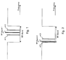
Fig. 1 illustrates the operation of a prior art multi-carrier receiver. The
receiver receives a multi-carrier signal containing for instance 1024 carriers
modulated with digital data. The interspacing between two carriers equals
4.3125 kHz. Part of the carriers have frequencies inside the Radio Frequency
Interference band, RFI-Band in Fig. 1. This RFI-Band is a predetermined,
standardised frequency interval reserved for e.g. radio amateur transmission. To
avoid disturbance of the radio amateur emission in the RFI-Band, the power
spectral density of the multi-carrier signal within this RFI-Band should be -80
dB/Hz or -60 dB/Hz. This is drawn in Fig. 1, and implies that only a very limited
amount of power and data bits can be allocated to the carriers having
frequencies within this RFI-Band. The prior art multi-carrier receiver contains
circuitry and software to roughly determine the location of a narrowband
disturber RFI-Signal-1, e.g. a radio amateur signal, in the RFI-Band. Thereupon,
the prior art multi-carrier receiver selects two carriers having frequencies inside
the RFI-Band to act as antennas, A1 1 and A12. The receiver senses the level of
the signal received at the frequencies of the antennas A11 and A12, and with this
information estimates the characteristics of the narrowband disturber RFI-Signal
1. An accurate estimation of the characteristics of the narrowband disturber, RFI-Signal-1,
enables the multi-carrier receiver to compensate for the effects of the
disturber. This is important, in particular because the tail of the narrowband
disturber which is due to harmonics, might affect the carriers outside the RFI-Band
that carry large amounts of data bits. In case the antennas A11 and A12
are chosen close to the narrowband disturber RFI-Signal-1, the characteristics of
the peak of the narrowband disturber can be estimated accurately, but the tail
cannot be estimated accurately. If on the other hand the antennas A11 and A12
are chosen far away from the narrowband disturber RFI-Signal-1, the effect of
the narrowband disturber RFI-Signal-1 at the frequency of the antennas may stay
below the noise level, so that the receiver senses the noise instead of the
disturbance coming from RFI-Signal-1. The location of the antennas A11 and
A12 relative to the frequency of the narrowband disturber RFI-Signal-1 is thus
critical. For a narrowband disturber RFI-Signal-1 that is located optimally, i.e. in
the middle of the RFI-Band like is drawn in Fig. 1, the prior art receiver can
always select a pair of antennas, A11 and A12, that enable an accurate
estimation of the characteristics of the narrowband disturber. For a narrowband
disturber RFI-Signal-2 that is located sub-optimally, i.e. near an edge of the RFI-Band
as is drawn in Fig. 2, the prior art receiver has to select one antenna A21
close to the narrowband disturber RFI-Signal-2, or has to select the two antennas
on one side of the narrowband disturber RFI-Signal-2. Both choices do not
enable the receiver to accurately estimate and compensate for the RFI disturber
RFI-Signal-2. As a consequence, the minimum guaranteed capacity decreases as
already explained in the introductory part of this patent application.
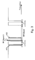
Fig. 3 illustrates the working of a multi-carrier system according to the
present invention. Apart from the carriers having frequencies in RFI-Band, two
other carriers C1 and C2 are kept zero. This means that no data bits and no
power is allocated to the carriers C1 and C2, although these carriers do not have
frequencies within the RFI-Band. Carrier C1, as is denoted in Fig. 3, is located at
a frequency 17 times 4.3125 kHz below the lower edge of the RFI-Band, whereas
carrier C2 is located at a frequency 17 times 4.3125 kHz above the upper edge
of the RFI-Band. The receiver according to the present invention again contains
circuitry or software to roughly estimate the location of a narrowband disturber
RFI-Signal-3. If this narrowband disturber RFI-Signal-3 is located near the lower
edge of the RFI-Band, like is depicted in Fig. 3, the multi-carrier receiver
according to the present invention selects carrier C1 as the first antenna and
another carrier A32 inside the RFI-Band as second antenna for estimating the
characteristics of the narrowband disturber RFI-Signal-3. If the narrowband
disturber would be located in the middle of the RFI-Band, the multi-carrier
receiver will select the two antennas within the RFI-Band, similar to the situation
depicted in Fig. 1 for the prior art multi-carrier receiver. In case the narrowband
disturber has a peak frequency close to the upper edge of the RFI-Band, the
multi-carrier receiver will select a first antenna within the RFI-Band and will select
carrier C2 as second antenna. Once the antennas are selected, the procedure or
algorithm used for determining the characteristics of the narrowband disturber
could be manifold, depending on the application and assumptions made.
It is noticed that applicability of the present invention is not limited to
multi-carrier receivers which also have the capability to assign amounts of power
and data bits to the different carriers. In an ADSL (Asymmetric Digital Subscriber
Line) or VDSL (Very High Speed Digital Subscriber Line) environment, this is the
responsibility of the receiver, but any person skilled in the art can imagine that
assigning bits and gains to individual carriers could also be the responsibility of
the transmitter, a unit separated from the transmitter and receiver, or could even
be predetermined by a standard specification. The concept of selecting the
antennas at the receiver amongst carriers inside the RFI-Band and at least two
carriers outside the RFI-Band can be implemented irrespective of the location of
the functionality that assigns bits and gains.
It is also remarked that applicability of the concept according to the
present invention is not limited to a particular modulation type such as DMT
(Discrete Multi Tone), Zipper, OFDM (Orthogonal Frequency Division
Multiplexing), ... or to a particular application such as ADSL, VDSL. The present
invention provides an advantageous solution to cope with narrowband interferers
in any multi-carrier transmission system without drastically affecting the minimum
guaranteed capacity.
A further remark is that the functionality to select the antennas for
estimating RFI characteristics may be implemented in hardware, in software, or
partially in hardware and partially in software. The precise algorithm or selection
criteria for the antennas can be manifold, but since the inventive nature of the
present invention is not in the criteria used for selecting the antennas, this aspect
is not further deepened in this patent application.
While the principles of the invention have been described above in
connection with specific apparatus, it is to be clearly understood that this
description is made only by way of example and not as a limitation on the scope
of the invention.