EP1237298B1 - Méthode de commande pour un système répéteur comportant une fonction de prévention des oscillations et une fonction de mise hors service de la sortie retour pour non-abonnés - Google Patents
Méthode de commande pour un système répéteur comportant une fonction de prévention des oscillations et une fonction de mise hors service de la sortie retour pour non-abonnés Download PDFInfo
- Publication number
- EP1237298B1 EP1237298B1 EP01104878A EP01104878A EP1237298B1 EP 1237298 B1 EP1237298 B1 EP 1237298B1 EP 01104878 A EP01104878 A EP 01104878A EP 01104878 A EP01104878 A EP 01104878A EP 1237298 B1 EP1237298 B1 EP 1237298B1
- Authority
- EP
- European Patent Office
- Prior art keywords
- signal
- power
- output
- receiver
- detect
- Prior art date
- Legal status (The legal status is an assumption and is not a legal conclusion. Google has not performed a legal analysis and makes no representation as to the accuracy of the status listed.)
- Expired - Lifetime
Links
- 230000010355 oscillation Effects 0.000 title claims abstract description 32
- 238000000034 method Methods 0.000 title claims abstract description 15
- 230000000630 rising effect Effects 0.000 claims description 23
- 230000003111 delayed effect Effects 0.000 claims description 10
- 230000005540 biological transmission Effects 0.000 claims description 2
- 238000001514 detection method Methods 0.000 abstract description 4
- 238000010897 surface acoustic wave method Methods 0.000 description 9
- 238000010586 diagram Methods 0.000 description 8
- 230000002159 abnormal effect Effects 0.000 description 3
- 238000004891 communication Methods 0.000 description 2
- 238000001914 filtration Methods 0.000 description 2
- 238000010295 mobile communication Methods 0.000 description 2
- 230000008878 coupling Effects 0.000 description 1
- 238000010168 coupling process Methods 0.000 description 1
- 238000005859 coupling reaction Methods 0.000 description 1
- 230000007547 defect Effects 0.000 description 1
- 238000009434 installation Methods 0.000 description 1
- 238000012986 modification Methods 0.000 description 1
- 230000004048 modification Effects 0.000 description 1
Images

Classifications
-
- H—ELECTRICITY
- H04—ELECTRIC COMMUNICATION TECHNIQUE
- H04B—TRANSMISSION
- H04B7/00—Radio transmission systems, i.e. using radiation field
- H04B7/14—Relay systems
- H04B7/15—Active relay systems
- H04B7/155—Ground-based stations
- H04B7/15528—Control of operation parameters of a relay station to exploit the physical medium
- H04B7/15535—Control of relay amplifier gain
-
- H—ELECTRICITY
- H04—ELECTRIC COMMUNICATION TECHNIQUE
- H04B—TRANSMISSION
- H04B7/00—Radio transmission systems, i.e. using radiation field
- H04B7/14—Relay systems
- H04B7/15—Active relay systems
- H04B7/155—Ground-based stations
- H04B7/15564—Relay station antennae loop interference reduction
Definitions
- non-service areas including underground areas of a large building, interior space of a high-rise building.
- the repeater systems may have self-oscillations depending on the installation place or according to circumstances.
- the forward oscillation causes no more than a failure of connection to the corresponding service area, but the reverse oscillation results in serious defects in a reception path of the base station transceiver system connected to the repeater systems.
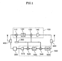
- the repeater system includes: a first duplexer 400 for transmitting data from an external base station transceiver system on a corresponding path; a transmitter 100 for amplifying a signal received from the first duplexer 400 into a service frequency; a second duplexer 600 for transmitting the output signal of the transmitter 100 to a mobile station located in a corresponding service area in a wireless manner, and receiving a signal from the mobile station; a receiver 500 for amplifying the signal received from the second duplexer 600; and a controller 200 coupled to the output signal of the receiver 500 for detecting the power level of the receiver 500, the controller 200 preventing the output of the receiver 500 being sent to the first duplexer 400 when the detected power level is above a first reference value during a first time period or below a second reference value during a second time period.
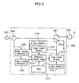
- FIG. 2 is a detailed diagram of the controller 200 shown in FIG. 1 .
- the transmitter 100 includes: a first mixer 110 for converting a signal having a high frequency received from the first duplexer 400 to a signal having an intermediate frequency; a first surface acoustic wave (SAW) filter 120 for filtering the output signal of the first mixer 110 and outputting a desired signal having an intermediate frequency; a second mixer 130 for modulating the output signal of the first SAW filter 120 to a signal having a high frequency; and a first power amplifier 140 for amplifying the output signal of the second mixer 130 and outputting the amplified signal to the second duplexer 600.
- SAW surface acoustic wave
- the first mixer 110 converts the signal having a high frequency from the duplexer 400 to a signal having an intermediate frequency, and simultaneously, receives a signal having a frequency for intermediate frequency modulation from an oscillator 300.
- the first SAW filter 120 filters the output of the first mixer 110 and outputs a signal having an intermediate frequency.
- the second mixer 130 modulates the output signal of the first SAW filter 120 into a signal having a high frequency, and simultaneously, receives a signal having a frequency for high frequency modulation from the oscillator 300.
- the second duplexer 600 sends this signal to the mobile telephone of the subscriber via an antenna. Then, the subscriber in the corresponding service area receives the signal.
- the signal output from the mobile telephone of the subscriber is input to the second duplexer 600, amplified at the low-noise amplifier 550 and converted to a signal having an intermediate frequency at the third mixer 540.
- the second SAW filter 530 filters the output signal of the third mixer 540 and outputs a signal having an intermediate frequency.
- the fourth mixer 520 modulates the output signal of the second SAW filter 530 into a signal having a high frequency.
- the signal having a high frequency is amplified at the second power amplifier 510 and sent to the base station transceiver system via the controller 200 and the first duplexer 400 in a wireless manner.
- the mobile telephone gets in connection to the base station transceiver system in the above-described procedure.
- the second power amplifier 510 has a very low power and the power oscillates, in which case the controller 200 interrupts the output signal of the second power amplifier 510 on the reverse channel, i.e., to the first duplexer 400.
- the subscriber can adjust a voltage corresponding to the high and low limits using switches 212 and 216, and enables/disables both an oscillation preventing function and an automatic reverse output disabling function for non-subscriber intervals when no subscriber exists in the corresponding service area.
- FIG. 3 is a timing diagram showing a logic flow in the controller 300.
- the high level detector 220 of the controller 200 detects a high level component from the output of the second power amplifier 510 via a coupler 240, i.e., a highest access signal of the subscriber or an oscillation power level.
- the high level detector 220 detects the reverse access signal of the subscriber, a talking signal and an oscillation signal. If the detected level is above a predetermined reference value, i.e., in case of high-level detect, very high access signal or oscillation, the high level detector 220 generates a high-level power detect signal and a delayed detect signal DELAYED DETECT having the same power level as the power level detect signal.
- the high level detector 220 If the power detect signal POWER DETECT is 'high' and the delayed detect signal DELAYED DETECT is 'low', the high level detector 220 generates a rising signal RISING; and otherwise, the high level detector 220 generates a falling signal FALLING.
- the rising and falling signals RISING and FALLING are event triggers.
- the high limit check circuit 215 of the detector check logic circuit 210 turns off the switch SW1 immediately after a predetermined time T1 from generation of the rising signal, and checks the level of the power detect signal POWER DETECT for a predetermined time T2 when the switch SW1 is off. If the power detect signal POWER DETECT has a high level detected during the time T2, the high limit check circuit 215 turns on the switch SW1. Otherwise, if the power detect signal POWER DETECT has a low level detected during the time T2, the switch SW1 is turned off. In a case where a falling signal FALLING is generated prior to the time T1 from generation of the rising signal RISING, the rising signal RISING is generated again and the switch SW1 is not turned off until the time T1.
- the talking signal is continuously 'high' and hardly detected due to characteristic of the CDMA, with the oscillation signal continuously in a 'high' state.
- the switch SW1 is turned on again. If the oscillation signal is detected repeatedly in this case, the system is completely down (in order to protect the base station transceiver system because repeated oscillation implies something wrong, in which case the switch SW1 is not ON even if the subscriber has access to). With the high level signal detected, it is possible to discriminate oscillation signal, terminal access signal and terminal talking signal.
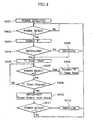
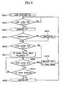
- FIG. 4 is a flowchart explaining an operation for programming the procedure.
- the high limit check circuit 215 determines in step 402 whether the power detect signal S1 is converted from low level “0" (in step 401) to high level "1".
- the high limit check circuit 215 turns the switch SW1 off and checks the level of the power detect signal POWER DETECT during a predetermined time T2 with the switch SW1 OFF, in step 410.
- the high limit check circuit 215 turns the switch SW1 on, in step 412.
- the high limit check circuit 215 turns the switch SW1 off.
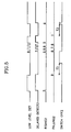
- FIG. 5 is a timing diagram showing a logic flow in the low limit check circuit 213 of the controller 300.
- the low level detector 230 of the controller 200 detects a low level component from the output of the second power amplifier 510 via the coupler 240, i.e., when no subscriber is connected.
- the low level detector 230 detects the reverse access signal of the subscriber, a talking signal and a non-signal output level. If the detected level is below a predetermined reference value, which implies that there is the non-signal output level without a reverse access signal of the subscriber nor a talking signal, the low level detector 230 turns the reverse output off to protect the reverse channel of the base station transceiver system.
- the low level detector 230 compares the detect signal being above a predetermine value to a delayed detect signal delayed detect2 to generate a rising signal RISING2 and a falling signal FALLING2, and after an elapse of a predetermined time T3 from generation of the falling signal FALLING2, turns the switch SW1 off.
- the low level detector 230 turns the switch SW1 on. As such, the reverse output of the repeater system is disabled without a subscriber connection, so that reduction of the reverse capacity of the base station transceiver system due to the repeater system can be improved.
- FIG. 6 is a flowchart explaining an operation for programming the procedure.
- the low limit check circuit 213 determines in step 602 whether the low level detect signal LOW LEVEL DETECT is converted from low level "0" (in step 601) to high level "1".
- the low limit check circuit 213 generates a rising signal RISING2 and determines in step 604 whether the switch SW1 is ON. If the switch SW1 is OFF, the low limit check circuit 213 turns the switch SW1 on and determines in step 606 whether the low level detect signal LOW LEVEL DETECT is "0".
- the low limit check circuit 213 If the low level detect signal LOW LEVEL DETECT is "0", the low limit check circuit 213 generates a falling signal FALLING2 and activates a timer T3, in step 607.
- the low limit check circuit 213 determines in step 608 whether the low level detect signal LOW LEVEL DETECT is "1" after generation of the falling signal FALLING2. If so, the low limit check circuit 213 generates a rising signal RISING2 and resets the timer, in step 609.
- the low limit check circuit 213 turns the switch SW1 off immediately.
- the present invention is not specifically limited to the PCS and may be applied to any general mobile communication system.
- the embodiment of the present invention provides a repeater system and a control method thereof, in which the reverse output of the repeater system is disabled upon detection of a non-subscriber interval in the service area or a reverse oscillation so as to prevent a drop in the capacity of a base station transceiver system and protect a reception path.
Landscapes
- Engineering & Computer Science (AREA)
- Computer Networks & Wireless Communication (AREA)
- Signal Processing (AREA)
- Radio Relay Systems (AREA)
- Mobile Radio Communication Systems (AREA)
- Interface Circuits In Exchanges (AREA)
- Selective Calling Equipment (AREA)
- Arrangements For Transmission Of Measured Signals (AREA)
Claims (2)
- Procédé pour contrôler un système répéteur comprenant :un émetteur (100) agencé pour :- amplifier des données reçues d'un système externe d'émetteurs-récepteurs de stations de base,- convertir les données amplifiées en un signal de service, et- envoyer sans-fil le signal de service à une station mobile dans une zone de service correspondante ;un récepteur (500) agencé pour amplifier le signal reçu de la station mobile et pour émettre le signal amplifié vers le système d'émetteurs-récepteurs de stations de base ; etun contrôleur (200), le contrôleur comprenant un détecteur de niveau haut (220) couplé à une sortie du récepteur (500), pour détecter un niveau de forte puissance du récepteur (500) ;un détecteur de niveau bas (230) couplé à la sortie du récepteur (500), pour détecter un niveau de faible puissance du récepteur (500) ;un circuit intégré (210) agencé pour générer un signal de contrôle pour empêcher la sortie du récepteur (500) d'être émise vers le système d'émetteurs-récepteurs de stations de base lorsque le niveau de puissance détecté par le détecteur de niveau haut (220) est supérieur à une première valeur de référence pendant une première période de temps (T1), ou lorsque le niveau de puissance détecté par le détecteur de niveau bas (230) est inférieur à une seconde valeur de référence pendant une deuxième période de temps (T2) ; etun commutateur (SW1) agencé pour valider ou invalider la transmission du signal de sortie du récepteur (500) vers le système d'émetteurs-récepteurs de stations de base sur la base du signal de contrôle du circuit intégré (210), le procédé pour contrôler le système répéteur comprenant les étapes de :- distinction entre un signal oscillant du système répéteur, un signal de voix et un signal d'accès, comprenant les étapes de :• détection d'un signal de niveau haut dans le détecteur de niveau haut, dans laquelle on génère un signal de détection de puissance (DETECTION DE PUISSANCE) et un signal de détection retardée (DETECTION RETARDÉE) ;• génération d'un signal montant (MONTANT) si le signal de détection de puissance (DETECTION DE PUISSANCE) est "haut" et le signal de détection retardée (DETECTION RETARDÉE) est "bas";• si un signal montant (MONTANT) est généré, le commutateur (SW1) est activé et un temporisateur est activé pendant une première période de temps prédéfinie (T1) de telle manière que lorsque le temporisateur pour la première période de temps prédéfinie (T1) se termine alors que le signal de détection de puissance (DETECTION DE PUISSANCE) n'est pas "bas" après le signal montant (MONTANT), le commutateur (SW1) est désactivé et le signal de détection de puissance (DETECTION DE PUISSANCE) est vérifié pendant une deuxième période de temps prédéfinie (T2), le commutateur (SW1) étant désactivé ; et• identification d'un signal non oscillant du système répéteur si le signal de détection de puissance (DETECTION DE PUISSANCE) est à un niveau haut pendant la deuxième période de temps prédéfinie (T2) et identification d'un signal oscillant du système répéteur si le signal de détection de puissance (DETECTION DE PUISSANCE) est à un niveau bas pendant la deuxième période de temps prédéfinie (T2) ;- invalidation de la sortie du récepteur (500) du système répéteur lorsque la puissance est en état d'oscillation ou lorsque le niveau de puissance détecté par le détecteur de niveau bas (230) est inférieur à une valeur prédéfinie pendant une troisième période de temps (T3) ; et- validation de la sortie du récepteur (500) du système répéteur lorsque la puissance n'est pas en état d'oscillation et la sortie inverse est un signal d'accès ou de voix.
- Procédé selon la revendication 1 comprenant en outre les étapes de :- détermination que la puissance a une valeur minimum lorsqu'il n'y a pas d'abonné pendant un temps prédéfini ;- invalidation de la sortie du récepteur (500) du système répéteur lorsque la puissance reste à la valeur minimum ; et- entretien de la sortie du récepteur (500) du système répéteur en utilisant le signal d'accès de l'abonné lorsque l'abonné essaie de se connecter pendant que la sortie inverse du système répéteur est invalidée.
Priority Applications (4)
| Application Number | Priority Date | Filing Date | Title |
|---|---|---|---|
| AT01104878T ATE407484T1 (de) | 2001-02-28 | 2001-02-28 | Regelverfahren für ein relaissystem mit funktion zum unterdrücken von schwingungen sowie einer automatischen abschaltfunktion des ausgangs für nichtteilnehmer |
| DE60135630T DE60135630D1 (de) | 2001-02-28 | 2001-02-28 | Regelverfahren für ein Relaissystem mit Funktion zum Unterdrücken von Schwingungen sowie einer automatischen Abschaltfunktion des Ausgangs für Nichtteilnehmer |
| EP01104878A EP1237298B1 (fr) | 2001-02-28 | 2001-02-28 | Méthode de commande pour un système répéteur comportant une fonction de prévention des oscillations et une fonction de mise hors service de la sortie retour pour non-abonnés |
| HK02106794.3A HK1045417B (en) | 2001-02-28 | 2002-09-17 | Control method for a repeater system having oscillation preventing function and automatic reverse output disabling function for non-subscriber |
Applications Claiming Priority (1)
| Application Number | Priority Date | Filing Date | Title |
|---|---|---|---|
| EP01104878A EP1237298B1 (fr) | 2001-02-28 | 2001-02-28 | Méthode de commande pour un système répéteur comportant une fonction de prévention des oscillations et une fonction de mise hors service de la sortie retour pour non-abonnés |
Publications (2)
| Publication Number | Publication Date |
|---|---|
| EP1237298A1 EP1237298A1 (fr) | 2002-09-04 |
| EP1237298B1 true EP1237298B1 (fr) | 2008-09-03 |
Family
ID=8176627
Family Applications (1)
| Application Number | Title | Priority Date | Filing Date |
|---|---|---|---|
| EP01104878A Expired - Lifetime EP1237298B1 (fr) | 2001-02-28 | 2001-02-28 | Méthode de commande pour un système répéteur comportant une fonction de prévention des oscillations et une fonction de mise hors service de la sortie retour pour non-abonnés |
Country Status (4)
| Country | Link |
|---|---|
| EP (1) | EP1237298B1 (fr) |
| AT (1) | ATE407484T1 (fr) |
| DE (1) | DE60135630D1 (fr) |
| HK (1) | HK1045417B (fr) |
Families Citing this family (1)
| Publication number | Priority date | Publication date | Assignee | Title |
|---|---|---|---|---|
| TWI511473B (zh) | 2013-07-01 | 2015-12-01 | Ind Tech Res Inst | 電子裝置與控制方法 |
Citations (1)
| Publication number | Priority date | Publication date | Assignee | Title |
|---|---|---|---|---|
| US3411088A (en) * | 1965-02-09 | 1968-11-12 | Bell Telephone Labor Inc | Automatic input power level adjustment apparatus for amplifier of a broadband repeater |
Family Cites Families (3)
| Publication number | Priority date | Publication date | Assignee | Title |
|---|---|---|---|---|
| JP2755241B2 (ja) * | 1995-08-25 | 1998-05-20 | 住友電気工業株式会社 | 無線中継器用発振検出装置およびこの装置が適用された無線中継器 |
| US5835848A (en) * | 1996-12-30 | 1998-11-10 | Lucent Technologies Inc. | Range repeater for a transmission system |
| JPH10313271A (ja) * | 1997-05-12 | 1998-11-24 | Kokusai Electric Co Ltd | 周波数選択形無線中継装置の異常発振検出回路 |
-
2001
- 2001-02-28 EP EP01104878A patent/EP1237298B1/fr not_active Expired - Lifetime
- 2001-02-28 AT AT01104878T patent/ATE407484T1/de not_active IP Right Cessation
- 2001-02-28 DE DE60135630T patent/DE60135630D1/de not_active Expired - Lifetime
-
2002
- 2002-09-17 HK HK02106794.3A patent/HK1045417B/en not_active IP Right Cessation
Patent Citations (1)
| Publication number | Priority date | Publication date | Assignee | Title |
|---|---|---|---|---|
| US3411088A (en) * | 1965-02-09 | 1968-11-12 | Bell Telephone Labor Inc | Automatic input power level adjustment apparatus for amplifier of a broadband repeater |
Also Published As
| Publication number | Publication date |
|---|---|
| DE60135630D1 (de) | 2008-10-16 |
| HK1045417A1 (en) | 2002-11-22 |
| ATE407484T1 (de) | 2008-09-15 |
| HK1045417B (en) | 2008-11-28 |
| EP1237298A1 (fr) | 2002-09-04 |
Similar Documents
| Publication | Publication Date | Title |
|---|---|---|
| US5950127A (en) | Mode switching method for mobile station | |
| US6493537B1 (en) | Apparatus and method for preventing oscillations in a radio repeater device | |
| US6748194B2 (en) | Repeater system having oscillation preventing function and automatic reverse output disabling function for non-subscriber and control method thereof | |
| US5515365A (en) | Method and apparatus for reducing interference in a time division duplex communication system | |
| WO1997049255A1 (fr) | Procede et systeme de suppression des parasites imputables aux appareils de communication mobile | |
| EP0746951A1 (fr) | Procede de transmission d'appels de priorities differentes dans un reseau cellulaire | |
| US7103321B2 (en) | Power amplifier bypass in a half-duplex IC | |
| KR100385611B1 (ko) | 이동통신시스템의 무선 중계장치 | |
| AU662449B2 (en) | An apparatus and a method for preserving coverage in an overlapping coverage area | |
| KR100573932B1 (ko) | 발진 방지기능 및 무가입자시 역방향 출력 자동 차단 기능을갖는 중계기 시스템 및 그 제어방법 | |
| KR20030049031A (ko) | 전력제어 기능을 갖는 중간 주파수 방식의 중계기와전력제어 방법 | |
| EP1237298B1 (fr) | Méthode de commande pour un système répéteur comportant une fonction de prévention des oscillations et une fonction de mise hors service de la sortie retour pour non-abonnés | |
| KR970007608B1 (ko) | 송신에러제어장치를 갖는 디지탈 무선통신장치 | |
| KR100604677B1 (ko) | 귀환신호 제거 및 출력세기 자동 제어 기능을 구비한 코드분할 다중 접속방식 무선중계장치 | |
| US5548799A (en) | Mobile communication system having a control for limiting the number of carriers based on the level of intermodulation distortion | |
| JP3809725B2 (ja) | 周波数ホッピング方式を用いた無線通信装置 | |
| KR100376416B1 (ko) | 이동통신 중계기 발진검출 및 방지시스템 | |
| JP2003309512A (ja) | 無線通信端末 | |
| KR100324027B1 (ko) | 중계기의 동작 제어회로 | |
| JPH08331015A (ja) | 中継増幅装置 | |
| KR0184488B1 (ko) | 무선호출기의 상호 변조 방지회로 및 방법 | |
| KR20030050540A (ko) | 발진방지기능을 갖는 씨디엠에이통신시스템용무선중계장치 | |
| JP3054901B2 (ja) | 移動無線受信方法および装置 | |
| KR20060019633A (ko) | 발진 방지기능 및 무가입자시 역방향 출력 자동 차단기능을 갖는 중계기 시스템 | |
| KR100281627B1 (ko) | 무선통신 중계기의 노이즈 감소 회로 |
Legal Events
| Date | Code | Title | Description |
|---|---|---|---|
| PUAI | Public reference made under article 153(3) epc to a published international application that has entered the european phase |
Free format text: ORIGINAL CODE: 0009012 |
|
| 17P | Request for examination filed |
Effective date: 20011027 |
|
| AK | Designated contracting states |
Kind code of ref document: A1 Designated state(s): AT BE CH CY DE DK ES FI FR GB GR IE IT LI LU MC NL PT SE TR |
|
| AX | Request for extension of the european patent |
Free format text: AL;LT;LV;MK;RO;SI |
|
| RAP1 | Party data changed (applicant data changed or rights of an application transferred) |
Owner name: KTFREETEL CO., LTD |
|
| AKX | Designation fees paid | ||
| RBV | Designated contracting states (corrected) |
Designated state(s): AT BE CH CY DE DK ES FI FR GB GR IE IT LI LU MC NL PT SE TR |
|
| REG | Reference to a national code |
Ref country code: DE Ref legal event code: 8566 |
|
| 17Q | First examination report despatched |
Effective date: 20050627 |
|
| 17Q | First examination report despatched |
Effective date: 20050627 |
|
| RTI1 | Title (correction) |
Free format text: CONTROL METHOD FOR A REPEATER SYSTEM HAVING OSCILLATION PREVENTING FUNCTION AND AUTOMATIC REVERSE OUTPUT DISABLING FUNCTION FOR NON-SUBSCRIBER |
|
| GRAP | Despatch of communication of intention to grant a patent |
Free format text: ORIGINAL CODE: EPIDOSNIGR1 |
|
| GRAS | Grant fee paid |
Free format text: ORIGINAL CODE: EPIDOSNIGR3 |
|
| GRAA | (expected) grant |
Free format text: ORIGINAL CODE: 0009210 |
|
| AK | Designated contracting states |
Kind code of ref document: B1 Designated state(s): AT BE CH CY DE DK ES FI FR GB GR IE IT LI LU MC NL PT SE TR |
|
| REG | Reference to a national code |
Ref country code: GB Ref legal event code: FG4D |
|
| REG | Reference to a national code |
Ref country code: CH Ref legal event code: EP |
|
| REG | Reference to a national code |
Ref country code: IE Ref legal event code: FG4D |
|
| REF | Corresponds to: |
Ref document number: 60135630 Country of ref document: DE Date of ref document: 20081016 Kind code of ref document: P |
|
| REG | Reference to a national code |
Ref country code: SE Ref legal event code: TRGR |
|
| REG | Reference to a national code |
Ref country code: HK Ref legal event code: GR Ref document number: 1045417 Country of ref document: HK |
|
| PG25 | Lapsed in a contracting state [announced via postgrant information from national office to epo] |
Ref country code: ES Free format text: LAPSE BECAUSE OF FAILURE TO SUBMIT A TRANSLATION OF THE DESCRIPTION OR TO PAY THE FEE WITHIN THE PRESCRIBED TIME-LIMIT Effective date: 20081214 |
|
| PG25 | Lapsed in a contracting state [announced via postgrant information from national office to epo] |
Ref country code: AT Free format text: LAPSE BECAUSE OF FAILURE TO SUBMIT A TRANSLATION OF THE DESCRIPTION OR TO PAY THE FEE WITHIN THE PRESCRIBED TIME-LIMIT Effective date: 20080903 |
|
| PG25 | Lapsed in a contracting state [announced via postgrant information from national office to epo] |
Ref country code: BE Free format text: LAPSE BECAUSE OF FAILURE TO SUBMIT A TRANSLATION OF THE DESCRIPTION OR TO PAY THE FEE WITHIN THE PRESCRIBED TIME-LIMIT Effective date: 20080903 |
|
| PG25 | Lapsed in a contracting state [announced via postgrant information from national office to epo] |
Ref country code: PT Free format text: LAPSE BECAUSE OF FAILURE TO SUBMIT A TRANSLATION OF THE DESCRIPTION OR TO PAY THE FEE WITHIN THE PRESCRIBED TIME-LIMIT Effective date: 20090203 |
|
| PLBE | No opposition filed within time limit |
Free format text: ORIGINAL CODE: 0009261 |
|
| STAA | Information on the status of an ep patent application or granted ep patent |
Free format text: STATUS: NO OPPOSITION FILED WITHIN TIME LIMIT |
|
| PG25 | Lapsed in a contracting state [announced via postgrant information from national office to epo] |
Ref country code: DK Free format text: LAPSE BECAUSE OF FAILURE TO SUBMIT A TRANSLATION OF THE DESCRIPTION OR TO PAY THE FEE WITHIN THE PRESCRIBED TIME-LIMIT Effective date: 20080903 |
|
| 26N | No opposition filed |
Effective date: 20090604 |
|
| PG25 | Lapsed in a contracting state [announced via postgrant information from national office to epo] |
Ref country code: IT Free format text: LAPSE BECAUSE OF FAILURE TO SUBMIT A TRANSLATION OF THE DESCRIPTION OR TO PAY THE FEE WITHIN THE PRESCRIBED TIME-LIMIT Effective date: 20080903 |
|
| PG25 | Lapsed in a contracting state [announced via postgrant information from national office to epo] |
Ref country code: MC Free format text: LAPSE BECAUSE OF NON-PAYMENT OF DUE FEES Effective date: 20090228 |
|
| REG | Reference to a national code |
Ref country code: CH Ref legal event code: PL |
|
| PG25 | Lapsed in a contracting state [announced via postgrant information from national office to epo] |
Ref country code: LI Free format text: LAPSE BECAUSE OF NON-PAYMENT OF DUE FEES Effective date: 20090228 Ref country code: CH Free format text: LAPSE BECAUSE OF NON-PAYMENT OF DUE FEES Effective date: 20090228 |
|
| PG25 | Lapsed in a contracting state [announced via postgrant information from national office to epo] |
Ref country code: IE Free format text: LAPSE BECAUSE OF NON-PAYMENT OF DUE FEES Effective date: 20090228 |
|
| PG25 | Lapsed in a contracting state [announced via postgrant information from national office to epo] |
Ref country code: GR Free format text: LAPSE BECAUSE OF FAILURE TO SUBMIT A TRANSLATION OF THE DESCRIPTION OR TO PAY THE FEE WITHIN THE PRESCRIBED TIME-LIMIT Effective date: 20081204 |
|
| PG25 | Lapsed in a contracting state [announced via postgrant information from national office to epo] |
Ref country code: LU Free format text: LAPSE BECAUSE OF NON-PAYMENT OF DUE FEES Effective date: 20090228 |
|
| PG25 | Lapsed in a contracting state [announced via postgrant information from national office to epo] |
Ref country code: TR Free format text: LAPSE BECAUSE OF FAILURE TO SUBMIT A TRANSLATION OF THE DESCRIPTION OR TO PAY THE FEE WITHIN THE PRESCRIBED TIME-LIMIT Effective date: 20080903 |
|
| PG25 | Lapsed in a contracting state [announced via postgrant information from national office to epo] |
Ref country code: CY Free format text: LAPSE BECAUSE OF FAILURE TO SUBMIT A TRANSLATION OF THE DESCRIPTION OR TO PAY THE FEE WITHIN THE PRESCRIBED TIME-LIMIT Effective date: 20080903 |
|
| REG | Reference to a national code |
Ref country code: FR Ref legal event code: PLFP Year of fee payment: 16 |
|
| REG | Reference to a national code |
Ref country code: FR Ref legal event code: PLFP Year of fee payment: 17 |
|
| REG | Reference to a national code |
Ref country code: FR Ref legal event code: PLFP Year of fee payment: 18 |
|
| PGFP | Annual fee paid to national office [announced via postgrant information from national office to epo] |
Ref country code: DE Payment date: 20190122 Year of fee payment: 19 Ref country code: GB Payment date: 20190125 Year of fee payment: 19 Ref country code: NL Payment date: 20190128 Year of fee payment: 19 Ref country code: FI Payment date: 20190123 Year of fee payment: 19 Ref country code: FR Payment date: 20190123 Year of fee payment: 19 |
|
| PGFP | Annual fee paid to national office [announced via postgrant information from national office to epo] |
Ref country code: SE Payment date: 20190128 Year of fee payment: 19 |
|
| REG | Reference to a national code |
Ref country code: DE Ref legal event code: R119 Ref document number: 60135630 Country of ref document: DE |
|
| REG | Reference to a national code |
Ref country code: FI Ref legal event code: MAE |
|
| REG | Reference to a national code |
Ref country code: NL Ref legal event code: MM Effective date: 20200301 |
|
| GBPC | Gb: european patent ceased through non-payment of renewal fee |
Effective date: 20200228 |
|
| PG25 | Lapsed in a contracting state [announced via postgrant information from national office to epo] |
Ref country code: FI Free format text: LAPSE BECAUSE OF NON-PAYMENT OF DUE FEES Effective date: 20200228 |
|
| PG25 | Lapsed in a contracting state [announced via postgrant information from national office to epo] |
Ref country code: NL Free format text: LAPSE BECAUSE OF NON-PAYMENT OF DUE FEES Effective date: 20200301 |
|
| PG25 | Lapsed in a contracting state [announced via postgrant information from national office to epo] |
Ref country code: FR Free format text: LAPSE BECAUSE OF NON-PAYMENT OF DUE FEES Effective date: 20200229 Ref country code: SE Free format text: LAPSE BECAUSE OF NON-PAYMENT OF DUE FEES Effective date: 20200229 Ref country code: GB Free format text: LAPSE BECAUSE OF NON-PAYMENT OF DUE FEES Effective date: 20200228 Ref country code: DE Free format text: LAPSE BECAUSE OF NON-PAYMENT OF DUE FEES Effective date: 20200901 |