EP1237251A2 - Echange de données dans un bus de données - Google Patents
Echange de données dans un bus de données Download PDFInfo
- Publication number
- EP1237251A2 EP1237251A2 EP02100143A EP02100143A EP1237251A2 EP 1237251 A2 EP1237251 A2 EP 1237251A2 EP 02100143 A EP02100143 A EP 02100143A EP 02100143 A EP02100143 A EP 02100143A EP 1237251 A2 EP1237251 A2 EP 1237251A2
- Authority
- EP
- European Patent Office
- Prior art keywords
- bus
- data
- branches
- branch
- transceivers
- Prior art date
- Legal status (The legal status is an assumption and is not a legal conclusion. Google has not performed a legal analysis and makes no representation as to the accuracy of the status listed.)
- Granted
Links
Images

Classifications
-
- H—ELECTRICITY
- H04—ELECTRIC COMMUNICATION TECHNIQUE
- H04L—TRANSMISSION OF DIGITAL INFORMATION, e.g. TELEGRAPHIC COMMUNICATION
- H04L25/00—Baseband systems
- H04L25/02—Details ; arrangements for supplying electrical power along data transmission lines
- H04L25/08—Modifications for reducing interference; Modifications for reducing effects due to line faults ; Receiver end arrangements for detecting or overcoming line faults
- H04L25/085—Arrangements for reducing interference in line transmission systems, e.g. by differential transmission
-
- H—ELECTRICITY
- H04—ELECTRIC COMMUNICATION TECHNIQUE
- H04B—TRANSMISSION
- H04B1/00—Details of transmission systems, not covered by a single one of groups H04B3/00 - H04B13/00; Details of transmission systems not characterised by the medium used for transmission
- H04B1/74—Details of transmission systems, not covered by a single one of groups H04B3/00 - H04B13/00; Details of transmission systems not characterised by the medium used for transmission for increasing reliability, e.g. using redundant or spare channels or apparatus
-
- H—ELECTRICITY
- H04—ELECTRIC COMMUNICATION TECHNIQUE
- H04B—TRANSMISSION
- H04B3/00—Line transmission systems
- H04B3/02—Details
- H04B3/36—Repeater circuits
-
- H—ELECTRICITY
- H04—ELECTRIC COMMUNICATION TECHNIQUE
- H04L—TRANSMISSION OF DIGITAL INFORMATION, e.g. TELEGRAPHIC COMMUNICATION
- H04L12/00—Data switching networks
- H04L12/28—Data switching networks characterised by path configuration, e.g. LAN [Local Area Networks] or WAN [Wide Area Networks]
- H04L12/40—Bus networks
- H04L12/40006—Architecture of a communication node
- H04L12/40013—Details regarding a bus controller
-
- H—ELECTRICITY
- H04—ELECTRIC COMMUNICATION TECHNIQUE
- H04L—TRANSMISSION OF DIGITAL INFORMATION, e.g. TELEGRAPHIC COMMUNICATION
- H04L25/00—Baseband systems
- H04L25/02—Details ; arrangements for supplying electrical power along data transmission lines
- H04L25/03—Shaping networks in transmitter or receiver, e.g. adaptive shaping networks
- H04L25/03878—Line equalisers; line build-out devices
-
- B—PERFORMING OPERATIONS; TRANSPORTING
- B60—VEHICLES IN GENERAL
- B60R—VEHICLES, VEHICLE FITTINGS, OR VEHICLE PARTS, NOT OTHERWISE PROVIDED FOR
- B60R16/00—Electric or fluid circuits specially adapted for vehicles and not otherwise provided for; Arrangement of elements of electric or fluid circuits specially adapted for vehicles and not otherwise provided for
- B60R16/02—Electric or fluid circuits specially adapted for vehicles and not otherwise provided for; Arrangement of elements of electric or fluid circuits specially adapted for vehicles and not otherwise provided for electric constitutive elements
- B60R16/03—Electric or fluid circuits specially adapted for vehicles and not otherwise provided for; Arrangement of elements of electric or fluid circuits specially adapted for vehicles and not otherwise provided for electric constitutive elements for supply of electrical power to vehicle subsystems or for
-
- G—PHYSICS
- G06—COMPUTING OR CALCULATING; COUNTING
- G06F—ELECTRIC DIGITAL DATA PROCESSING
- G06F11/00—Error detection; Error correction; Monitoring
- G06F11/07—Responding to the occurrence of a fault, e.g. fault tolerance
- G06F11/0796—Safety measures, i.e. ensuring safe condition in the event of error, e.g. for controlling element
Definitions
- the invention relates to a method for data exchange on a data bus and a data bus with at least two decoupled bus branches, especially for the Automotive technology.
- Data buses are increasingly used in automotive technology Indent. In the event of a short circuit on a bus line or contact with another potential (external fault) there can be a total loss of communication. A defective bus participant can also exchange data bring it to a standstill if it permanently turns the bus line on sets a certain potential. This is especially for safety-related applications in a motor vehicle problematic.
- the patent specification EP 0 412 085 B1 relates to a network interface, in the event of an open or short circuit one connected to the network interface Bus line can be recognized even if the Network interface in an inactive operating mode ("sleep mode") is located.
- At least the data exchange By separating or decoupling the data bus in at least two bus branches in the event of a fault or one Defect on a bus line, at least the data exchange continue on one of the bus branches which is not a fault having.
- Such disturbances or defects are typical the faulty constant presence of a signal level (stuck at dominant state or stuck at recessive state) or the presence of an undefined signal level.
- Such a disturbance can occur, for example, with a local short circuit to ground or in the event of an external short circuit occur with a power supply.
- Bus branches reconnected when the Fault or error disappears or if the data bus is reset when switching on again.
- An indication of the disappearance of an error is if the Signal levels on the bus branches again predefined signal levels reach and / or if a transceiver of the decoupling circuit is able to control the signal level of the concerned bus branch within the predetermined level to change.
- a combination of the bus branches only when switching on again.
- the data exchange preferably takes place on the data bus with pulse code modulated data in NRZ (no return to zero) and bit stuffing to interrupt long ones High or low bit sequences.
- bit stream can be synchronized by means of a Coding must be coded.
- Preferred areas of application of the invention are security-relevant Applications in motor vehicles ("drive by wire), such as a data bus for an electromechanical Brake (“brake by wire”), an electromechanical Steering (“steer by wire”), an electronic accelerator pedal, Etc.
- drive by wire such as a data bus for an electromechanical Brake (“brake by wire”), an electromechanical Steering (“steer by wire”), an electronic accelerator pedal, Etc.
- Bus branch advantageously two actuators of an electromechanical Brake. This can be analogous to a conventional hydraulic two-circuit system by an intact one Two wheels are braked on the bus branch.
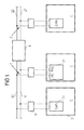
- the part of a data bus shown in FIG Motor vehicle has two bus branches 1 and 2 with bus lines 11, 12 and 21, 22 on, respectively, by a Isolation or decoupling circuit 4 physically from each other are separated or decoupled.
- the decoupling circuit 4 has a first state on where they have bidirectional communication between mediated the two bus branches and a state on, in which is used for communication between the two bus branches 1 and 2 prevents.
- a large number of bus users 3 or computing units are parallel to the bus lines 11, 12 and 21, 22 of the two bus branches 1, 2 connected.
- Each of the two bus branches 1, 2 has a plurality of subscribers 3.
- Participant 3 is a control system the (microprocessor), the commands to apply a wheel brake generated, and around control system (microprocessors), issue the received control commands to electric motors, to brake a wheel.
- Data is transferred on the bus lines by between defined, differential signal levels for one dominant state and changed for a recessive state becomes.
- the dominant state is that on the bus lines prevailing state when no signal from one Participant 3 is created.
- dominant state on a bus line a voltage of 3.5V and to the other bus line a voltage of 1.5V created. Both bus lines are in a recessive state supplied with 2.5V. This corresponds to the "unoccupied" Status.
- State and recessive state thus "overwrites" the dominant state the recessive state.
- the dominant state can be a certain voltage or current level, to which the logic state is high or Low is assigned.
- the level becomes the difference formed between the levels on the two bus lines 1 and 2.
- the signal level changes to change the logic state on both bus lines 11 and 12 or 21 and 22 changed.
- Each participant 3 is via a transceiver 5 connected to the bus lines 11, 12 and 21, 22, respectively.
- the Transceivers 5 convert those on the bus lines differential signal level into digital level for the Participant 3 and the digital TTL signal level of the sending Participant 3 in the predefined differential level on the bus lines.
- the data bus system including all connected ones Modules, is for communication according to a CAN protocol specified.
- the data exchange takes place using a time-controlled protocol (preferably TTP or Flexray), although communication in an event-controlled protocol is possible.
- TTP time-controlled protocol
- An advantage timed data communication consists of that data must be exchanged periodically and therefore an error is reliably detected when a data exchange for longer than a certain time interval.
- Figure 2 shows the decoupling circuit 4, the two transceivers 51 and 52, a data transfer logic 6, a measuring unit 7 and a monitoring unit 8.
- the bidirectional transceivers 51 and 52 read during of simultaneously sending data from the bus lines 11 and 12 or 21 and 22 back to the detection of a fault condition or a data transfer of a higher priority enable on the bus lines.
- the data transfer logic located between the transceivers 51 and 52 6's job is to prevent a from a transceiver 51, 52 to the bus lines (i.e. the "analog side" of the transceiver) of a first bus branch output dominant signal level read back again (on the "digital side” of the transceiver) and from second transceiver on the bus lines of the second bus branch is issued. Because doing so would become permanent the dominant signal level on the bus lines 11, 12 and 21, 22 of both bus branches 1, 2 are set. A communication of data would then no longer be possible.
- the data transfer logic thus ensures a transparent Behavior of the two connected to the decoupling circuit 4 Bus branches 1 and 2.
- the data transfer logic 6 can for example be simple digital logic modules or with a simple microprocessor can be realized by a small program is controlled accordingly.
- the term of one of signal or date received by a bus branch through the Decoupling circuit 4 should be at most half the duration the bus cycle defined by the system clock of the data bus be. The duration is preferably at most a third of the bus cycle.
- the monitoring unit 8 permanently monitors the signal levels, those on the bus lines 11, 12, 21, 22 of both bus branches issue. As a result, the monitoring unit 8 a faulty dominant state recognize the following with SADS (stuck at dominant state).
- SADS swipe at dominant state
- the monitoring unit 8 can also be used via the measuring unit 7 an erroneously persistent recessive state recognize the following with SARS (stuck at recessive state).
- SARS smoke at recessive state
- a SARS error occurs when as a result of an external short or a short circuit of the dominant state can no longer be set.
- This Faults are recognized by a resistance measurement.
- the Resistance between the two bus lines 11 and 12 or 21 and 22 is by their terminating resistors, not shown specified.
- the resistance measurement may communicate on the bus lines. This is also not shown in the figure known diode resistor circuit guaranteed.
- bus branches 1 or 2 Since a single fault only affects one of bus branches 1 or 2 may concern it is possible to exchange data on the to maintain another, intact bus branch. This is particularly useful if a participant or a Control unit, the actuators connected to the bus lines controls, either implemented redundantly for each bus branch or separate connections to the bus branches having.
- bus branches 1 and 2 become the decoupling circuit 4 restored to the state in which it Exchanged data between the two bus branches 1 and 2.
- bus branches 1 are interconnected and 2 when the system is reset due to a shutdown and switching on the system again (power-on reset).
- Figure 3 illustrates an electromechanical braking system with the data bus explained in the above figures.
- about one of the only partially shown bus branches 1 or 2 are two actuators (electric motors) 9 of an electromechanical Brake by means of the assigned Bus participants 3 or control units controllable.
- Actuators 9 connected to a bus branch are diagonally connected to different ones Vehicle axles arranged.
Landscapes
- Engineering & Computer Science (AREA)
- Computer Networks & Wireless Communication (AREA)
- Signal Processing (AREA)
- Power Engineering (AREA)
- Small-Scale Networks (AREA)
Applications Claiming Priority (2)
| Application Number | Priority Date | Filing Date | Title |
|---|---|---|---|
| DE10110267 | 2001-03-02 | ||
| DE10110267 | 2001-03-02 |
Publications (3)
| Publication Number | Publication Date |
|---|---|
| EP1237251A2 true EP1237251A2 (fr) | 2002-09-04 |
| EP1237251A3 EP1237251A3 (fr) | 2011-12-14 |
| EP1237251B1 EP1237251B1 (fr) | 2018-12-05 |
Family
ID=7676191
Family Applications (1)
| Application Number | Title | Priority Date | Filing Date |
|---|---|---|---|
| EP02100143.3A Expired - Lifetime EP1237251B1 (fr) | 2001-03-02 | 2002-02-19 | Echange de données dans un bus de données |
Country Status (1)
| Country | Link |
|---|---|
| EP (1) | EP1237251B1 (fr) |
Family Cites Families (8)
| Publication number | Priority date | Publication date | Assignee | Title |
|---|---|---|---|---|
| US4527237A (en) * | 1979-10-11 | 1985-07-02 | Nanodata Computer Corporation | Data processing system |
| DE19509558A1 (de) * | 1995-03-16 | 1996-09-19 | Abb Patent Gmbh | Verfahren zur fehlertoleranten Kommunikation unter hohen Echtzeitbedingungen |
| WO1996041273A1 (fr) * | 1995-06-07 | 1996-12-19 | International Business Machines Corporation | Dispositif et procede de commande d'un bus de donnees |
| DE19603221C1 (de) * | 1996-01-30 | 1997-01-30 | Daimler Benz Ag | Schaltungsanordnung zur signalübertragenden Kopplung von Datennetzen |
| US5999389A (en) * | 1996-10-24 | 1999-12-07 | Eaton Corporation | Repeater for bus with bus fault isolation |
| DE19805464A1 (de) * | 1998-02-11 | 1999-08-12 | Volkswagen Ag | Schaltungsanordnung zur Kommunikation und Diagnose einer Vielzahl elektrischer Komponenten |
| DE19938900C2 (de) * | 1999-08-17 | 2001-08-16 | Siemens Ag | Serieller Datenbus und Kommunikationsverfahren |
| DE19960859A1 (de) * | 1999-12-16 | 2001-07-05 | Trw Automotive Electron & Comp | Entkopplungseinheit für Bussysteme |
-
2002
- 2002-02-19 EP EP02100143.3A patent/EP1237251B1/fr not_active Expired - Lifetime
Also Published As
| Publication number | Publication date |
|---|---|
| EP1237251B1 (fr) | 2018-12-05 |
| EP1237251A3 (fr) | 2011-12-14 |
Similar Documents
| Publication | Publication Date | Title |
|---|---|---|
| EP0658258B1 (fr) | Interface de reseau | |
| EP2176106B1 (fr) | Système de freinage pour véhicule et procédé d'exploitation d'un système de freinage pour véhicule | |
| DE19643092C2 (de) | Feld-Datenbussystem | |
| DE19756976C2 (de) | Bremseinrichtung für Fahrzeuge | |
| EP0961724B1 (fr) | Systeme de freinage pour automobile et procede de transmission de donnees dans un systeme de freinage d'automobile a commande electrique | |
| EP0832800B1 (fr) | Système de freinage électronique pour véhicules à roues | |
| DE10316452A1 (de) | Elektrisches, dezentrales Bremssystem in einem Fahrzeug | |
| EP1540428A1 (fr) | Systeme de dispositifs de commande redondant | |
| DE102014208788B4 (de) | Kommunikationssystem | |
| DE19506288B4 (de) | Verfahren und Vorrichtung zur Funktionsüberprüfung einer elektronisch geregelten Bremsanlage | |
| EP3385934A1 (fr) | Dispositif de commande d'un processus relatif à la sécurité, procédé d'essai de la capacité de fonctionnement dudit dispositif ainsi que véhicule doté dudit dispositif | |
| DE2701925C3 (de) | Fahrzeugsteuerung mit zwei Bordrechnern | |
| DE102008029948B4 (de) | Überwachungssystem | |
| DE2108496C3 (de) | Schaltungsanordnung zur ständigen Funktionskontrolle der Informationsverarbeitung und der Ausgabe von Datentelegrammen, insbesondere für prozeßrechnergesteuerte Eisenbahnsignalanlagen | |
| EP1469627B1 (fr) | Procédé de transfert sécurisé de données | |
| EP1237251B1 (fr) | Echange de données dans un bus de données | |
| EP4131848B1 (fr) | Procédé et circuit permettant de faire fonctionner un réseau ou une section de réseau | |
| EP2114741A1 (fr) | Système de traitement de données pour un véhicule automobile | |
| DE69132259T2 (de) | Vorrichtung zur spannungseinstellung in einem multiplexübertragungssystem | |
| WO2004036324A1 (fr) | Procede et dispositif d'automatisation de processus comprenant des appareils de commande redondants destines a commander des peripheriques via un systeme de bus | |
| EP1238495A2 (fr) | Echange de donnees sur un bus de donnees | |
| DE102008049662B4 (de) | Verfahren und Vorrichtung zum Prüfen einer asynchronen Übertragung von Steuersignalen | |
| DE19938900C2 (de) | Serieller Datenbus und Kommunikationsverfahren | |
| DE10328707B4 (de) | Fail-Silent-Datenbus | |
| EP1428124A2 (fr) | Procede de transmission de messages entre plusieurs stations |
Legal Events
| Date | Code | Title | Description |
|---|---|---|---|
| PUAI | Public reference made under article 153(3) epc to a published international application that has entered the european phase |
Free format text: ORIGINAL CODE: 0009012 |
|
| AK | Designated contracting states |
Kind code of ref document: A2 Designated state(s): AT BE CH CY DE DK ES FI FR GB GR IE IT LI LU MC NL PT SE TR |
|
| AX | Request for extension of the european patent |
Free format text: AL;LT;LV;MK;RO;SI |
|
| RAP1 | Party data changed (applicant data changed or rights of an application transferred) |
Owner name: CONTINENTAL AUTOMOTIVE GMBH |
|
| PUAL | Search report despatched |
Free format text: ORIGINAL CODE: 0009013 |
|
| AK | Designated contracting states |
Kind code of ref document: A3 Designated state(s): AT BE CH CY DE DK ES FI FR GB GR IE IT LI LU MC NL PT SE TR |
|
| AX | Request for extension of the european patent |
Extension state: AL LT LV MK RO SI |
|
| RIC1 | Information provided on ipc code assigned before grant |
Ipc: H02J 13/00 20060101AFI20111110BHEP Ipc: G06F 11/07 20060101ALI20111110BHEP Ipc: H04L 12/46 20060101ALI20111110BHEP Ipc: H04L 12/40 20060101ALI20111110BHEP Ipc: H04L 5/16 20060101ALI20111110BHEP Ipc: G06F 13/40 20060101ALI20111110BHEP Ipc: G06F 11/20 20060101ALI20111110BHEP |
|
| 17P | Request for examination filed |
Effective date: 20120614 |
|
| AKX | Designation fees paid |
Designated state(s): DE FR IT |
|
| STAA | Information on the status of an ep patent application or granted ep patent |
Free format text: STATUS: EXAMINATION IS IN PROGRESS |
|
| 17Q | First examination report despatched |
Effective date: 20170519 |
|
| GRAP | Despatch of communication of intention to grant a patent |
Free format text: ORIGINAL CODE: EPIDOSNIGR1 |
|
| STAA | Information on the status of an ep patent application or granted ep patent |
Free format text: STATUS: GRANT OF PATENT IS INTENDED |
|
| INTG | Intention to grant announced |
Effective date: 20180718 |
|
| GRAS | Grant fee paid |
Free format text: ORIGINAL CODE: EPIDOSNIGR3 |
|
| GRAA | (expected) grant |
Free format text: ORIGINAL CODE: 0009210 |
|
| GRAA | (expected) grant |
Free format text: ORIGINAL CODE: 0009210 |
|
| STAA | Information on the status of an ep patent application or granted ep patent |
Free format text: STATUS: THE PATENT HAS BEEN GRANTED |
|
| AK | Designated contracting states |
Kind code of ref document: B1 Designated state(s): DE FR IT |
|
| REG | Reference to a national code |
Ref country code: DE Ref legal event code: R096 Ref document number: 50216321 Country of ref document: DE |
|
| RIC2 | Information provided on ipc code assigned after grant |
Ipc: G06F 13/40 20060101ALI20111110BHEP Ipc: H04L 12/40 20060101ALI20111110BHEP Ipc: H02J 13/00 20060101AFI20111110BHEP Ipc: G06F 11/07 20060101ALI20111110BHEP Ipc: G06F 11/20 20060101ALI20111110BHEP Ipc: H04L 5/16 20060101ALI20111110BHEP Ipc: H04L 12/46 20060101ALI20111110BHEP |
|
| PG25 | Lapsed in a contracting state [announced via postgrant information from national office to epo] |
Ref country code: IT Free format text: LAPSE BECAUSE OF FAILURE TO SUBMIT A TRANSLATION OF THE DESCRIPTION OR TO PAY THE FEE WITHIN THE PRESCRIBED TIME-LIMIT Effective date: 20181205 |
|
| REG | Reference to a national code |
Ref country code: DE Ref legal event code: R097 Ref document number: 50216321 Country of ref document: DE |
|
| PLBE | No opposition filed within time limit |
Free format text: ORIGINAL CODE: 0009261 |
|
| STAA | Information on the status of an ep patent application or granted ep patent |
Free format text: STATUS: NO OPPOSITION FILED WITHIN TIME LIMIT |
|
| 26N | No opposition filed |
Effective date: 20190906 |
|
| PGFP | Annual fee paid to national office [announced via postgrant information from national office to epo] |
Ref country code: FR Payment date: 20210224 Year of fee payment: 20 |
|
| PGFP | Annual fee paid to national office [announced via postgrant information from national office to epo] |
Ref country code: DE Payment date: 20210228 Year of fee payment: 20 |
|
| REG | Reference to a national code |
Ref country code: DE Ref legal event code: R071 Ref document number: 50216321 Country of ref document: DE |