EP1237248A2 - Schutzrelais - Google Patents
Schutzrelais Download PDFInfo
- Publication number
- EP1237248A2 EP1237248A2 EP01121009A EP01121009A EP1237248A2 EP 1237248 A2 EP1237248 A2 EP 1237248A2 EP 01121009 A EP01121009 A EP 01121009A EP 01121009 A EP01121009 A EP 01121009A EP 1237248 A2 EP1237248 A2 EP 1237248A2
- Authority
- EP
- European Patent Office
- Prior art keywords
- detectable
- operational amplifier
- input
- input circuit
- error
- Prior art date
- Legal status (The legal status is an assumption and is not a legal conclusion. Google has not performed a legal analysis and makes no representation as to the accuracy of the status listed.)
- Granted
Links
- 230000001681 protective effect Effects 0.000 title claims description 61
- 230000014509 gene expression Effects 0.000 claims abstract description 50
- 238000001514 detection method Methods 0.000 claims description 60
- 230000004304 visual acuity Effects 0.000 claims description 15
- 238000010586 diagram Methods 0.000 description 16
- 238000006243 chemical reaction Methods 0.000 description 6
- 238000000034 method Methods 0.000 description 3
- 238000005070 sampling Methods 0.000 description 3
- 238000004891 communication Methods 0.000 description 2
- 238000004519 manufacturing process Methods 0.000 description 1
- 238000012544 monitoring process Methods 0.000 description 1
- 230000004044 response Effects 0.000 description 1
Images


Classifications
-
- H—ELECTRICITY
- H02—GENERATION; CONVERSION OR DISTRIBUTION OF ELECTRIC POWER
- H02H—EMERGENCY PROTECTIVE CIRCUIT ARRANGEMENTS
- H02H3/00—Emergency protective circuit arrangements for automatic disconnection directly responsive to an undesired change from normal electric working condition with or without subsequent reconnection ; integrated protection
- H02H3/006—Calibration or setting of parameters
-
- H—ELECTRICITY
- H02—GENERATION; CONVERSION OR DISTRIBUTION OF ELECTRIC POWER
- H02H—EMERGENCY PROTECTIVE CIRCUIT ARRANGEMENTS
- H02H1/00—Details of emergency protective circuit arrangements
- H02H1/0038—Details of emergency protective circuit arrangements concerning the connection of the detecting means, e.g. for reducing their number
-
- H—ELECTRICITY
- H02—GENERATION; CONVERSION OR DISTRIBUTION OF ELECTRIC POWER
- H02H—EMERGENCY PROTECTIVE CIRCUIT ARRANGEMENTS
- H02H1/00—Details of emergency protective circuit arrangements
- H02H1/0092—Details of emergency protective circuit arrangements concerning the data processing means, e.g. expert systems, neural networks
Definitions
- the present invention relates to a protective relay apparatus and a power switchboard.
- Conventional protective relay apparatus and power switchboard are configured of protection/instrumentation control units for converting current or voltage signals delivered from a transformer having several kinds of primary rated current ratios or one kind of primary rated voltage ratio into appropriate voltage signals by using a gain control section in front of an operational amplifier and for subjecting them to operational processing after A/D conversion.
- the conventional art cited above involves the problem in that detectable errors within the detectable range of protection and instrumentation cannot be assessed on account of a relationship taking account of a detectable range of an input circuit for inputting an analog current or voltage signal and errors of transformer input circuits, and a current signal or a voltage signal, which is transmitted from the transformer, is assigned to each input circuit.
- a protective relay apparatus having a transformer for outputting a detection signal in accordance with the varying current or voltage of a main circuit and a control unit for determining that the main circuit is in a predetermined state by using the detection signal and outputting a control signal for switching on/off the main circuit, comprising: an input circuit comprising an operational amplifier for inputting the detection signal and an A/D converter for A/D converting an output signal from the operational amplifier; control means for inputting an output signal from the input signal, determining that the main circuit is in the predetermined state, and outputting a control signal for switching on/off the main circuit; and means comprising a plurality of the input circuits, for setting detectable ranges of the plurality of input circuits for each of the plurality of input circuits.
- a protective relay apparatus having a transformer for outputting detection signals in accordance with the varying current or voltage of a main circuit, an input circuit comprising an operational amplifier for inputting the detection signal and an A/D converter for A/D converting an output signal from the operational amplifier, and a control unit for inputting an output signal from the input signal, determining that the main circuit is in the predetermined state, and outputting a control signal for switching on/off the main circuit, comprising: setting means for setting a detectable range of the input circuit, wherein the setting means displays a detection state of the input circuit based on a relationship between the detectable range of the input circuit and a detectable error.
- a protective relay apparatus having a transformer for outputting a detection signal in accordance with the varying current or voltage of a main circuit, an operational amplifier for inputting the detection signal, an input circuit having an A/D converter for A/D converting an output signal from the operational amplifier and a control unit for inputting an output signal from the input signal, determining that the main circuit is in the predetermined state, and outputting a control signal for switching on/off the main circuit, comprising: setting means for setting a detectable range of the input circuit, wherein the setting means displays the detection state of the input circuit based on a relationship between the detectable range of the input circuit and a reference value of a detectable error.
- a protective relay apparatus having a transformer for outputting a detection signal in accordance with the varying current or voltage of a main circuit and a control unit for determining that the main circuit is in a predetermined state by using the detection signal and outputting a control signal for switching on/off the main circuit, comprising: a first input circuit comprising a first operational amplifier for inputting the detection signals and an A/D converter for A/D converting an output signal from the first operational amplifier; and a second input circuit comprising a second operational amplifier for inputting the detection signal, which has gain characteristics compatible with wide range detection permitting detection in a wide varying range of a current or a voltage, as compared with the first operational amplifier, and an A/D converter for A/D converting an output signal from the second operational amplifier, wherein each of the first and second circuits comprises means for setting the detectable range thereof, and the detectable ranges are figured out by an arithmetic expression on the basis of the magnitude of the error of
- the present invention has derived an arithmetic expression having, as its parameters, the magnitude of any error of a transformer input circuit or a current transformer input circuit, a resolving power of the A/D converter, an effective amperage (voltage) and the detectable range of the transformer input circuit or the current transformer input circuit containing the operational amplifiers.
- the configuration is made compatible with a transformer having several kinds of rated current ratios or rated voltage ratios and one kind of primary rated current ratio or primary rated voltage ratio.
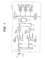
- Fig. 1 is a diagram illustrating the configuration of a protective relay apparatus comprising a protection/instrumentation control unit 3 and a current transformer according the embodiment of the present invention.
- a detection signal of a current or a voltage is inputted to a transformer input circuit from a main circuit 1.
- This transformer input circuit is usually configured of a transformer 2, an auxiliary transformer 4, a filter circuit 5, operational amplifiers 71 and 72, sample holding circuits 81 and 82, a multiplexer 9, and an analog/digital converter (A/D converter) 10 for converting an analog signal into a digital signal.
- the transformer input circuit is simply referred to as an input circuit.
- the input circuit allows an analog current or voltage detection signal to be finally inputted to a control circuit as a digital signal.
- the current or voltage detection signals inputted by the transformer 2, which are transmitted from the main circuit 1, are inputted to the auxiliary transformer 4, and thereafter are converted to a suitable level.
- These level-converted detection signals after being cleared by the filter circuit 5 of harmonics unnecessary for arithmetic operation for protection and instrumentation, are inputted to the operational amplifiers 71 and 72 for converting current signals into voltage signals.
- the detection signals delivered from the operational amplifiers 71 and 72 are sampled at prescribed intervals of time and held for a prescribed length of time by the sample holding circuits 81 and 82.
- the multiplexer 9 outputs what results from selective switching of these analog values inputted by the sample holding circuits 81 and 82 at prescribed intervals of time.
- a processing unit MPU (hereinafter, referred to as an MPU) 11 carries out protection/instrumentation control by processing the digital signals resulting from conversion by the A/D converter 10.
- a display section 12 displays the instrumentation result of processing by the MPU 11 by using various display equipment. According to the embodiment, the display section 12 comprises a seven-segment LED/LCD display and a pilot lamp indicating a status thereof as display means.
- the MPU 11 determines whether or not the result surpasses a prescribed value, for example, a current larger than the detectable range of the protection and instrumentation shown in Fig. 5, and, if it does, outputs a tripping instruction to a circuit breaker 15 via an output circuit 13, thus switching on/off the main circuit 1.
- a prescribed value for example, a current larger than the detectable range of the protection and instrumentation shown in Fig. 5, and, if it does, outputs a tripping instruction to a circuit breaker 15 via an output circuit 13, thus switching on/off the main circuit 1.
- Fig. 2 illustrates the configuration of a power switchboard 16 having the protective relay apparatus of the present invention, in which two sets of the configuration of the transformer and the protective relay apparatus comprising the protection/instrumentation control unit as shown in Fig. 1 are arranged, according to the embodiment of the present invention.
- Voltage and current information from main circuits 28 and 29 are inputted to protection/instrumentation control units 31 and 32 via transformers 21 and 22.
- Circuit breakers 51 and 52 switches on/off the main circuits 28 and 29 in response to instructions from the protection/instrumentation control units 31 and 32.
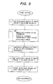
- Fig. 3 is a chart of a flow until the detectable ranges of the input circuits containing operational amplifiers 71 and 72 shown in Fig. 1 are derived and set according to the embodiment of the present invention.
- Fig. 5 is a logarithmic graph showing the relationship of detectable errors to an instrumented amperage by introducing, into the arithmetic expression, which will be described later, parameters obtained in accordance with the flow of Fig. 3 including the detectable ranges of the input circuits, according to the embodiment, in which the abscissa designates an amperage and the ordinate designates an error.
- the graph shown in Fig. 5 is used for checking whether characteristics derived from the arithmetic expression, which will be described later, are within the tolerable errors of the instrumentation range or within the tolerable errors of the protection range.
- Line (a) in graph of Fig. 5 represents conversion of the tolerance of the instrumentation range into operational value errors when a rated primary value of a 600A-type multi-current transformer is 40A.
- Line (a) is used as the reference for determination, and the error curve should not be above line (a) in the instrumentation area.
- Line (b) in graph of Fig. 5 represents conversion of the tolerance of the instrumentation range when the rated primary value of the 600A-type multi-current transformer is 600A.
- Line (b) is used as the reference for determination, and the error curve should not be above line (b) in the instrumentation area.
- the error curve should be not above the tolerance detectable error of 5% within the overall of the instrumentation and protection ranges as shown in Fig. 5.
- Line (c) in graph of Fig. 5 represents an error curve of the input circuit containing the operational amplifier 71 compatible with detection of a low current, which is obtained by the following arithmetic expression.
- Line (d) in graph of Fig. 5 represents an error curve of the input circuit containing the operational amplifier 72 compatible with detection of a high current, which is obtained by the following arithmetic expression.
- step (a) a value with a margin for the maximum value of detected currents out of the required detectable range of protection and instrumentation is within the detectable range of the input circuit B including the operational amplifier 72 (compatible with high current detection).
- an upper limit value of the detectable range is set to be 26. 4 [Arms].
- step (b) a partial voltage value inputted to the operational amplifier 72, gain of the operational amplifier 72, the resolving power of the A/D converter 10, etc. are set within the range of the tolerance detectable error (b) in Fig. 5.
- step (c) by substituting the setpoints in steps
- an input circuit A detects current values which are equal to or less than the lower limit value of approximately 0.1 [Arms].
- An upper limit value within the detectable current range of the input circuit A is 0.33 [Arms] with tolerance, much greater than the current value of approximately 0.1 [Arms] obtained in the step (c). That is, the detectable current range of the input circuit A is overlapped to that of the input circuit B.
- step (e) the detectable current ranges of the input circuits A and B figured out in steps (a) and (d) are stored into the memory 14.
- the MPU 11 performs the control and determination by referring to the detectable ranges while switching the outputs based on the input current and voltage values.
- the tolerances of lines (a) and (b) in Fig. 5 are satisfied within the instrumental range of 0.0005 to approximately 1.5 [Arms].
- the tolerance range of 5% is satisfied within the protection range of approximately 0.02 to 26.4 [Arms].
- the memory 14 stores therein the detected current values 0.0005, 0.33, and 26.4 [Arms] to switch the outputs of the input circuits A and B at 0.33 [Arms], shown in Fig. 5, and the input circuits A and B instrument the current values in accordance with the change in the detected current values.
- Line (e) in Fig. 5 shows the protection and instrumentation within the overall ranges of the instrumentation and protection.
- the ranges of the instrumentation and the protection are divided based on the detected result, to cover the instrumentation current range and reduce the instrumentation errors as much as possible, thus performing the instrumentation and the control at high accuracy.
- the current transformer having several kinds of primary rated current ratios can be achieved.
- the detectable current range of the 600A-type multi-current transformer is included in the error tolerance required within the detectable current range of protection and instrumentation, it can be confirmed that the performance requirements are satisfied. Therefore these detectable ranges are stored into the memory 14 as the setting values. The individual usage of the input circuits A and B for the protection and instrumentation is permitted, while holding the instrumentation accuracy depending on the amperage [Arms] as target.
- Lines (a) to (e) in Fig. 5 can be displayed by display means provided for the display section 12, and be displayed by an external personal computer connectable via a communication port.
- the error curve of the detected current and voltage can be derived by introducing the setpoints into the respective parameters of arithmetic expressions (1-16), which will be described later.
- the parameters to be set and the arithmetic operating steps are given below.
- the input circuit of the current transformer is supposed to be a two-input type, having the operational amplifiers 71 and 72 differing in gain characteristics from each other (range A compatible with detection of a minutely narrow range and range B compatible with detection of an extensive range).
- the operational amplifier 72 has gain characteristics compatible with wide range detection permitting detection in a wide varying range of a current
- the operational amplifier 71 has gain characteristics compatible with narrow range detection permitting detection in a narrow varying range of a current.
- Line (a) is a graph representing conversion of the tolerance of the instrumentation range when the rated primary value of the 600A-type multi-current transformer is 40A. Line (a) is used as the reference for judgment, and the error curve should not be above line (a) in the instrumentation area.
- Line (b) is a graph representing conversion of the tolerance of the instrumentation range when the rated primary value of the 600A-type multi-current transformer is 600A. Line (b) is used as the reference for judgment, and the error curve should not be above line (b) in the instrumentation area.
- Line (c) is the result of the following setting of the parameters of the arithmetic expressions (1-16) on the error curve of range A.
- Line (d) is the result of the following setting of the parameters of the arithmetic expressions (1-16) on the error curve of range B.
- Fig. 4 shows an example of waveform obtained by sampling (at an electrical angle of 30°) a current waveform (in analog values) delivered from the current transformer with the sample holding circuits 81 and 82. At the time of sampling, any error of the current transformer input circuit may come in. The worst case is an instance in which such an error as shown in Fig. 4 arises over a full period of the current waveform.
- Ie' 1 12 ⁇ ( i 0 + A ) 2 +( i 1 + A ) 2 + ⁇ +( i 5 + A ) 2 +( i 6 -A ) 2 +( i 7 -A ) 2 + ⁇ +( i 11 -A ) 2 ⁇
- Ie ' 1 12 ⁇ ( i 2 0 +2 Ai 0 + A 2 )+ ⁇ +( i 2 5 +2 Ai 5 + A 2 )+( i 2 6 -2 Ai 6 + A 2 )+ ⁇ +(i 2 11 -2 Ai 11 + A 2 ) ⁇
- Ie' 1 12 ⁇ ( i 2 0 + i 2 1 + ⁇ + i 2 11 )+ 2 A ( i 0 + i 1 + i 2 + i 3 + i 4 + i 5 - i 6 - i 7 - i 8 - i 9
- Expression (1-10) is substituted into Expression (1-9) to give: Ie' 2 -Ie 2 - A 3 ( i 0 + i 1 + i 2 + i 3 + i 4 + i 5 )+ A 2
- lines (c) and (d) in the graph of Fig. 5 can be obtained by inputting the instrumentation conditions of the input circuits A and B in the embodiment of the present invention.
- Ie' 1 6 ⁇ ( i 0 + A ) 2 + ( i 1 + A ) 2 + ⁇ +( i 5 + A ) 2 ⁇
- Ie' 1 6 ⁇ ( i 2 0 +2 Ai 0 + A 2 )+ ⁇ +( i 2 5 + 2 Ai 5 + A 2 ) ⁇
- the full scale setpoint can be represented by Expression (2-16).
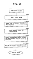
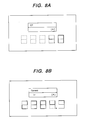
- Fig. 6 is a chart of a flow until setting the setting values, and Figs. 7A and 8B show display statuses of Fig. 6. A setting method of the setting values will be described with reference to Figs. 6 to 8.
- step S001 the protective relay apparatus shifts to a mode for setting the setting values of the input circuits A and B (hereinafter, simply referred to as a set mode) by using a switch (not shown) provided for the input section 52.
- a switch not shown
- the MPU 11 recognizes a standby mode for inputting the setting values.
- Fig. 7A shows a display screen after shifting to the set mode.
- the display section 12 comprises a 7-segment LED having an LCD display section provided at the top thereof which indicates the set mode at the present.
- step S002 for the purpose of inputting the type of a general wide-range transformer to be used by the input circuits A and B, the protective relay apparatus status shifts to a mode for inputting the type of the transformer by using an input switch (not shown).
- Fig. 7B shows a display screen for inputting the corresponding type.
- the 600A-type multi-current transformer is shared with the input circuits A and B.
- step S003 similarly to step S002, the protective relay apparatus shifts to a mode for inputting a primary value of the transformer, whereupon the primary value is inputted.
- Fig. 8A shows a display screen for inputting the primary value.
- the primary value of the transformer is inputted by using a keyboard arranged to the input section 52, alternatively, by using the switch arranged to the input section 52 when the primary value is predetermined.
- step S004 after completing the operation for setting the conditions of the setting values, the protective relay apparatus is reset to make the setting values effective.
- the MPU 11 reads the setting values stored in the memory 14, and sets the detectable ranges, as the setting values, which are used as instrumentation and protective areas of the input circuits A and B, in accordance with the above arithmetic expressions.
- step S005 the SET mode returns to a normal operating mode (mode for protection, instrumentation, and monitoring).
- Fig. 8B shows a display screen of the normal operating mode.
- step S006 the operation in the set mode ends.
- the operation of the protective relay apparatus can be detected with high accuracy even when the general wide-range transformer is used.
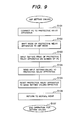
- Fig. 9 shows a chart of a flow until the setting values are set
- Figs. 10 to 14 show the configuration of the protective relay apparatus in Fig. 9.
- the setting method of the setting values will be described with reference to Figs. 10 to 14.
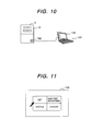
- step S101 a general personal computer (external PC) 152 is connected by using a communication port 182 attached to the protective relay apparatus, as shown in Fig. 10.
- the setting value information stored in the memory 14 can be inputted by the external PC 152.
- step S102 the protective relay apparatus shifts to the mode for setting the setting values by key operation.
- the mode of the protective relay apparatus shifts by using a keyboard (not shown) or a switch (not shown) arranged to the input section 52 in the protective relay apparatus, alternatively by using a key (not shown) of the personal computer 152.
- step S103 a mouse selects a set icon out of icons indicated on the screen of the personal computer 152 shown in Fig. 11, thus shifting to the set mode for inputting the setting values.
- data which indicates that the input circuits A and B use the 600A-type multi-current transformer, as a 600A-type wide-range transformer, for general-purpose use and the primary value of the 600A-type multi-current transformer is 40 [Arms], is inputted on the screen of the personal computer 152 shown in Fig. 12.
- step S104 the inputted setting-values are transmitted in a lump to the memory 14 of the protective relay apparatus by click of a send icon displayed on the screen.
- step S105 after completing the sending of the setting values, a reset icon displayed on the screen, for making the setting values effective is clicked, thus resetting the protective relay apparatus.
- the MPU 11 reads the conditions of the setting values, which are stored in the memory 14, and sets the detectable ranges of the input circuits A and B by calculation based on the above-stated arithmetic expressions.
- step S106 the protective relay apparatus is reset from the set mode to the normal operating mode for protection/instrumentation control.
- the above-mentioned operations are performed at least once, thereby setting the conditions of the setting values for the input circuits A and B, as setting targets, which share the wide-range transformer for general purpose.
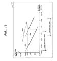
- Figs. 13 and 14 show graphs for checking to see if the required detection accuracy for protection and instrumentation elements is satisfied within the detectable range set to the input circuits A and B at the switching point of the input circuits A and B.
- Lines in the graphs of Figs. 13 and 14 are calculated by the MPU 11 or the personal computer 152 and are displayed on the screen of the LCD provided for the personal computer 152 or the display section 12.
- lines can be displayed through the input section 52 and the external PC 152.
- Fig. 13 shows a graph when the CT primary rated amperage is 600A.
- a line 601 is figured out by converting a tolerance between the instrumentation ranges of the effective amperage corresponding to the CT primary rated amperage 600A into an operating value error.
- error curves of the input circuits A and B should exist below the line 601.
- a horizontal dotted line 602 is a reference line indicating 5% as a reference satisfied by the protection element. In the protection area, the error curves of the input circuits A and B should exist below the line 602.
- a line 603 shows an error curve within the instrumentation range of the input circuit A.
- a line 604 shows an error curve within the instrumentation range of the input circuit B.
- the setting values of the input circuits A and B are determined along a bold line as a condition obtained by combining the lines 603 and 604.
- the determined setting values of the input circuits A and B satisfy the conditions of the lines 601 and 602.
- the input circuit A detects the effective amperages 0.001 to 0.33 [Arms]
- the switching point from the input circuit A to the input circuit B is set at the effective amperage 0.33 [Arms]
- the instrumentation for the effective amperage equal to or more than 0.33 [Arms] is performed by using the input circuit B.
- the input circuit B detects the effective amperages 0.33 to 26.4 [Arms].
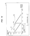
- Fig. 14 shows a graph when the CT primary rated amperage is 40A.
- a line 621 is figured out by converting a tolerance between the instrumentation ranges of the effective amperages corresponding to the CT primary rated amperage 40A into an operating-value error.
- error curves of the input circuits A and B should exist below the line of the line 621.
- a horizontal dotted line 622 is a reference line indicating 5% as a reference satisfied by the protection element. In the protection area, error curves of the input circuits A and B should exist below the line 622.
- a line 623 shows an error curve within the instrumentation range of the input circuit A.
- a line 624 shows an error curve within the instrumentation range of the input circuit B.
- a absolute condition is that a bold line obtained by combining the lines 623 and 624 satisfies the lines 621 and 622.
- the detectable ranges of the setting values of the input circuits A and B are determined along the bold line as the condition obtained by combining the lines 623 and 624.
- the determined setting values of the input circuits A and B satisfy the conditions of the graphs 601 and 602.
- the input circuit A detects the effective amperages 0.0004 to 0.03 [Arms]
- the switching point from the input circuit A to the input circuit B is set at the effective amperage 0.03 [Arms]
- the instrumentation for the effective amperage equal to or more than 0.03 [Arms] is performed by using the input circuit B.
- the input circuit B detects the effective amperages 0.03 to 7.0 [Arms].
- lines 621 to 624 can be displayed through the input section 52 or the personal computer 152, thus confirming whether or not the current setting values or new setting values of the input circuits A and B are correctly set.
- the setting values of the input circuits are displayed by using the graphs according to the embodiment of the present invention, the setting values can be displayed in a table format.
- the relationship between any error of the transformer input circuit and full scale setting is made clear by the arithmetic expressions (1-16).
- compatibility with a transformer having several kinds of primary rated current ratios or one kind of primary rated voltage ratio can be achieved by adjusting the parameters of the arithmetic expressions, it is capable of setting the detectable errors of the input circuits to be equal to or less than the reference detectable error.
- the protective relay apparatus or the power switchboard by displaying the setting values of the input circuits so that an operator can apparently understand them. Therefore, the setting values of the input circuits can be easily set and checked.
Landscapes
- Emergency Protection Circuit Devices (AREA)
- Measurement Of Current Or Voltage (AREA)
Applications Claiming Priority (2)
| Application Number | Priority Date | Filing Date | Title |
|---|---|---|---|
| JP2001056995 | 2001-03-01 | ||
| JP2001056995 | 2001-03-01 |
Publications (3)
| Publication Number | Publication Date |
|---|---|
| EP1237248A2 true EP1237248A2 (de) | 2002-09-04 |
| EP1237248A3 EP1237248A3 (de) | 2006-02-22 |
| EP1237248B1 EP1237248B1 (de) | 2015-11-04 |
Family
ID=18916938
Family Applications (1)
| Application Number | Title | Priority Date | Filing Date |
|---|---|---|---|
| EP01121009.3A Expired - Lifetime EP1237248B1 (de) | 2001-03-01 | 2001-08-31 | Schutzrelais |
Country Status (3)
| Country | Link |
|---|---|
| US (2) | US6678136B2 (de) |
| EP (1) | EP1237248B1 (de) |
| TW (1) | TW533642B (de) |
Cited By (2)
| Publication number | Priority date | Publication date | Assignee | Title |
|---|---|---|---|---|
| EP1677402A3 (de) * | 2004-11-17 | 2006-07-12 | Siemens Aktiengesellschaft | Verfahren und Schaltungsanordnung zur Verstärkung der Eingangssignale eines elektronischen Überstromauslösers von Niederspannungs-Leistungsschaltern |
| RU2463693C2 (ru) * | 2008-02-15 | 2012-10-10 | Абб Текнолоджи Лтд | Автономное самозапитывающееся реле с числовым управлением |
Families Citing this family (4)
| Publication number | Priority date | Publication date | Assignee | Title |
|---|---|---|---|---|
| WO2013175846A1 (ja) * | 2012-05-21 | 2013-11-28 | 三菱電機株式会社 | 保護継電装置の動作試験システム |
| KR101649704B1 (ko) | 2015-07-28 | 2016-08-19 | 엘에스산전 주식회사 | 디지털 보호 계전기의 전원 감시장치 |
| WO2018211577A1 (ja) * | 2017-05-16 | 2018-11-22 | 三菱電機株式会社 | デジタルリレー |
| US10840012B2 (en) * | 2018-11-21 | 2020-11-17 | Eaton Intelligent Power Limited | Single input circuit for receiving output from a di/dt sensor or current transformer and circuit breaker including same |
Citations (1)
| Publication number | Priority date | Publication date | Assignee | Title |
|---|---|---|---|---|
| US6075368A (en) | 1995-03-10 | 2000-06-13 | Cooper Industries, Inc. | Method of improving fault current measurement accuracy on electronic reclosure control |
Family Cites Families (5)
| Publication number | Priority date | Publication date | Assignee | Title |
|---|---|---|---|---|
| US3815011A (en) * | 1973-03-30 | 1974-06-04 | Gen Electric | Current transformer terminated by active load elements for providing phase-inverted signals |
| US3995210A (en) * | 1974-11-06 | 1976-11-30 | General Electric Company | Variable gain electronic current transformer |
| US4259706A (en) * | 1978-10-06 | 1981-03-31 | Gould Inc. | Solid state relay |
| US4847723A (en) * | 1988-05-20 | 1989-07-11 | Westinghouse Electric Corp. | Volt-per-hertz protection apparatus |
| JP2677722B2 (ja) * | 1991-07-05 | 1997-11-17 | 株式会社東芝 | ディジタル保護継電器 |
-
2001
- 2001-08-31 EP EP01121009.3A patent/EP1237248B1/de not_active Expired - Lifetime
- 2001-08-31 US US09/942,691 patent/US6678136B2/en not_active Expired - Lifetime
- 2001-08-31 TW TW090121670A patent/TW533642B/zh not_active IP Right Cessation
-
2002
- 2002-09-20 US US10/247,340 patent/US6683769B2/en not_active Expired - Lifetime
Patent Citations (1)
| Publication number | Priority date | Publication date | Assignee | Title |
|---|---|---|---|---|
| US6075368A (en) | 1995-03-10 | 2000-06-13 | Cooper Industries, Inc. | Method of improving fault current measurement accuracy on electronic reclosure control |
Cited By (2)
| Publication number | Priority date | Publication date | Assignee | Title |
|---|---|---|---|---|
| EP1677402A3 (de) * | 2004-11-17 | 2006-07-12 | Siemens Aktiengesellschaft | Verfahren und Schaltungsanordnung zur Verstärkung der Eingangssignale eines elektronischen Überstromauslösers von Niederspannungs-Leistungsschaltern |
| RU2463693C2 (ru) * | 2008-02-15 | 2012-10-10 | Абб Текнолоджи Лтд | Автономное самозапитывающееся реле с числовым управлением |
Also Published As
| Publication number | Publication date |
|---|---|
| TW533642B (en) | 2003-05-21 |
| US6678136B2 (en) | 2004-01-13 |
| EP1237248B1 (de) | 2015-11-04 |
| US20020159211A1 (en) | 2002-10-31 |
| US20030072114A1 (en) | 2003-04-17 |
| EP1237248A3 (de) | 2006-02-22 |
| US6683769B2 (en) | 2004-01-27 |
Similar Documents
| Publication | Publication Date | Title |
|---|---|---|
| US8217677B2 (en) | System and method for modulating a power supply in a relay test system | |
| JP5791796B2 (ja) | 保護継電装置の動作試験システム | |
| EP1237248A2 (de) | Schutzrelais | |
| JPS62110168A (ja) | デイジタル故障点標定装置 | |
| JPH09213542A (ja) | 負荷時タップ切換器の状態監視装置 | |
| AU695365B2 (en) | Electrical apparatus with wide dynamic range for monitoring and protecting electric power systems | |
| JP6456573B1 (ja) | 保護継電装置の特性試験システム | |
| JP7739417B2 (ja) | ガス絶縁サージアレスタおよびガス絶縁サージアレスタ監視システム | |
| JP4874480B2 (ja) | 回路遮断器の監視システム | |
| US8000933B1 (en) | Method and apparatus for showing data representative of the accuracy of operations of a high-voltage switchgear | |
| JP3892735B2 (ja) | 電気量測定方法及び装置、並びに保護継電器 | |
| CN216595345U (zh) | 一种抗干扰测试系统 | |
| KR101705965B1 (ko) | 이중 표시장치를 구비하는 전력 관리 보호 장치 | |
| US20240006868A1 (en) | Method and System for Detecting Phenomenon in Electrical Power Network | |
| CN202885960U (zh) | 一种用于自动轨道衡上的传感器监控、检测系统 | |
| KR200360940Y1 (ko) | 저항식 변성기를 구비한 저항식 복합계전기 | |
| JPH0413978A (ja) | 電流計測方法および装置ならびに開閉装置遮断部寿命診断装置 | |
| JP2012135150A (ja) | ディジタル保護継電装置 | |
| JP2755697B2 (ja) | 保護継電装置 | |
| JP4103789B2 (ja) | 保護制御装置 | |
| KR930011359A (ko) | 디지탈 배전선로 보호시스템 | |
| JP2002281615A (ja) | 配電盤の監視保護装置 | |
| JP2585211B2 (ja) | 保護継電装置 | |
| JPS6258209B2 (de) | ||
| JP2014150693A (ja) | ディジタル形保護制御装置 |
Legal Events
| Date | Code | Title | Description |
|---|---|---|---|
| PUAI | Public reference made under article 153(3) epc to a published international application that has entered the european phase |
Free format text: ORIGINAL CODE: 0009012 |
|
| AK | Designated contracting states |
Kind code of ref document: A2 Designated state(s): AT BE CH CY DE DK ES FI FR GB GR IE IT LI LU MC NL PT SE TR |
|
| AX | Request for extension of the european patent |
Free format text: AL;LT;LV;MK;RO;SI |
|
| PUAL | Search report despatched |
Free format text: ORIGINAL CODE: 0009013 |
|
| AK | Designated contracting states |
Kind code of ref document: A3 Designated state(s): AT BE CH CY DE DK ES FI FR GB GR IE IT LI LU MC NL PT SE TR |
|
| AX | Request for extension of the european patent |
Extension state: AL LT LV MK RO SI |
|
| 17P | Request for examination filed |
Effective date: 20060331 |
|
| AKX | Designation fees paid |
Designated state(s): DE FR |
|
| 17Q | First examination report despatched |
Effective date: 20110705 |
|
| REG | Reference to a national code |
Ref country code: DE Ref legal event code: R079 Ref document number: 60149649 Country of ref document: DE Free format text: PREVIOUS MAIN CLASS: H02H0003000000 Ipc: H02H0001000000 |
|
| GRAP | Despatch of communication of intention to grant a patent |
Free format text: ORIGINAL CODE: EPIDOSNIGR1 |
|
| RIC1 | Information provided on ipc code assigned before grant |
Ipc: H02H 3/00 20060101ALI20150429BHEP Ipc: H02H 1/00 20060101AFI20150429BHEP |
|
| INTG | Intention to grant announced |
Effective date: 20150520 |
|
| GRAS | Grant fee paid |
Free format text: ORIGINAL CODE: EPIDOSNIGR3 |
|
| GRAA | (expected) grant |
Free format text: ORIGINAL CODE: 0009210 |
|
| AK | Designated contracting states |
Kind code of ref document: B1 Designated state(s): DE FR |
|
| REG | Reference to a national code |
Ref country code: DE Ref legal event code: R096 Ref document number: 60149649 Country of ref document: DE |
|
| REG | Reference to a national code |
Ref country code: DE Ref legal event code: R097 Ref document number: 60149649 Country of ref document: DE |
|
| PLBE | No opposition filed within time limit |
Free format text: ORIGINAL CODE: 0009261 |
|
| STAA | Information on the status of an ep patent application or granted ep patent |
Free format text: STATUS: NO OPPOSITION FILED WITHIN TIME LIMIT |
|
| 26N | No opposition filed |
Effective date: 20160805 |
|
| REG | Reference to a national code |
Ref country code: DE Ref legal event code: R119 Ref document number: 60149649 Country of ref document: DE |
|
| REG | Reference to a national code |
Ref country code: FR Ref legal event code: ST Effective date: 20170428 |
|
| PG25 | Lapsed in a contracting state [announced via postgrant information from national office to epo] |
Ref country code: FR Free format text: LAPSE BECAUSE OF NON-PAYMENT OF DUE FEES Effective date: 20160831 Ref country code: DE Free format text: LAPSE BECAUSE OF NON-PAYMENT OF DUE FEES Effective date: 20170301 |