EP1237226B1 - Verbesserungen in oder bezüglich elektrischer Steckverbinder - Google Patents
Verbesserungen in oder bezüglich elektrischer Steckverbinder Download PDFInfo
- Publication number
- EP1237226B1 EP1237226B1 EP01301442A EP01301442A EP1237226B1 EP 1237226 B1 EP1237226 B1 EP 1237226B1 EP 01301442 A EP01301442 A EP 01301442A EP 01301442 A EP01301442 A EP 01301442A EP 1237226 B1 EP1237226 B1 EP 1237226B1
- Authority
- EP
- European Patent Office
- Prior art keywords
- contact
- metal sleeve
- spring finger
- cable
- pin
- Prior art date
- Legal status (The legal status is an assumption and is not a legal conclusion. Google has not performed a legal analysis and makes no representation as to the accuracy of the status listed.)
- Expired - Lifetime
Links
- 239000004020 conductor Substances 0.000 claims abstract description 22
- 239000012212 insulator Substances 0.000 claims description 10
- 239000002184 metal Substances 0.000 claims description 10
- 229910052751 metal Inorganic materials 0.000 claims description 10
- 238000003780 insertion Methods 0.000 claims description 5
- 230000037431 insertion Effects 0.000 claims description 5
- 230000000717 retained effect Effects 0.000 claims description 3
- RYGMFSIKBFXOCR-UHFFFAOYSA-N Copper Chemical compound [Cu] RYGMFSIKBFXOCR-UHFFFAOYSA-N 0.000 description 2
- PXHVJJICTQNCMI-UHFFFAOYSA-N Nickel Chemical compound [Ni] PXHVJJICTQNCMI-UHFFFAOYSA-N 0.000 description 2
- 229910001369 Brass Inorganic materials 0.000 description 1
- 229910000906 Bronze Inorganic materials 0.000 description 1
- OAICVXFJPJFONN-UHFFFAOYSA-N Phosphorus Chemical compound [P] OAICVXFJPJFONN-UHFFFAOYSA-N 0.000 description 1
- 101700004678 SLIT3 Proteins 0.000 description 1
- 102100027339 Slit homolog 3 protein Human genes 0.000 description 1
- 230000005540 biological transmission Effects 0.000 description 1
- 239000010951 brass Substances 0.000 description 1
- 239000010974 bronze Substances 0.000 description 1
- KUNSUQLRTQLHQQ-UHFFFAOYSA-N copper tin Chemical compound [Cu].[Sn] KUNSUQLRTQLHQQ-UHFFFAOYSA-N 0.000 description 1
- 238000006073 displacement reaction Methods 0.000 description 1
- 239000012777 electrically insulating material Substances 0.000 description 1
- 239000000463 material Substances 0.000 description 1
- 238000012986 modification Methods 0.000 description 1
- 230000004048 modification Effects 0.000 description 1
- 229910052759 nickel Inorganic materials 0.000 description 1
- 238000005096 rolling process Methods 0.000 description 1
- 125000006850 spacer group Chemical group 0.000 description 1
- 230000007704 transition Effects 0.000 description 1
Images
Classifications
-
- H—ELECTRICITY
- H01—ELECTRIC ELEMENTS
- H01R—ELECTRICALLY-CONDUCTIVE CONNECTIONS; STRUCTURAL ASSOCIATIONS OF A PLURALITY OF MUTUALLY-INSULATED ELECTRICAL CONNECTING ELEMENTS; COUPLING DEVICES; CURRENT COLLECTORS
- H01R9/00—Structural associations of a plurality of mutually-insulated electrical connecting elements, e.g. terminal strips or terminal blocks; Terminals or binding posts mounted upon a base or in a case; Bases therefor
- H01R9/03—Connectors arranged to contact a plurality of the conductors of a multiconductor cable, e.g. tapping connections
- H01R9/05—Connectors arranged to contact a plurality of the conductors of a multiconductor cable, e.g. tapping connections for coaxial cables
-
- H—ELECTRICITY
- H01—ELECTRIC ELEMENTS
- H01R—ELECTRICALLY-CONDUCTIVE CONNECTIONS; STRUCTURAL ASSOCIATIONS OF A PLURALITY OF MUTUALLY-INSULATED ELECTRICAL CONNECTING ELEMENTS; COUPLING DEVICES; CURRENT COLLECTORS
- H01R4/00—Electrically-conductive connections between two or more conductive members in direct contact, i.e. touching one another; Means for effecting or maintaining such contact; Electrically-conductive connections having two or more spaced connecting locations for conductors and using contact members penetrating insulation
- H01R4/28—Clamped connections, spring connections
- H01R4/48—Clamped connections, spring connections utilising a spring, clip, or other resilient member
- H01R4/4809—Clamped connections, spring connections utilising a spring, clip, or other resilient member using a leaf spring to bias the conductor toward the busbar
- H01R4/4846—Busbar details
- H01R4/4848—Busbar integrally formed with the spring
-
- H—ELECTRICITY
- H01—ELECTRIC ELEMENTS
- H01R—ELECTRICALLY-CONDUCTIVE CONNECTIONS; STRUCTURAL ASSOCIATIONS OF A PLURALITY OF MUTUALLY-INSULATED ELECTRICAL CONNECTING ELEMENTS; COUPLING DEVICES; CURRENT COLLECTORS
- H01R4/00—Electrically-conductive connections between two or more conductive members in direct contact, i.e. touching one another; Means for effecting or maintaining such contact; Electrically-conductive connections having two or more spaced connecting locations for conductors and using contact members penetrating insulation
- H01R4/28—Clamped connections, spring connections
- H01R4/48—Clamped connections, spring connections utilising a spring, clip, or other resilient member
- H01R4/4809—Clamped connections, spring connections utilising a spring, clip, or other resilient member using a leaf spring to bias the conductor toward the busbar
- H01R4/48185—Clamped connections, spring connections utilising a spring, clip, or other resilient member using a leaf spring to bias the conductor toward the busbar adapted for axial insertion of a wire end
- H01R4/4819—Clamped connections, spring connections utilising a spring, clip, or other resilient member using a leaf spring to bias the conductor toward the busbar adapted for axial insertion of a wire end the spring shape allowing insertion of the conductor end when the spring is unbiased
- H01R4/4821—Single-blade spring
-
- H—ELECTRICITY
- H01—ELECTRIC ELEMENTS
- H01R—ELECTRICALLY-CONDUCTIVE CONNECTIONS; STRUCTURAL ASSOCIATIONS OF A PLURALITY OF MUTUALLY-INSULATED ELECTRICAL CONNECTING ELEMENTS; COUPLING DEVICES; CURRENT COLLECTORS
- H01R4/00—Electrically-conductive connections between two or more conductive members in direct contact, i.e. touching one another; Means for effecting or maintaining such contact; Electrically-conductive connections having two or more spaced connecting locations for conductors and using contact members penetrating insulation
- H01R4/28—Clamped connections, spring connections
- H01R4/48—Clamped connections, spring connections utilising a spring, clip, or other resilient member
- H01R4/4809—Clamped connections, spring connections utilising a spring, clip, or other resilient member using a leaf spring to bias the conductor toward the busbar
- H01R4/484—Spring housing details
Definitions
- This invention concerns improvements in electrical connectors, and relates more especially, but not exclusively, to co-axial connectors of the kind utilised for connecting the cables of television antennas to associated equipment.
- Hitherto known co-axial connectors of this kind generally comprise an outer cylindrical sleeve within which is supported a hollow centre pin via an insulating spacer.
- the outer cylindrical sleeve is secured within, or is integral with, a male threaded housing member that engages with a female threaded housing cap having a central aperture through which the co-axial cable can pass.
- a collapsible contact element that is placed around the braided conductor of the co-axial cable in order to provide an electrical connection between the latter and the outer cylindrical sleeve.
- the electrically insulated centre core of the cable is stripped to expose the centre conductor of the co-axial cable, which is normally a single strand of copper wire, and the latter is inserted within the hollow centre pin of the electrical connector.
- an object of the invention to provide an electrical connector that can be connected to an electrical cable in a simple manner whilst ensuring a reliable electrical contact between a wire conductor of the cable and a hollow pin contact of the connector.
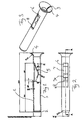
- a generally cylindrical contact pin is formed by rolling from sheet metal to the shape illustrated and is composed of suitable electrical contact material such as nickel plated brass or phosphor bronze.
- the dimensions of the pin correspond to those of a standard co-axial television cable connector and, typically, the pin would be of approximately 17.5mm in length and 2.4mm in external diameter.
- the cylindrical wall 1 of the contact is tapered inwardly at one end 2, in a conventional manner, and has a longitudinal slit 3 formed by the abutting edges of the rolled sheet from which the contact is formed.
- An opposite end of the contact has a trumpet shaped mouth 4 to facilitate insertion an electrical conductor and to retain the pin within an outer insulator as described below.
- an internally angled spring finger 5 is formed by severing a portion of the cylindrical wall 1 of the contact pin and folding this inwardly to the shape illustrated.
- the internally directed spring finger 5 has a shoulder portion 6 forming a transition between the cylindrical wall 1 of the contact pin and a flattened portion 7 that is angled inwardly relatively to the axis of the contact pin, for example at an angle of approximately 155°.
- a flattened end portion 7A of the spring finger 5 is angled away from the longitudinal axis of the contact, at an angle of, for example, 25°, to form an elbow in the contact finger 5 as shown in Fig. 1.
- the residual aperture left in the wall of the cylindrical contact terminates at a free edge in an outwardly angled lip 8, as can be seen from Figs. 1 and 3.
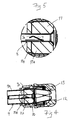
- a complete electrical connector incorporating the contact of Figs. 1 and 3 comprises a generally cylindrical metal sleeve 9 secured within a male screw threaded housing member 10 and having a portion 9A of wider diameter and a narrow portion 9B.
- An annular member 11 of electrically insulating material is located within the sleeve 9 and has a wider portion 11A fitting within the wider portion 9A of the conductor sleeve 9, and a narrow portion 11B fitting within the narrow portion 9B of the sleeve 9.
- the insulator 11 is located axially by means of a shoulder of the sleeve 9 between the wider and narrower portions 9A and 9B.
- the contact pin 1 is a push fit within a central aperture of the annular insulator 11, the lip 8 of the contact 1 serving as an abutment to snap engage with one end of the insulator 11 and the widened trumpet mouth 4 abutting against the other end. The contact pin 1 is thus retained therein against relative displacement, in use.
- the internal wall of the insulator 11 overlies the aperture in the wall of the contact pin 1, and thus presents the end 7A of the spring finger 5 from being displaced outwardly through the aperture in the wall 1 of the contact.
- the portion 7 of the spring finger 5 is firstly engaged by the wire conductor and displaced outwardly until the free end 7A contacts the internal surface of the insulator 11. Thereafter, upon further insertion of the conductor wire, the two angled portions 7,7A of the finger 5 are flexed relatively to one another in order to ensure firm contact between the spring finger 5 and the conductor wire.
- the cable After insertion of a central conductor of a coaxial cable into the contact pin, the cable is retained in place in conventional manner by securing a female threaded cap 12 on to the male threaded housing member 10, a collapsible contact member 13 providing an electrical connection between the outer conductor of the co-axial cable and the cylindrical sleeve 9 in a conventional manner that is well known to those skilled in the art.
Landscapes
- Coupling Device And Connection With Printed Circuit (AREA)
- Organic Insulating Materials (AREA)
Claims (4)
- Kontaktstiftanordnung für einen elektrischen Verbinder zur Verbindung mit einem elektrischen Kabel, umfassend eine im Wesentlichen zylindrische Metallhülse 1 zur Aufnahme eines zentralen Leiters eines elektrischen Kabels und einen ringförmigen Isolator 11, der koaxial zur genannten Metallhülse angeordnet ist, um diese Metallhülse (1) von einem äußeren Leiter (9), der koaxial mit ihr verläuft, zu beabstanden, wobei ein sich in Längsrichtung erstreckender Abschnitt der Wand der genannten Metallhülse (1) teilweise aufgetrennt ist, um eine Federlasche (5) zu bilden, mit einem Abschnitt 7, der nach innen gewinkelt und einem Abschnitt (7A), der nach außen gewinkelt ist, um einen Ellenbogen für einen Kontakt mit einem zentralen Leiter des elektrischen Kabels zu bilden, dadurch gekennzeichnet, dass der genannte ringförmige Isolator (11) so um die genannte Metallhülse (1) angeordnet ist, dass er einen Anschlag für einen Eingriff des genannten nach außen gerichteten gewinkelten Abschnitts (7A) der Federlasche beim Einsetzen eines Kabelleiters in die zylindrische metallische Hülse (1) bildet, wodurch die genannte Federlasche (5) in festem Kontakt mit dem Kabelleiter gehaltert wird.
- Kontaktstiftanordnung nach Anspruch 1, wobei eine freie Kante (8) einer Ausnehmung in der Wand der genannten metallischen Hülse (1), die durch das Heraustrennen der genannten Federlasche (5) gebildet ist, mit einer nach außen gerichteten Abwinklung versehen ist, um die Metallhülse (1) durch eine Schnappverbindung innerhalb des genannten ringförmigen Isolators zu haltern.
- Kontaktstiftanordnung nach Anspruch 2, wobei der genannte ringförmige Isolator zwischen der genannten nach außen gewinkelten freien Kante (8) und einem erweiterten Mundstück der genannten zylindrischen Metallhülse (1) gehaltert ist.
- Kontaktstiftanordnung nach einem der Ansprüche 1 bis 3, wobei dieser Stiftkontakt in einem koaxialen Kabelverbinder zur Bildung des Zentratstifts angeordnet ist.
Priority Applications (3)
| Application Number | Priority Date | Filing Date | Title |
|---|---|---|---|
| AT01301442T ATE278254T1 (de) | 2001-02-19 | 2001-02-19 | Verbesserungen in oder bezüglich elektrischer steckverbinder |
| DE60105965T DE60105965T2 (de) | 2001-02-19 | 2001-02-19 | Verbesserungen in oder bezüglich elektrischer Steckverbindungen |
| EP01301442A EP1237226B1 (de) | 2001-02-19 | 2001-02-19 | Verbesserungen in oder bezüglich elektrischer Steckverbinder |
Applications Claiming Priority (1)
| Application Number | Priority Date | Filing Date | Title |
|---|---|---|---|
| EP01301442A EP1237226B1 (de) | 2001-02-19 | 2001-02-19 | Verbesserungen in oder bezüglich elektrischer Steckverbinder |
Publications (2)
| Publication Number | Publication Date |
|---|---|
| EP1237226A1 EP1237226A1 (de) | 2002-09-04 |
| EP1237226B1 true EP1237226B1 (de) | 2004-09-29 |
Family
ID=8181723
Family Applications (1)
| Application Number | Title | Priority Date | Filing Date |
|---|---|---|---|
| EP01301442A Expired - Lifetime EP1237226B1 (de) | 2001-02-19 | 2001-02-19 | Verbesserungen in oder bezüglich elektrischer Steckverbinder |
Country Status (3)
| Country | Link |
|---|---|
| EP (1) | EP1237226B1 (de) |
| AT (1) | ATE278254T1 (de) |
| DE (1) | DE60105965T2 (de) |
Families Citing this family (3)
| Publication number | Priority date | Publication date | Assignee | Title |
|---|---|---|---|---|
| DE10317867B3 (de) * | 2003-04-17 | 2004-10-07 | Amphenol-Tuchel Electronics Gmbh | Kontaktvorrichtung |
| GB2423422B (en) * | 2004-02-21 | 2007-01-03 | Hitesh Dhanji Patel | Electrical connections and connectors |
| CN105870649B (zh) * | 2016-05-25 | 2019-02-26 | 国网河南省电力公司济源供电公司 | 一种安全型针状快速连接头 |
Family Cites Families (3)
| Publication number | Priority date | Publication date | Assignee | Title |
|---|---|---|---|---|
| US5061207A (en) * | 1990-09-27 | 1991-10-29 | Gte Products Corporation | Connector for a shielded coaxial cable |
| US5474470A (en) * | 1994-03-30 | 1995-12-12 | Itt Corporation | Compensated interface coaxial connector apparatus |
| US5865654A (en) * | 1997-01-23 | 1999-02-02 | Raychem Corporation | Coaxial cable connector |
-
2001
- 2001-02-19 AT AT01301442T patent/ATE278254T1/de not_active IP Right Cessation
- 2001-02-19 DE DE60105965T patent/DE60105965T2/de not_active Expired - Fee Related
- 2001-02-19 EP EP01301442A patent/EP1237226B1/de not_active Expired - Lifetime
Also Published As
| Publication number | Publication date |
|---|---|
| DE60105965T2 (de) | 2005-10-13 |
| ATE278254T1 (de) | 2004-10-15 |
| DE60105965D1 (de) | 2004-11-04 |
| EP1237226A1 (de) | 2002-09-04 |
Similar Documents
| Publication | Publication Date | Title |
|---|---|---|
| US4339166A (en) | Connector | |
| US7070463B2 (en) | Waterproof relay connector | |
| US4688876A (en) | Connector for coaxial cable | |
| EP0099633B1 (de) | Steckerdose eines Koaxialverbinders | |
| US4619496A (en) | Coaxial plug and jack connectors | |
| US5066248A (en) | Manually installable coaxial cable connector | |
| US4453796A (en) | Coaxial connector plug | |
| US7753725B2 (en) | Coaxial angle connector | |
| US8016615B2 (en) | Phone plug connector device | |
| EP0294419B1 (de) | Einpressgefertigter flachbausteckverbinder | |
| US5496968A (en) | Shielded cable connecting terminal | |
| US4690481A (en) | Coaxial coupling | |
| GB2079549A (en) | Coaxial cable connector | |
| EP1115177A3 (de) | Elektrischer Steckverbinder | |
| GB2459886A (en) | Shielded electrical connector having resiliently urging means making electrical connection between cable shield and connector | |
| US5536184A (en) | Connector assembly | |
| US4076367A (en) | Solderless connector | |
| US7001220B2 (en) | Coaxial plug-and-socket connection | |
| GB2139018A (en) | Coaxial plug and jack connectors | |
| US4138188A (en) | Coaxial cable plug with center conductor as center contact | |
| US20030224658A1 (en) | Electrical connector | |
| US4861284A (en) | Switch activating plug for a coaxial connector | |
| EP1191655B1 (de) | Krimpfreier Zugentlastungsabschluss für Koaxialkabel | |
| EP1237226B1 (de) | Verbesserungen in oder bezüglich elektrischer Steckverbinder | |
| JP2019087517A (ja) | 電気コネクタ |
Legal Events
| Date | Code | Title | Description |
|---|---|---|---|
| PUAI | Public reference made under article 153(3) epc to a published international application that has entered the european phase |
Free format text: ORIGINAL CODE: 0009012 |
|
| AK | Designated contracting states |
Kind code of ref document: A1 Designated state(s): AT BE CH CY DE DK ES FI FR GB GR IE IT LI LU MC NL PT SE TR |
|
| AX | Request for extension of the european patent |
Free format text: AL;LT;LV;MK;RO;SI |
|
| 17P | Request for examination filed |
Effective date: 20030304 |
|
| AKX | Designation fees paid |
Designated state(s): AT BE CH CY DE DK ES FI FR GB GR IE IT LI LU MC NL PT SE TR |
|
| 17Q | First examination report despatched |
Effective date: 20030724 |
|
| GRAP | Despatch of communication of intention to grant a patent |
Free format text: ORIGINAL CODE: EPIDOSNIGR1 |
|
| GRAS | Grant fee paid |
Free format text: ORIGINAL CODE: EPIDOSNIGR3 |
|
| GRAA | (expected) grant |
Free format text: ORIGINAL CODE: 0009210 |
|
| AK | Designated contracting states |
Kind code of ref document: B1 Designated state(s): AT BE CH CY DE DK ES FI FR GB GR IE IT LI LU MC NL PT SE TR |
|
| PG25 | Lapsed in a contracting state [announced via postgrant information from national office to epo] |
Ref country code: IT Free format text: LAPSE BECAUSE OF FAILURE TO SUBMIT A TRANSLATION OF THE DESCRIPTION OR TO PAY THE FEE WITHIN THE PRESCRIBED TIME-LIMIT;WARNING: LAPSES OF ITALIAN PATENTS WITH EFFECTIVE DATE BEFORE 2007 MAY HAVE OCCURRED AT ANY TIME BEFORE 2007. THE CORRECT EFFECTIVE DATE MAY BE DIFFERENT FROM THE ONE RECORDED. Effective date: 20040929 Ref country code: TR Free format text: LAPSE BECAUSE OF FAILURE TO SUBMIT A TRANSLATION OF THE DESCRIPTION OR TO PAY THE FEE WITHIN THE PRESCRIBED TIME-LIMIT Effective date: 20040929 Ref country code: AT Free format text: LAPSE BECAUSE OF FAILURE TO SUBMIT A TRANSLATION OF THE DESCRIPTION OR TO PAY THE FEE WITHIN THE PRESCRIBED TIME-LIMIT Effective date: 20040929 Ref country code: FI Free format text: LAPSE BECAUSE OF FAILURE TO SUBMIT A TRANSLATION OF THE DESCRIPTION OR TO PAY THE FEE WITHIN THE PRESCRIBED TIME-LIMIT Effective date: 20040929 Ref country code: LI Free format text: LAPSE BECAUSE OF FAILURE TO SUBMIT A TRANSLATION OF THE DESCRIPTION OR TO PAY THE FEE WITHIN THE PRESCRIBED TIME-LIMIT Effective date: 20040929 Ref country code: BE Free format text: LAPSE BECAUSE OF FAILURE TO SUBMIT A TRANSLATION OF THE DESCRIPTION OR TO PAY THE FEE WITHIN THE PRESCRIBED TIME-LIMIT Effective date: 20040929 Ref country code: CH Free format text: LAPSE BECAUSE OF FAILURE TO SUBMIT A TRANSLATION OF THE DESCRIPTION OR TO PAY THE FEE WITHIN THE PRESCRIBED TIME-LIMIT Effective date: 20040929 |
|
| REG | Reference to a national code |
Ref country code: GB Ref legal event code: FG4D |
|
| REG | Reference to a national code |
Ref country code: CH Ref legal event code: EP |
|
| REG | Reference to a national code |
Ref country code: IE Ref legal event code: FG4D |
|
| REF | Corresponds to: |
Ref document number: 60105965 Country of ref document: DE Date of ref document: 20041104 Kind code of ref document: P |
|
| PG25 | Lapsed in a contracting state [announced via postgrant information from national office to epo] |
Ref country code: SE Free format text: LAPSE BECAUSE OF FAILURE TO SUBMIT A TRANSLATION OF THE DESCRIPTION OR TO PAY THE FEE WITHIN THE PRESCRIBED TIME-LIMIT Effective date: 20041229 Ref country code: DK Free format text: LAPSE BECAUSE OF FAILURE TO SUBMIT A TRANSLATION OF THE DESCRIPTION OR TO PAY THE FEE WITHIN THE PRESCRIBED TIME-LIMIT Effective date: 20041229 Ref country code: GR Free format text: LAPSE BECAUSE OF FAILURE TO SUBMIT A TRANSLATION OF THE DESCRIPTION OR TO PAY THE FEE WITHIN THE PRESCRIBED TIME-LIMIT Effective date: 20041229 |
|
| PG25 | Lapsed in a contracting state [announced via postgrant information from national office to epo] |
Ref country code: ES Free format text: LAPSE BECAUSE OF FAILURE TO SUBMIT A TRANSLATION OF THE DESCRIPTION OR TO PAY THE FEE WITHIN THE PRESCRIBED TIME-LIMIT Effective date: 20050109 |
|
| PG25 | Lapsed in a contracting state [announced via postgrant information from national office to epo] |
Ref country code: CY Free format text: LAPSE BECAUSE OF FAILURE TO SUBMIT A TRANSLATION OF THE DESCRIPTION OR TO PAY THE FEE WITHIN THE PRESCRIBED TIME-LIMIT Effective date: 20050219 Ref country code: LU Free format text: LAPSE BECAUSE OF NON-PAYMENT OF DUE FEES Effective date: 20050219 |
|
| PG25 | Lapsed in a contracting state [announced via postgrant information from national office to epo] |
Ref country code: IE Free format text: LAPSE BECAUSE OF NON-PAYMENT OF DUE FEES Effective date: 20050221 |
|
| PG25 | Lapsed in a contracting state [announced via postgrant information from national office to epo] |
Ref country code: MC Free format text: LAPSE BECAUSE OF NON-PAYMENT OF DUE FEES Effective date: 20050228 |
|
| REG | Reference to a national code |
Ref country code: CH Ref legal event code: PL |
|
| PLBE | No opposition filed within time limit |
Free format text: ORIGINAL CODE: 0009261 |
|
| STAA | Information on the status of an ep patent application or granted ep patent |
Free format text: STATUS: NO OPPOSITION FILED WITHIN TIME LIMIT |
|
| PG25 | Lapsed in a contracting state [announced via postgrant information from national office to epo] |
Ref country code: DE Free format text: LAPSE BECAUSE OF NON-PAYMENT OF DUE FEES Effective date: 20050901 Ref country code: NL Free format text: LAPSE BECAUSE OF NON-PAYMENT OF DUE FEES Effective date: 20050901 |
|
| ET | Fr: translation filed | ||
| 26N | No opposition filed |
Effective date: 20050630 |
|
| NLV4 | Nl: lapsed or anulled due to non-payment of the annual fee |
Effective date: 20050901 |
|
| REG | Reference to a national code |
Ref country code: IE Ref legal event code: MM4A |
|
| PGFP | Annual fee paid to national office [announced via postgrant information from national office to epo] |
Ref country code: GB Payment date: 20060316 Year of fee payment: 6 |
|
| GBPC | Gb: european patent ceased through non-payment of renewal fee |
Effective date: 20070219 |
|
| PG25 | Lapsed in a contracting state [announced via postgrant information from national office to epo] |
Ref country code: PT Free format text: LAPSE BECAUSE OF NON-PAYMENT OF DUE FEES Effective date: 20050228 |
|
| PG25 | Lapsed in a contracting state [announced via postgrant information from national office to epo] |
Ref country code: GB Free format text: LAPSE BECAUSE OF NON-PAYMENT OF DUE FEES Effective date: 20070219 |
|
| PG25 | Lapsed in a contracting state [announced via postgrant information from national office to epo] |
Ref country code: FR Free format text: LAPSE BECAUSE OF NON-PAYMENT OF DUE FEES Effective date: 20050228 |
|
| REG | Reference to a national code |
Ref country code: FR Ref legal event code: ST Effective date: 20111021 |