EP1237035A1 - A method of dyeing a plastic lens, a plastic lens obtained by use of the dyeing method, and a dyeing system, a dyeing device, and a dyeing jig for a plastic lens - Google Patents
A method of dyeing a plastic lens, a plastic lens obtained by use of the dyeing method, and a dyeing system, a dyeing device, and a dyeing jig for a plastic lens Download PDFInfo
- Publication number
- EP1237035A1 EP1237035A1 EP02004533A EP02004533A EP1237035A1 EP 1237035 A1 EP1237035 A1 EP 1237035A1 EP 02004533 A EP02004533 A EP 02004533A EP 02004533 A EP02004533 A EP 02004533A EP 1237035 A1 EP1237035 A1 EP 1237035A1
- Authority
- EP
- European Patent Office
- Prior art keywords
- lens
- dyeing
- base body
- dyed
- Prior art date
- Legal status (The legal status is an assumption and is not a legal conclusion. Google has not performed a legal analysis and makes no representation as to the accuracy of the status listed.)
- Granted
Links
- 238000004043 dyeing Methods 0.000 title claims abstract description 82
- 238000000034 method Methods 0.000 title claims abstract description 31
- 239000004033 plastic Substances 0.000 title claims abstract description 29
- 229920003023 plastic Polymers 0.000 title claims abstract description 29
- 238000010438 heat treatment Methods 0.000 claims abstract description 21
- 238000003825 pressing Methods 0.000 claims description 69
- 238000013461 design Methods 0.000 claims description 31
- 238000012546 transfer Methods 0.000 claims description 10
- 239000000463 material Substances 0.000 claims description 6
- 238000007639 printing Methods 0.000 claims description 4
- 229920002050 silicone resin Polymers 0.000 claims description 3
- 239000002585 base Substances 0.000 description 48
- 239000000975 dye Substances 0.000 description 35
- 239000000976 ink Substances 0.000 description 28
- 239000000203 mixture Substances 0.000 description 12
- 239000004417 polycarbonate Substances 0.000 description 11
- 238000000576 coating method Methods 0.000 description 10
- 239000011248 coating agent Substances 0.000 description 8
- 239000002270 dispersing agent Substances 0.000 description 6
- XLYOFNOQVPJJNP-UHFFFAOYSA-N water Substances O XLYOFNOQVPJJNP-UHFFFAOYSA-N 0.000 description 6
- 238000001035 drying Methods 0.000 description 5
- 238000004519 manufacturing process Methods 0.000 description 5
- 239000002245 particle Substances 0.000 description 4
- 229920005989 resin Polymers 0.000 description 4
- 239000011347 resin Substances 0.000 description 4
- RTZKZFJDLAIYFH-UHFFFAOYSA-N Diethyl ether Chemical compound CCOCC RTZKZFJDLAIYFH-UHFFFAOYSA-N 0.000 description 3
- XEKOWRVHYACXOJ-UHFFFAOYSA-N Ethyl acetate Chemical compound CCOC(C)=O XEKOWRVHYACXOJ-UHFFFAOYSA-N 0.000 description 3
- OKKJLVBELUTLKV-UHFFFAOYSA-N Methanol Chemical compound OC OKKJLVBELUTLKV-UHFFFAOYSA-N 0.000 description 3
- ZMANZCXQSJIPKH-UHFFFAOYSA-N Triethylamine Chemical compound CCN(CC)CC ZMANZCXQSJIPKH-UHFFFAOYSA-N 0.000 description 3
- 239000001045 blue dye Substances 0.000 description 3
- 239000003086 colorant Substances 0.000 description 3
- 229920001577 copolymer Polymers 0.000 description 3
- 229910052751 metal Inorganic materials 0.000 description 3
- 239000002184 metal Substances 0.000 description 3
- 229910044991 metal oxide Inorganic materials 0.000 description 3
- 150000004706 metal oxides Chemical class 0.000 description 3
- 239000001044 red dye Substances 0.000 description 3
- 239000001043 yellow dye Substances 0.000 description 3
- PAYRUJLWNCNPSJ-UHFFFAOYSA-N Aniline Chemical compound NC1=CC=CC=C1 PAYRUJLWNCNPSJ-UHFFFAOYSA-N 0.000 description 2
- LFQSCWFLJHTTHZ-UHFFFAOYSA-N Ethanol Chemical compound CCO LFQSCWFLJHTTHZ-UHFFFAOYSA-N 0.000 description 2
- ZRALSGWEFCBTJO-UHFFFAOYSA-N Guanidine Chemical compound NC(N)=N ZRALSGWEFCBTJO-UHFFFAOYSA-N 0.000 description 2
- XEEYBQQBJWHFJM-UHFFFAOYSA-N Iron Chemical compound [Fe] XEEYBQQBJWHFJM-UHFFFAOYSA-N 0.000 description 2
- PPBRXRYQALVLMV-UHFFFAOYSA-N Styrene Chemical compound C=CC1=CC=CC=C1 PPBRXRYQALVLMV-UHFFFAOYSA-N 0.000 description 2
- GWEVSGVZZGPLCZ-UHFFFAOYSA-N Titan oxide Chemical compound O=[Ti]=O GWEVSGVZZGPLCZ-UHFFFAOYSA-N 0.000 description 2
- YRKCREAYFQTBPV-UHFFFAOYSA-N acetylacetone Chemical compound CC(=O)CC(C)=O YRKCREAYFQTBPV-UHFFFAOYSA-N 0.000 description 2
- VSCWAEJMTAWNJL-UHFFFAOYSA-K aluminium trichloride Chemical compound Cl[Al](Cl)Cl VSCWAEJMTAWNJL-UHFFFAOYSA-K 0.000 description 2
- 150000001412 amines Chemical class 0.000 description 2
- 239000003054 catalyst Substances 0.000 description 2
- 239000013522 chelant Substances 0.000 description 2
- 235000019441 ethanol Nutrition 0.000 description 2
- 238000003754 machining Methods 0.000 description 2
- 230000002093 peripheral effect Effects 0.000 description 2
- 239000011148 porous material Substances 0.000 description 2
- 239000000700 radioactive tracer Substances 0.000 description 2
- 150000003839 salts Chemical class 0.000 description 2
- 238000007650 screen-printing Methods 0.000 description 2
- 238000000859 sublimation Methods 0.000 description 2
- 230000008022 sublimation Effects 0.000 description 2
- 239000012808 vapor phase Substances 0.000 description 2
- 125000003903 2-propenyl group Chemical group [H]C([*])([H])C([H])=C([H])[H] 0.000 description 1
- NNWNNQTUZYVQRK-UHFFFAOYSA-N 5-bromo-1h-pyrrolo[2,3-c]pyridine-2-carboxylic acid Chemical compound BrC1=NC=C2NC(C(=O)O)=CC2=C1 NNWNNQTUZYVQRK-UHFFFAOYSA-N 0.000 description 1
- 239000004925 Acrylic resin Substances 0.000 description 1
- 229920002574 CR-39 Polymers 0.000 description 1
- DQEFEBPAPFSJLV-UHFFFAOYSA-N Cellulose propionate Chemical compound CCC(=O)OCC1OC(OC(=O)CC)C(OC(=O)CC)C(OC(=O)CC)C1OC1C(OC(=O)CC)C(OC(=O)CC)C(OC(=O)CC)C(COC(=O)CC)O1 DQEFEBPAPFSJLV-UHFFFAOYSA-N 0.000 description 1
- 239000004641 Diallyl-phthalate Substances 0.000 description 1
- VTLYFUHAOXGGBS-UHFFFAOYSA-N Fe3+ Chemical compound [Fe+3] VTLYFUHAOXGGBS-UHFFFAOYSA-N 0.000 description 1
- CHJJGSNFBQVOTG-UHFFFAOYSA-N N-methyl-guanidine Natural products CNC(N)=N CHJJGSNFBQVOTG-UHFFFAOYSA-N 0.000 description 1
- 229920002319 Poly(methyl acrylate) Polymers 0.000 description 1
- QCWXUUIWCKQGHC-UHFFFAOYSA-N Zirconium Chemical compound [Zr] QCWXUUIWCKQGHC-UHFFFAOYSA-N 0.000 description 1
- 150000001298 alcohols Chemical class 0.000 description 1
- 239000003513 alkali Substances 0.000 description 1
- 229910052782 aluminium Inorganic materials 0.000 description 1
- XAGFODPZIPBFFR-UHFFFAOYSA-N aluminium Chemical compound [Al] XAGFODPZIPBFFR-UHFFFAOYSA-N 0.000 description 1
- QUDWYFHPNIMBFC-UHFFFAOYSA-N bis(prop-2-enyl) benzene-1,2-dicarboxylate Chemical compound C=CCOC(=O)C1=CC=CC=C1C(=O)OCC=C QUDWYFHPNIMBFC-UHFFFAOYSA-N 0.000 description 1
- SYFOAKAXGNMQAX-UHFFFAOYSA-N bis(prop-2-enyl) carbonate;2-(2-hydroxyethoxy)ethanol Chemical compound OCCOCCO.C=CCOC(=O)OCC=C SYFOAKAXGNMQAX-UHFFFAOYSA-N 0.000 description 1
- 229920006218 cellulose propionate Polymers 0.000 description 1
- BFGKITSFLPAWGI-UHFFFAOYSA-N chromium(3+) Chemical compound [Cr+3] BFGKITSFLPAWGI-UHFFFAOYSA-N 0.000 description 1
- 238000001816 cooling Methods 0.000 description 1
- 238000012937 correction Methods 0.000 description 1
- 238000005520 cutting process Methods 0.000 description 1
- 230000006866 deterioration Effects 0.000 description 1
- SWSQBOPZIKWTGO-UHFFFAOYSA-N dimethylaminoamidine Natural products CN(C)C(N)=N SWSQBOPZIKWTGO-UHFFFAOYSA-N 0.000 description 1
- 238000003618 dip coating Methods 0.000 description 1
- 239000000986 disperse dye Substances 0.000 description 1
- 150000002170 ethers Chemical class 0.000 description 1
- SBRXLTRZCJVAPH-UHFFFAOYSA-N ethyl(trimethoxy)silane Chemical compound CC[Si](OC)(OC)OC SBRXLTRZCJVAPH-UHFFFAOYSA-N 0.000 description 1
- 238000005562 fading Methods 0.000 description 1
- 239000000835 fiber Substances 0.000 description 1
- 238000001914 filtration Methods 0.000 description 1
- 239000003365 glass fiber Substances 0.000 description 1
- 238000000227 grinding Methods 0.000 description 1
- 230000003301 hydrolyzing effect Effects 0.000 description 1
- 230000002209 hydrophobic effect Effects 0.000 description 1
- 229910052738 indium Inorganic materials 0.000 description 1
- APFVFJFRJDLVQX-UHFFFAOYSA-N indium atom Chemical compound [In] APFVFJFRJDLVQX-UHFFFAOYSA-N 0.000 description 1
- 238000007603 infrared drying Methods 0.000 description 1
- 229910052742 iron Inorganic materials 0.000 description 1
- FBAFATDZDUQKNH-UHFFFAOYSA-M iron chloride Chemical compound [Cl-].[Fe] FBAFATDZDUQKNH-UHFFFAOYSA-M 0.000 description 1
- 150000002576 ketones Chemical class 0.000 description 1
- BFXIKLCIZHOAAZ-UHFFFAOYSA-N methyltrimethoxysilane Chemical compound CO[Si](C)(OC)OC BFXIKLCIZHOAAZ-UHFFFAOYSA-N 0.000 description 1
- 238000012986 modification Methods 0.000 description 1
- 230000004048 modification Effects 0.000 description 1
- AJDUTMFFZHIJEM-UHFFFAOYSA-N n-(9,10-dioxoanthracen-1-yl)-4-[4-[[4-[4-[(9,10-dioxoanthracen-1-yl)carbamoyl]phenyl]phenyl]diazenyl]phenyl]benzamide Chemical compound O=C1C2=CC=CC=C2C(=O)C2=C1C=CC=C2NC(=O)C(C=C1)=CC=C1C(C=C1)=CC=C1N=NC(C=C1)=CC=C1C(C=C1)=CC=C1C(=O)NC1=CC=CC2=C1C(=O)C1=CC=CC=C1C2=O AJDUTMFFZHIJEM-UHFFFAOYSA-N 0.000 description 1
- 230000003287 optical effect Effects 0.000 description 1
- 239000000049 pigment Substances 0.000 description 1
- 229920005668 polycarbonate resin Polymers 0.000 description 1
- 239000004431 polycarbonate resin Substances 0.000 description 1
- 229920000728 polyester Polymers 0.000 description 1
- 229920000642 polymer Polymers 0.000 description 1
- 229920005749 polyurethane resin Polymers 0.000 description 1
- 238000002360 preparation method Methods 0.000 description 1
- 239000011164 primary particle Substances 0.000 description 1
- 210000001747 pupil Anatomy 0.000 description 1
- 238000007761 roller coating Methods 0.000 description 1
- 239000002904 solvent Substances 0.000 description 1
- 238000004528 spin coating Methods 0.000 description 1
- 238000005507 spraying Methods 0.000 description 1
- 239000000126 substance Substances 0.000 description 1
- HPGGPRDJHPYFRM-UHFFFAOYSA-J tin(iv) chloride Chemical compound Cl[Sn](Cl)(Cl)Cl HPGGPRDJHPYFRM-UHFFFAOYSA-J 0.000 description 1
- BPSIOYPQMFLKFR-UHFFFAOYSA-N trimethoxy-[3-(oxiran-2-ylmethoxy)propyl]silane Chemical compound CO[Si](OC)(OC)CCCOCC1CO1 BPSIOYPQMFLKFR-UHFFFAOYSA-N 0.000 description 1
- 238000004506 ultrasonic cleaning Methods 0.000 description 1
- -1 ultrasonic cleaning Substances 0.000 description 1
- 238000007601 warm air drying Methods 0.000 description 1
- 229910052726 zirconium Inorganic materials 0.000 description 1
- GBNDTYKAOXLLID-UHFFFAOYSA-N zirconium(4+) ion Chemical compound [Zr+4] GBNDTYKAOXLLID-UHFFFAOYSA-N 0.000 description 1
Images


Classifications
-
- D—TEXTILES; PAPER
- D06—TREATMENT OF TEXTILES OR THE LIKE; LAUNDERING; FLEXIBLE MATERIALS NOT OTHERWISE PROVIDED FOR
- D06P—DYEING OR PRINTING TEXTILES; DYEING LEATHER, FURS OR SOLID MACROMOLECULAR SUBSTANCES IN ANY FORM
- D06P5/00—Other features in dyeing or printing textiles, or dyeing leather, furs, or solid macromolecular substances in any form
- D06P5/003—Transfer printing
- D06P5/004—Transfer printing using subliming dyes
-
- B—PERFORMING OPERATIONS; TRANSPORTING
- B29—WORKING OF PLASTICS; WORKING OF SUBSTANCES IN A PLASTIC STATE IN GENERAL
- B29D—PRODUCING PARTICULAR ARTICLES FROM PLASTICS OR FROM SUBSTANCES IN A PLASTIC STATE
- B29D11/00—Producing optical elements, e.g. lenses or prisms
- B29D11/00009—Production of simple or compound lenses
-
- B—PERFORMING OPERATIONS; TRANSPORTING
- B29—WORKING OF PLASTICS; WORKING OF SUBSTANCES IN A PLASTIC STATE IN GENERAL
- B29D—PRODUCING PARTICULAR ARTICLES FROM PLASTICS OR FROM SUBSTANCES IN A PLASTIC STATE
- B29D11/00—Producing optical elements, e.g. lenses or prisms
- B29D11/00865—Applying coatings; tinting; colouring
- B29D11/00894—Applying coatings; tinting; colouring colouring or tinting
- B29D11/00903—Applying coatings; tinting; colouring colouring or tinting on the surface
-
- G—PHYSICS
- G02—OPTICS
- G02C—SPECTACLES; SUNGLASSES OR GOGGLES INSOFAR AS THEY HAVE THE SAME FEATURES AS SPECTACLES; CONTACT LENSES
- G02C7/00—Optical parts
- G02C7/02—Lenses; Lens systems ; Methods of designing lenses
- G02C7/021—Lenses; Lens systems ; Methods of designing lenses with pattern for identification or with cosmetic or therapeutic effects
Definitions
- the present invention relates to a method of dyeing a plastic lens by vapor phase transfer, a plastic lens obtained by use of the dyeing method, and a dyeing system, a dyeing device, and a dyeing jig for a plastic lens to implement the dyeing method.
- the present invention has been made in view of the above circumstances and has an object to overcome the above problems and to provide a method of easily dyeing desired graphic designs such as pictures and letters on a plastic lens, a plastic lens obtained by use of the dyeing method, and a dyeing system, a dyeing device, and a dyeing jig for implementing the dyeing method to easily dye the desired graphic designs on a plastic lens.
- a method of dyeing a plastic lens characterized by including: a producing step of producing a print base body on which a print area is printed with a sublimatable dye by a printer under control of a computer, the printer being previously supplied with the dye; a placing step of placing the print base body and a lens to be dyed so that the print area on the base body is brought into nearly close contact with a lens surface to be dyed; and a transferring step of heating at least the print base body to sublimate the sublimatable dye of the print area, thereby transferring the dye to the lens surface to be dyed.
- Fig. 1 is a schematic structural view of a dyeing system for dyeing a plastic lens.
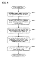
- Fig. 4 is a flowchart showing a process for dyeing the plastic lens.
- inks for the dyeing which is used in an ink jet printer, are prepared in the following manner.
- dyes of three colors; RED, YELLOW, and BLUE are used to prepare inks of four colors (red, yellow, blue, and black).
- Any existing dyes having a sublimatable property are usable for the above dyes.
- hydrophobic disperse dyes are used.
- the dyes are heated to a predetermined temperature to cause sublimation. It is therefore necessary to use dyes capable of resisting the heat generated at sublimation.
- the dyes are put in ink cartridges for the ink jet printer. Therefore the dyes are desired to have a minimum size in diameter.
- the red, yellow, and blue inks are prepared as follows.
- the RED, YELLOW, and BLUE dyes are put in separate vessels. In each vessel, furthermore, pure water and a dispersing agent are added and sufficiently stirred.
- the BLACK ink is produced by mixture of the RED, YELLOW, and BLUE dyes.
- each ink is determined such that a ratio of a dye to the total volume of an ink is preferably 0.1 wt% to 20 wt%, more preferably, 0.5 wt% to 10 wt%. If the dye is less than 0.1 wt%, a desired color density could not be often obtained. If the dye is more than 20 wt%, dispersibility of the dye would become low.
- the dispersing agent to be used is needed to have properties of not decomposing by heat and of resisting heat.
- the four kinds of inks produced in the above manner are poured into separate cartridges. These cartridges are mounted in an ink jet printer (hereinafter, referred to as a printer) 40.
- a printer 40 for the printer 40 and its ink cartridges, commercially available ones may be used.
- a print base body 10 is produced in the following manner.
- the printer 40 under control of a personal computer (hereinafter, referred to as a PC) 50, produces the print base body 10 according to data on graphic designs such as pictures, letters, etc. and data on their color, density, etc.
- a PC 50 a commercially available one may be used.
- a monitor screen 51 of the PC 50 displays a circular line 52 (having the same diameter as that of the plastic lens 3) based on the diameter of the lens 3 previously input by use of a keyboard and the like connected to the PC 50.
- the screen 51 displays a spectacle frame form (frame line) 53 by overlaying it on the circular line 52 based on frame data transmitted from a measuring device (a tracer) 60 shown in Fig. 1 which measures the form (shape) of a frame.
- the positional relation between the circular line 52 and the frame form 53 is determined by a program made in consideration of a geometric or optical center of the lens 3, a distance between pupils of a spectacle wearer, and other correction matters.
- the frame data is obtained by use of the tracer 60, but it is not limited thereto.
- the PC 50 may store data on many frames in advance so that a desired one is selected from among them.
- a graphic design 54 (a flower design in the present embodiment) which has previously been produced is arranged in a desired position within the frame form 53 displayed on the screen 51.
- Data on the graphic design 54 may be obtained by a scanner which reads a desired picture or the like or produced by a drawing software. Alternatively, many graphic design data may be stored in advance in the PC 50 so that a desired one is selected from among them. Color and density of the graphic design 54 are determined based on color data stored in the PC 50 (Step 1).
- the data can be stored in the PC 50 and therefore the same data can be used anytime as required.
- a base body used in the present embodiment, to which the inks for dyeing (the sublimatable dye) are to be printed, is an A4-sized paper 1 which is commercially available.
- the base body is not particularly limited to paper and may be any materials on which the printer 40 can print. Considering that the base body is heated during vapor phase transfer, a substance having good heat-absorbency is preferably used in the present embodiment.
- An operator sets the paper 1 in the printer 40 and operates the PC 50 to print on the paper 1 based on the determined graphic design data. At this time, according to the position (the dyeing position) of the graphic design 54 with respect to the frame form 53, a print area (a colored layer) 2 is printed on the paper 1 (Step 2).
- the printer 40 prints a circular form (line) 2a and a graphic design 2b in the print area 2 on the paper 1.
- the production of the print base body 10 is completed.
- the circular form 2a is a guide (an alignment mark) used for overlapping the print base body 10 (the print area 2) on the lens 3.
- the circular form 2a is preferably printed with the finest and lightest line to prevent the form 2a from being dyed on the lens 3 during the dyeing.
- the peripheral edge of a lens will usually be cut away (ground) at working or machining and thus no problem occurs even if the lens edge is slightly dyed.
- the circular form 2a is required only to have a diameter slightly larger than that of the lens 3.
- the lens 3 can be prevented from being dyed unnecessarily.
- a circle can be identified in form if three points on its periphery are found. Accordingly, plural (three or more) marks may be printed only at points on the periphery instead of printing of the full circular form 2a on the paper 1. These marks are more preferably formed in portions which will be cut away (ground) at the machining. The portions to be cut away (ground) can easily be specified by comparison between the shape (the circular form 2a) of the lens 3 and the frame form 53.
- the paper 1 on which the print area 2 is printed by the printer 40 in the above manner is used as the print base body 10.
- Step 3 the print base body 10 produced as above and the lens 3 are brought into nearly close contact with each other by means of a dyeing jig 30 (Step 3).
- This jig 30 is placed in an oven 20 for performing the transfer and dyeing to the lens 3.
- Fig. 2 is a side view of the dyeing jig 30.
- the dyeing jig 30 is constructed of a pressing member (pad) 31, a lens holder 32, and a pressing tool 33.
- the pressing member 31 is used to press the print base body 10 against the lens 3 to conform to the shape of a surface to be dyed (namely, a curved surface).
- the pressing member 31 is preferably provided with a pressing part being flexible and deformable in correspondence with the shape of the surface of the lens 3 to be dyed.
- the pressing member 31 used in the present embodiment is made of silicone resin. It is also possible to select a desired one from among plural pressing members each having a pressing part with a different shape according to a surface of various lenses.
- the pressing tool 33 is constructed of an upper part 33a and a lower part 33b for sandwiching therebetween the pressing member 31, the print base body 10, and the lens 3, and a drive part 33c for moving the upper part 33a up or down.
- the lens 3 is placed with the concave surface side up in the lens holder 32 disposed on the lower part 33b of the pressing tool 33. Then, the print base body 10 and the pressing member 31 are set in turn on the lens holder 32.
- This lens holder 32 holds the periphery edge of the lens 3 in the present embodiment. It is also possible to use any other holders which hold the portions except the surface of the lens 3 to be dyed.
- the print base body 10 is positioned so that the circular form 2a on the base body 10 is overlaid on the periphery edge of the lens 3.
- the graphic design 2b facing down (facing the lens 3 side) is adjusted to a desired position on the lens 3.
- the drive part 33c is then turned to move the upper part 33a down, thereby sandwiching the pressing member 31, the print base body 10, and the lens 3 from top and bottom.
- the graphic design 2b can be made nearly close contact with a desired position on the lens 3. This makes it possible to transfer and dye the graphic design 2b to a desired position on the lens 3.
- the lens 3 and the print base body 10 are pressed from above to come into contact with each other. Alternatively, they may be pressed from below.
- the pressing force to bring the base body 10 into close contact with the lens 3 is desired to be large as much as possible, while it should be determined in consideration of deformation of the lens and other conditions.
- the pressing force is preferably determined in the range of 10 kPa to 500 kPa, more preferably, in the range of 200 kPa to 400 kPa. If the pressing force is less than 10 kPa, the force of pressing down the base body 10 and the lens 3 becomes insufficient. As a result thereof, the graphic design dyed on the lens 3 may be blurred. If the pressure exceeds 500 kPa, on the other hand, the lens 3 may be deformed or cracked.
- the material of the lens 3 to be dyed is appropriately selected from among general materials usable for lenses for eye such as spectacle lenses; for example, a polycarbonate resin (e.g. diethylene glycol bisallyl carbonate polymer (CR-39)), a polyurethane resin, an allyl resin (e.g. allyl diglycol carbonate and the copolymer, and diallyl phthalate and the copolymer), a fumaric resin (e.g. benzyl fumarate copolymer), a styrene resin, a polymethyl acrylate resin, a fiber resin (e.g. cellulose propionate).
- a polycarbonate resin e.g. diethylene glycol bisallyl carbonate polymer (CR-39)
- a polyurethane resin e.g. allyl diglycol carbonate and the copolymer, and diallyl phthalate and the copolymer
- a fumaric resin e.g. benzyl fumarate
- the heating temperature in the oven 20 is preferably set at as high a temperature as possible in a temperature range where deterioration of the dye and deformation of the lens will not occur.
- the heating temperature is preferably determined in the range of 80°C to 200°C, more preferably in the range of 100°C to 150°C. If the heating temperature is below 80°C, the dye is unlikely to sublime sufficiently and therefore the lens 3 could not be dyed satisfactorily. The heating temperature may be raised beyond 200°C.
- the heating time may be determined appropriately if only almost all the dye can sublime from the base body 10.
- the heating time is set in the range of about 30 min. to 90 min.
- the print base body 10 not only the print base body 10 but also the lens 3 is heated.
- only the base body 10 may be heated.
- an electrically heating wire or the like is provided in advance in the pressing member 31 so that heat is generated from the pressing member 31, which heats only the base body 10.
- the lens 3 is taken out of the dyeing jig 30. The dyeing is thus completed.
- a hard coating may be applied to the lens 3 in order to protect the lens and prevent fading of the dye (Step 5).
- the composition of the hard coating is suitably selected from among compositions generally used for a hard coating, for example, a hydrolytic product such as alkoxysilane, a metal oxide, and a curing catalyst.
- a hydrolytic product such as alkoxysilane, a metal oxide, and a curing catalyst.
- alkoxysilane are methyl trimethoxy silane, ethyl trimethoxy silane, ⁇ -glycidoxy trimethoxy silane, ⁇ -glycidoxy propyl trimethoxy silane, or the like.
- titania is mentioned.
- Other examples of the metal oxide are an oxide of metal such as aluminum, iron, zirconium, indium, etc.
- amines such as guanidine, triethylamine, and aniline, etc.
- metal chelate such as chromium(III) in which acetylacetone is coordinated, iron(III), zirconium(IV), etc.
- metallic salt such as tin chloride, iron chloride, aluminum chloride, etc.
- a solvent usable for this hard coating solution is alcohols such as methyl alcohol and ethyl alcohol; ketones such as ethyl acetate; and ethers such as diethyl ether.
- a coating method of the hard coating solution to the lens 3 after the dyeing is appropriately selected from among generally used coating methods such as dip coating, roller coating, spray coating, spin coating.
- As a pretreatment to the lens 3 prior to the coating ultrasonic cleaning, alkali treatment, plasma (RF) treatment, or another kind of treatment may be conducted.
- a process for drying the lens 3 is performed.
- a warm air drying method an infrared drying method, a CH drying method (a coagulation-heating method), a UV drying method, and another kind of drying method may be used.
- a CR-39 lens is used.
- Dyes used are Kayaron Polyester RED BS200 made by Nippon Kayaku Co., Ltd. for a RED dye, Kayaron Michroester AQ-LE made by Nippon Kayaku Co., Ltd. for a YELLOW dye, and Dianix BLUE AC-E made by DyStar Japan Co., Ltd. for a BLUE dye.
- a dispersing agent used is DEMOL MS made by Kao Corporation.
- Table 1 shows the composition of each ink which is filled in each ink cartridge.
- the dye, dispersing agent, and pure water for each ink are mixed at the above composition in each vessel and stirred for 10 min. or more. Subsequently, the mixture in each vessel is processed by an ultrasonic homogenizer for a predetermined time (30 min. for about 100 gram of each mixture) to homogenize dye particles into primary particles. Then, each mixture solution is suction-filtered by a filter having pores of a size of about 0.7 ⁇ m, so that particles of a large size, dregs, and the like are removed. A proper quantity of pure water is further added to each mixture solution after the suction-filtering to adjust the density. Each dyeing ink is thus produced.
- the dyeing inks produced as above are filled in ink cartridges of the ink jet printer 40 (MJ-500C made by EPSON Corporation), respectively.
- the commercially available paper 1 gloss paper (black) made by the Mitsubishi Paper Mills Limited
- the flower graphic design 2b is printed on the paper 1 by use of a drawing software installed in the PC 50 and the printer 40.
- the base body 10 is produced. It is to be noted that the color of the graphic design is set at R150, G100, and B50.
- the lens 3 and the base body 10 are placed in a nearly close contact relation in the dyeing jig 30.
- the transfer work (dyeing work) from the base body 10 to the lens 3 is conducted under conditions that the heating temperature in the oven 20 is set at 135°C and the heating time is set for 1 hour.
- the heating temperature in the oven 20 is set at 135°C and the heating time is set for 1 hour.
- the dyeing is conducted on the concave surface of the lens in the above embodiment, it may alternatively be performed on the convex surface.
- the concave surface is preferred.
- a desired graphic design such as pictures, letters, or the like can be easily dyed on a plastic lens.
Landscapes
- Ophthalmology & Optometry (AREA)
- Engineering & Computer Science (AREA)
- Health & Medical Sciences (AREA)
- Physics & Mathematics (AREA)
- General Physics & Mathematics (AREA)
- General Health & Medical Sciences (AREA)
- Textile Engineering (AREA)
- Optics & Photonics (AREA)
- Manufacturing & Machinery (AREA)
- Mechanical Engineering (AREA)
- Coloring (AREA)
- Eyeglasses (AREA)
- Surface Treatment Of Optical Elements (AREA)
Abstract
Description
- The present invention relates to a method of dyeing a plastic lens by vapor phase transfer, a plastic lens obtained by use of the dyeing method, and a dyeing system, a dyeing device, and a dyeing jig for a plastic lens to implement the dyeing method.
- Heretofore, there have been known lenses with graphic designs such as pictures and letters. These designs are given to the lenses by affix of seals on which pictures, letters, and the like are printed or by silk-screen printing on lens surfaces.
- Such the pictures and letters applied on the lens surfaces by the seals or the silk-screen printing tend to peel as time passes. Instead of the printing on the lens surfaces, dyeing pictures, letters, and the like on lenses may solve the above problem. However, there has been proposed no method of dyeing the pictures, letters, and the like on lenses.
- The present invention has been made in view of the above circumstances and has an object to overcome the above problems and to provide a method of easily dyeing desired graphic designs such as pictures and letters on a plastic lens, a plastic lens obtained by use of the dyeing method, and a dyeing system, a dyeing device, and a dyeing jig for implementing the dyeing method to easily dye the desired graphic designs on a plastic lens.
- Additional objects and advantages of the invention will be set forth in part in the description which follows and in part will be obvious from the description, or may be learned by practice of the invention. The objects and advantages of the invention may be realized and attained by means of the instrumentalities and combinations particularly pointed out in the appended claims.
- To achieve the purpose of the invention, in a first aspect, there is provided (1) a method of dyeing a plastic lens, characterized by including: a producing step of producing a print base body on which a print area is printed with a sublimatable dye by a printer under control of a computer, the printer being previously supplied with the dye; a placing step of placing the print base body and a lens to be dyed so that the print area on the base body is brought into nearly close contact with a lens surface to be dyed; and a transferring step of heating at least the print base body to sublimate the sublimatable dye of the print area, thereby transferring the dye to the lens surface to be dyed.
- (2) In the method (1), preferably, the placing step includes pressing the print base body against the lens by pressing means to bring the print area into nearly close contact with the lens surface to be dyed.
- (3) In the method (1), preferably, the transferring step includes heating both the lens and the print base body.
- (4) Preferably, the method (1) further includes an input step of inputting data on a desired graphic design and data on color of the design into the computer, wherein the producing step includes printing the print area based on the input data to produce the print base body.
- (5) In the method (4), preferably, the input step includes inputting data on position of the graphic design with respect to the lens to be dyed.
- (6) The method (1) preferably further includes a step of applying a hard coat to the lens after the dye is transferred thereto.
- (7) In a second aspect, the present invention is directed to a plastic lens obtained by use of the dyeing method (1).
- (8) The lens (7) preferably includes a lens which has a curved surface and is used for eye.
- (9) In a third aspect, the present invention is directed to a dyeing system for a plastic lens, characterized by including: a computer which stores at least color data and into which data on a desired graphic design and data on color of the design are input; a printer which is connected to the computer and supplied with a sublimatable dye, and prints a print area with the dye based on the input data under control of the computer to produce a print base body; a placing unit which places the print base body and a lens to be dyed so that the print area on the print base body is brought into nearly close contact with a lens surface to be dyed; and a transferring unit which heats at least the print base body to sublimate the sublimatable dye of the print area to transfer the dye to the lens surface to be dyed.
- (10) In the dyeing system (9), preferably, the placing unit includes: a lens holder for holding the lens to be dyed; a pressing member including a pressing part having a shape substantially corresponding to a shape of the lens surface to be dyed; and a pressing unit for applying a pressing force to the lens and the pressing member which are in nearly close contact with each other through the print base body, from a side of at least one of the lens and the pressing member.
- (11) In the dyeing system (9), preferably, the transferring unit heats both the lens and the print base body.
- (12) In the dyeing system (9), preferably, the printer includes an ink jet printer.
- (13) In a fourth aspect, the present invention is directed to a dyeingdevice foraplastic lens, characterized by including: a lens holder for holding a lens to be dyed; a pressing member including a pressing part having a shape substantially corresponding to a shape of a lens surface to be dyed; a pressing unit for applying a pressing force to the lens and the pressing member which are in nearly close contact with each other through a print base body, from a side of at least one of the lens and the pressing member; and a heating unit for heating at least the print base body.
- (14) In the dyeing device (13), preferably, the heating unit heats both the lens and the print base body.
- (15) In a fifth aspect, the present invention is directed to a dyeing jig for dyeing a plastic lens, characterized by including; a lens holder for holding a lens to be dyed; a pressing member including a pressing part having a shape substantially corresponding to a shape of a lens surface to be dyed; and a pressing unit for applying a pressing force to the lens and the pressing member which are in nearly close contact with each other through a print base body, from a side of at least one of the lens and the pressing member.
- (16) In the dyeing jig (15), preferably, at least the pressing part of the pressing member is made of a material deformable in correspondence with the lens surface to be dyed.
- (17) In the dyeing jig (16), preferably, at least the pressing part of the pressing member is made of a silicone resin.
- (18) In the dyeing jig (15), preferably, the pressing unit is provided with a member for holding the lens and the pressing member in nearly close contact with each other through the print base body.
-
- The accompanying drawings, which are incorporated in and constitute a part of this specification illustrate an embodiment of the invention and, together with the description, serve to explain the objects, advantages and principles of the invention.
- In the drawings,
- Fig. 1 is a schematic structural view of a dyeing system for dyeing a plastic lens in an embodiment according to the present invention;
- Fig. 2 is a schematic side view of a structure using a dyeing jig to hold a plastic lens and a print base body in nearly close contact with each other;
- Fig. 3A is a view of an example of a screen of a personal computer for producing the print base body;
- Fig. 3B is a view showing the print base body produced according to the screen shown in Fig. 3A; and
- Fig. 4 is a flowchart showing a process for dyeing a plastic lens in the embodiment according to the present invention.
-
- A detailed description of a preferred embodiment according to the present invention will now be given referring to the accompanying drawings. Fig. 1 is a schematic structural view of a dyeing system for dyeing a plastic lens. Fig. 4 is a flowchart showing a process for dyeing the plastic lens.
- First of all (prior to dyeing) inks for the dyeing, which is used in an ink jet printer, are prepared in the following manner. In the present embodiment, dyes of three colors; RED, YELLOW, and BLUE are used to prepare inks of four colors (red, yellow, blue, and black). Any existing dyes having a sublimatable property (dyes including sublimatable pigments) are usable for the above dyes. Preferably, hydrophobic disperse dyes are used. In the present embodiment, the dyes are heated to a predetermined temperature to cause sublimation. It is therefore necessary to use dyes capable of resisting the heat generated at sublimation. For actual use, the dyes are put in ink cartridges for the ink jet printer. Therefore the dyes are desired to have a minimum size in diameter.
- The red, yellow, and blue inks are prepared as follows. The RED, YELLOW, and BLUE dyes are put in separate vessels. In each vessel, furthermore, pure water and a dispersing agent are added and sufficiently stirred. The BLACK ink is produced by mixture of the RED, YELLOW, and BLUE dyes.
- The prescription of each ink is determined such that a ratio of a dye to the total volume of an ink is preferably 0.1 wt% to 20 wt%, more preferably, 0.5 wt% to 10 wt%. If the dye is less than 0.1 wt%, a desired color density could not be often obtained. If the dye is more than 20 wt%, dispersibility of the dye would become low. The dispersing agent to be used is needed to have properties of not decomposing by heat and of resisting heat.
- After the dye, dispersing agent, and pure water are sufficiently mixed in each vessel, these vessels containing respective mixtures are placed in a container in which cooling wateris filled. Then, aprocessusinganultrasonichomogenizer is carried out for a predetermined time to regulate the particle size of each dye to a desired diameter. After that, a filter (glass fiber filter paper GF/B) having pores of a size of about 0.5µm to 1µm is used to suction-filter each mixture to remove particles of a large size, dregs and the like. Sequentially, pure water is further added to adjust each mixture to a desired density. Thus, the ink production is completed.
- The four kinds of inks produced in the above manner are poured into separate cartridges. These cartridges are mounted in an ink jet printer (hereinafter, referred to as a printer) 40. For the
printer 40 and its ink cartridges, commercially available ones may be used. - With the
printer 40, aprint base body 10 is produced in the following manner. Theprinter 40, under control of a personal computer (hereinafter, referred to as a PC) 50, produces theprint base body 10 according to data on graphic designs such as pictures, letters, etc. and data on their color, density, etc. For thePC 50, a commercially available one may be used. - To be more specific, as shown in Fig. 3A, a
monitor screen 51 of thePC 50 displays a circular line 52 (having the same diameter as that of the plastic lens 3) based on the diameter of thelens 3 previously input by use of a keyboard and the like connected to thePC 50. Simultaneously, thescreen 51 displays a spectacle frame form (frame line) 53 by overlaying it on thecircular line 52 based on frame data transmitted from a measuring device (a tracer) 60 shown in Fig. 1 which measures the form (shape) of a frame. The positional relation between thecircular line 52 and the frame form 53 is determined by a program made in consideration of a geometric or optical center of thelens 3, a distance between pupils of a spectacle wearer, and other correction matters. - In the present embodiment, the frame data is obtained by use of the
tracer 60, but it is not limited thereto. ThePC 50 may store data on many frames in advance so that a desired one is selected from among them. - A graphic design 54 (a flower design in the present embodiment) which has previously been produced is arranged in a desired position within the frame form 53 displayed on the
screen 51. Data on the graphic design 54 may be obtained by a scanner which reads a desired picture or the like or produced by a drawing software. Alternatively, many graphic design data may be stored in advance in thePC 50 so that a desired one is selected from among them. Color and density of the graphic design 54 are determined based on color data stored in the PC 50 (Step 1). - Since the
PC 50 is used as above, the data can be stored in thePC 50 and therefore the same data can be used anytime as required. - A base body used in the present embodiment, to which the inks for dyeing (the sublimatable dye) are to be printed, is an A4-
sized paper 1 which is commercially available. The base body is not particularly limited to paper and may be any materials on which theprinter 40 can print. Considering that the base body is heated during vapor phase transfer, a substance having good heat-absorbency is preferably used in the present embodiment. - An operator sets the
paper 1 in theprinter 40 and operates thePC 50 to print on thepaper 1 based on the determined graphic design data. At this time, according to the position (the dyeing position) of the graphic design 54 with respect to the frame form 53, a print area (a colored layer) 2 is printed on the paper 1 (Step 2). - As shown in Fig. 3B, the
printer 40 prints a circular form (line) 2a and agraphic design 2b in theprint area 2 on thepaper 1. Thus, the production of theprint base body 10 is completed. - The
circular form 2a is a guide (an alignment mark) used for overlapping the print base body 10 (the print area 2) on thelens 3. Thecircular form 2a is preferably printed with the finest and lightest line to prevent theform 2a from being dyed on thelens 3 during the dyeing. However, the peripheral edge of a lens will usually be cut away (ground) at working or machining and thus no problem occurs even if the lens edge is slightly dyed. - In the case that the lens is worked or machined without cutting away (grinding) a part of the peripheral edge, the
circular form 2a is required only to have a diameter slightly larger than that of thelens 3. Thus, thelens 3 can be prevented from being dyed unnecessarily. In general, a circle can be identified in form if three points on its periphery are found. Accordingly, plural (three or more) marks may be printed only at points on the periphery instead of printing of the fullcircular form 2a on thepaper 1. These marks are more preferably formed in portions which will be cut away (ground) at the machining. The portions to be cut away (ground) can easily be specified by comparison between the shape (thecircular form 2a) of thelens 3 and the frame form 53. - The
paper 1 on which theprint area 2 is printed by theprinter 40 in the above manner is used as theprint base body 10. - Subsequently, the
print base body 10 produced as above and thelens 3 are brought into nearly close contact with each other by means of a dyeing jig 30 (Step 3). Thisjig 30 is placed in anoven 20 for performing the transfer and dyeing to thelens 3. Fig. 2 is a side view of thedyeing jig 30. - The
dyeing jig 30 is constructed of a pressing member (pad) 31, alens holder 32, and apressing tool 33. The pressingmember 31 is used to press theprint base body 10 against thelens 3 to conform to the shape of a surface to be dyed (namely, a curved surface). For this purpose, the pressingmember 31 is preferably provided with a pressing part being flexible and deformable in correspondence with the shape of the surface of thelens 3 to be dyed. The pressingmember 31 used in the present embodiment is made of silicone resin. It is also possible to select a desired one from among plural pressing members each having a pressing part with a different shape according to a surface of various lenses. - The
pressing tool 33 is constructed of anupper part 33a and alower part 33b for sandwiching therebetween the pressingmember 31, theprint base body 10, and thelens 3, and adrive part 33c for moving theupper part 33a up or down. - The
lens 3 is placed with the concave surface side up in thelens holder 32 disposed on thelower part 33b of thepressing tool 33. Then, theprint base body 10 and the pressingmember 31 are set in turn on thelens holder 32. Thislens holder 32 holds the periphery edge of thelens 3 in the present embodiment. It is also possible to use any other holders which hold the portions except the surface of thelens 3 to be dyed. - At the above setting, the
print base body 10 is positioned so that thecircular form 2a on thebase body 10 is overlaid on the periphery edge of thelens 3. Also, thegraphic design 2b facing down (facing thelens 3 side) is adjusted to a desired position on thelens 3. Thedrive part 33c is then turned to move theupper part 33a down, thereby sandwiching the pressingmember 31, theprint base body 10, and thelens 3 from top and bottom. As a result, thegraphic design 2b can be made nearly close contact with a desired position on thelens 3. This makes it possible to transfer and dye thegraphic design 2b to a desired position on thelens 3. - In the present embodiment, the
lens 3 and theprint base body 10 are pressed from above to come into contact with each other. Alternatively, they may be pressed from below. - The pressing force to bring the
base body 10 into close contact with thelens 3 is desired to be large as much as possible, while it should be determined in consideration of deformation of the lens and other conditions. The pressing force is preferably determined in the range of 10 kPa to 500 kPa, more preferably, in the range of 200 kPa to 400 kPa. If the pressing force is less than 10 kPa, the force of pressing down thebase body 10 and thelens 3 becomes insufficient. As a result thereof, the graphic design dyed on thelens 3 may be blurred. If the pressure exceeds 500 kPa, on the other hand, thelens 3 may be deformed or cracked. - The material of the
lens 3 to be dyed is appropriately selected from among general materials usable for lenses for eye such as spectacle lenses; for example, a polycarbonate resin (e.g. diethylene glycol bisallyl carbonate polymer (CR-39)), a polyurethane resin, an allyl resin (e.g. allyl diglycol carbonate and the copolymer, and diallyl phthalate and the copolymer), a fumaric resin (e.g. benzyl fumarate copolymer), a styrene resin, a polymethyl acrylate resin, a fiber resin (e.g. cellulose propionate). - After the
lens 3 and theprint base body 10 are placed as above in thedyeing jig 30, they are put in theoven 20 and heated under normal pressure to carry out the transfer and dyeing to the lens 3 (Step 4). The heating temperature in theoven 20 is preferably set at as high a temperature as possible in a temperature range where deterioration of the dye and deformation of the lens will not occur. The heating temperature is preferably determined in the range of 80°C to 200°C, more preferably in the range of 100°C to 150°C. If the heating temperature is below 80°C, the dye is unlikely to sublime sufficiently and therefore thelens 3 could not be dyed satisfactorily. The heating temperature may be raised beyond 200°C. At such high temperatures, however, the dye is apt to deteriorate in quality and thelens 3 tends to be deformed. The heating time may be determined appropriately if only almost all the dye can sublime from thebase body 10. For example, the heating time is set in the range of about 30 min. to 90 min. - In the present embodiment, not only the
print base body 10 but also thelens 3 is heated. Alternatively, only thebase body 10 may be heated. In this case, an electrically heating wire or the like is provided in advance in the pressingmember 31 so that heat is generated from the pressingmember 31, which heats only thebase body 10. After finish of the transfer and dyeing in theoven 20, thelens 3 is taken out of thedyeing jig 30. The dyeing is thus completed. - After the dyeing, a hard coating may be applied to the
lens 3 in order to protect the lens and prevent fading of the dye (Step 5). - The composition of the hard coating is suitably selected from among compositions generally used for a hard coating, for example, a hydrolytic product such as alkoxysilane, a metal oxide, and a curing catalyst. Exemplified as the alkoxysilane are methyl trimethoxy silane, ethyl trimethoxy silane, γ-glycidoxy trimethoxy silane, γ-glycidoxy propyl trimethoxy silane, or the like. As the metal oxide, titania is mentioned. Other examples of the metal oxide are an oxide of metal such as aluminum, iron, zirconium, indium, etc. Exemplified as the curing catalyst are amines, metal chelate, and metallic salt, etc.; more specifically, amines such as guanidine, triethylamine, and aniline, etc.; metal chelate such as chromium(III) in which acetylacetone is coordinated, iron(III), zirconium(IV), etc.; and metallic salt such as tin chloride, iron chloride, aluminum chloride, etc.
- The above mentioned materials are properly combined to produce a hard coating solution. A solvent usable for this hard coating solution is alcohols such as methyl alcohol and ethyl alcohol; ketones such as ethyl acetate; and ethers such as diethyl ether.
- A coating method of the hard coating solution to the
lens 3 after the dyeing is appropriately selected from among generally used coating methods such as dip coating, roller coating, spray coating, spin coating. As a pretreatment to thelens 3 prior to the coating, ultrasonic cleaning, alkali treatment, plasma (RF) treatment, or another kind of treatment may be conducted. - After application of the hard coating to the
lens 3, a process for drying thelens 3 is performed. For this drying method, a warm air drying method, an infrared drying method, a CH drying method (a coagulation-heating method), a UV drying method, and another kind of drying method may be used. - Next, a concrete example of the dyeing method is shown.
- In this example, a CR-39 lens is used. Dyes used are Kayaron Polyester RED BS200 made by Nippon Kayaku Co., Ltd. for a RED dye, Kayaron Michroester AQ-LE made by Nippon Kayaku Co., Ltd. for a YELLOW dye, and Dianix BLUE AC-E made by DyStar Japan Co., Ltd. for a BLUE dye. A dispersing agent used is DEMOL MS made by Kao Corporation.
- Table 1 shows the composition of each ink which is filled in each ink cartridge. The ratio between the three colors of dyes for production of a black ink is RED:YELLOW:BLUE=1:2:2.
RED INK YELLOW INK BLUE INK BLACK INK DYE 5.0% 5.0% 5.0% 5.0% DISPERSING AGENT 3.0% 3.0% 3.0% 3.0% PURE WATER 92.0% 92.0% 92.0% 92.0% - In the table 1, "%" stands for a weight percent.
- The dye, dispersing agent, and pure water for each ink are mixed at the above composition in each vessel and stirred for 10 min. or more. Subsequently, the mixture in each vessel is processed by an ultrasonic homogenizer for a predetermined time (30 min. for about 100 gram of each mixture) to homogenize dye particles into primary particles. Then, each mixture solution is suction-filtered by a filter having pores of a size of about 0.7µm, so that particles of a large size, dregs, and the like are removed. A proper quantity of pure water is further added to each mixture solution after the suction-filtering to adjust the density. Each dyeing ink is thus produced.
- The dyeing inks produced as above (the RED ink, the YELLOW ink, the BLUE ink, and the BLACK ink) are filled in ink cartridges of the ink jet printer 40 (MJ-500C made by EPSON Corporation), respectively. The commercially available paper 1 (gloss paper (black) made by the Mitsubishi Paper Mills Limited) is used for production of the
print base body 10. The flowergraphic design 2b is printed on thepaper 1 by use of a drawing software installed in thePC 50 and theprinter 40. Thebase body 10 is produced. It is to be noted that the color of the graphic design is set at R150, G100, and B50. - After the
print base body 10 is dried, thelens 3 and thebase body 10 are placed in a nearly close contact relation in thedyeing jig 30. The transfer work (dyeing work) from thebase body 10 to thelens 3 is conducted under conditions that the heating temperature in theoven 20 is set at 135°C and the heating time is set for 1 hour. By this transfer work to thelens 3, a clean flower graphic design can be dyed on the surface of thelens 3. - Although the dyeing is conducted on the concave surface of the lens in the above embodiment, it may alternatively be performed on the convex surface. However, the concave surface is preferred.
- As explained above, according to the present invention, a desired graphic design such as pictures, letters, or the like can be easily dyed on a plastic lens.
- While the presently preferred embodiment of the present invention has been shown and described, it is to be understood that this disclosure is for the purpose of illustration and that various changes and modifications may be made without departing from the scope of the invention as set forth in the appended claims.
Claims (13)
- A method of dyeing a plastic lens (3), characterized by including:a producing step of producing a print base body (10) on which a print area (2b) is printed with a sublimatable dye by a printer (40) under control of a computer (50), the printer being previously supplied with the dye;a placing step of placing the print base body and a lens (3) to be dyed so that the print area on the base body is brought into nearly close contact with a lens surface to be dyed; anda transferring step of heating at least the print base body to sublimate the sublimatable dye of the print area, thereby transferring the dye to the lens surface to be dyed.
- The dyeing method according to claim 1, wherein the placing step includes pressing the print base body against the lens by pressing means (31) to bring the print area into nearly close contact with the lens surface to be dyed and/or wherein the transferring step includes heating both the lens and the print base body.
- The dyeing method according to claim 1 or 2, further including an input step of inputting data on a desired graphic design and data on color of the design into the computer,
wherein the producing step includes printing the print area based on the input data to produce the print base body, the input step preferably includes inputting data on position of the graphic design with respect to the lens to be dyed. - The dyeing method according to one of claims 1 to 3, further including a step of applying a hard coat to the lens after the dye is transferred thereto.
- A plastic lens obtained by use of the dyeing method according to one of claims 1 to 4, preferably having a curved surface and is used for eye.
- A dyeing system for a plastic lens (3), characterized by including:a computer (50) which stores at least color data and into which data on a desired graphic design and data on color of the design are input;a printer (40) which is connected to the computer and supplied with a sublimatable dye, and prints a print area (2b) with the dye based on the input data under control of the computer to produce a print base body (10);a placing unit (30) which places the print base body and a lens (3) to be dyed so that the print area on the print base body is brought into nearly close contact with a lens surface to be dyed; anda transferring unit (20) which heats at least the print base body to sublimate the sublimatable dye of the print area to transfer the dye to the lens surface to be dyed.
- The dyeing system according to claim 6, wherein the placing unit includes:a lens holder (32) for holding the lens to be dyed;a pressing member (31) including a pressing part having a shape substantially corresponding to a shape of the lens surface to be dyed; anda pressing unit (33) for applying a pressing force to the lens and the pressing member which are in nearly close contact with each other through the print base body, from a side of at least one of the lens and the pressing member.
- The dyeing system according to claim 6 0r 7, wherein the transferring unit heats both the lens and the print base body, and/or wherein the printer includes an ink jet printer (40).
- A dyeing device for a plastic lens (3), characterized by including:a lens holder (32) for holding a lens (3) to be dyed;a pressing member (31) including a pressing part having a shape substantially corresponding to a shape of a lens surface to be dyed;a pressing unit (33) for applying a pressing force to the lens and the pressing member which are in nearly close contact with each other through a print base body (10), from a side of at least one of the lens and the pressing member; anda heating unit (20) for heating at least the print base body.
- The dyeing device according to claim 9, wherein the heating unit heats both the lens and the print base body.
- A dyeing jig (30) for dyeing a plastic lens (3), characterized by including:a lens holder (32) for holding a lens (3) to be dyed;a pressing member (31) including a pressing part having a shape substantially corresponding to a shape of a lens surface to be dyed; anda pressing unit (33) for applying a pressing force to the lens and the pressing member which are in nearly close contact with each other through a print base body (10), from a side of at least one of the lens and the pressing member.
- The dyeing jig according to claim 11, wherein at least the pressing part of the pressing member is made of a material deformable in correspondence with the lens surface to be dyed, preferably made of a silicone resin.
- The dyeing jig according to claim 11 or 12, wherein the pressing unit is provided with a member for holding the lens and the pressing member in nearly close contact with each other through the print base body.
Applications Claiming Priority (2)
| Application Number | Priority Date | Filing Date | Title |
|---|---|---|---|
| JP2001059081 | 2001-03-02 | ||
| JP2001059081A JP4268766B2 (en) | 2001-03-02 | 2001-03-02 | Plastic lens dyeing method and plastic lens obtained by using the method |
Publications (2)
| Publication Number | Publication Date |
|---|---|
| EP1237035A1 true EP1237035A1 (en) | 2002-09-04 |
| EP1237035B1 EP1237035B1 (en) | 2005-11-23 |
Family
ID=18918703
Family Applications (1)
| Application Number | Title | Priority Date | Filing Date |
|---|---|---|---|
| EP02004533A Expired - Lifetime EP1237035B1 (en) | 2001-03-02 | 2002-02-27 | A method of dyeing a plastic lens, a plastic lens obtained by use of the dyeing method, and a dyeing system, a dyeing device, and a dyeing jig for a plastic lens |
Country Status (6)
| Country | Link |
|---|---|
| US (1) | US6736863B2 (en) |
| EP (1) | EP1237035B1 (en) |
| JP (1) | JP4268766B2 (en) |
| AT (1) | ATE310973T1 (en) |
| DE (1) | DE60207460T2 (en) |
| ES (1) | ES2253460T3 (en) |
Cited By (3)
| Publication number | Priority date | Publication date | Assignee | Title |
|---|---|---|---|---|
| JP3512725B2 (en) | 2000-09-07 | 2004-03-31 | Hoya株式会社 | Method and apparatus for coloring plastic lens |
| EP3629079A1 (en) | 2018-09-27 | 2020-04-01 | Essilor International | An ophthalmic lens for improving night driving vision and a method for obtaining the same |
| WO2020064963A1 (en) | 2018-09-27 | 2020-04-02 | Essilor International | An ophthalmic lens for improving vision |
Families Citing this family (13)
| Publication number | Priority date | Publication date | Assignee | Title |
|---|---|---|---|---|
| JP4554160B2 (en) * | 2003-01-28 | 2010-09-29 | セイコーオプティカルプロダクツ株式会社 | Plastic lens dyeing method |
| JP2005215038A (en) * | 2004-01-27 | 2005-08-11 | Seiko Epson Corp | Eyeglass lenses |
| JP2006113094A (en) * | 2004-10-12 | 2006-04-27 | Seiko Epson Corp | Method for producing dyed plastic lens |
| JP4988404B2 (en) | 2006-09-29 | 2012-08-01 | 株式会社ニデック | Plastic lens dyeing method and plastic lens dyeing substrate producing apparatus |
| US8157872B2 (en) * | 2006-10-06 | 2012-04-17 | Becvar James E | System and method for creating ink art |
| US20080273073A1 (en) * | 2007-05-01 | 2008-11-06 | Gentex Optics, Inc. | System and method for application of ink formulations onto ophthalmic lenses |
| JP5897342B2 (en) * | 2011-01-31 | 2016-03-30 | Hoya株式会社 | Decorative dyed plastic lens |
| JP6113412B2 (en) * | 2011-02-28 | 2017-04-12 | Hoya株式会社 | Manufacturing method of optical lens |
| JP6010349B2 (en) * | 2011-06-09 | 2016-10-19 | 株式会社ニデック | Dyeing method and dyeing apparatus |
| JP2013171087A (en) * | 2012-02-17 | 2013-09-02 | Hoya Lense Manufacturing Philippine Inc | Optical member and method for manufacturing optical member |
| US11536875B2 (en) * | 2019-04-02 | 2022-12-27 | Kh9100 Llc | Method for sublimation coating on optical lens |
| KR102931571B1 (en) | 2019-07-30 | 2026-02-27 | 가부시키가이샤 니데크 | Dying system |
| JP7532778B2 (en) * | 2019-07-30 | 2024-08-14 | 株式会社ニデック | Dyeing tray |
Citations (6)
| Publication number | Priority date | Publication date | Assignee | Title |
|---|---|---|---|---|
| JPS56153321A (en) * | 1980-04-28 | 1981-11-27 | Seiko Epson Corp | Color coated lens |
| JPH01277814A (en) * | 1988-04-30 | 1989-11-08 | Hoya Corp | Method of dyeing plastic lens |
| JPH0223314A (en) * | 1988-07-12 | 1990-01-25 | Menikon:Kk | Dyeing method for hard contact lens and dyed hard contact lens |
| JP2000009905A (en) * | 1998-06-24 | 2000-01-14 | Nidek Co Ltd | Dyeing method and transfer device for plastic lens |
| EP0982432A2 (en) * | 1998-08-27 | 2000-03-01 | Nidek Co., Ltd. | Method of dyeing plastic lens and a dyeing system used therein |
| EP1122355A1 (en) * | 2000-02-04 | 2001-08-08 | Nidek Co., Ltd. | Dyeing method of dyeing plastic lens, dyeing device, and dyeing jig |
Family Cites Families (4)
| Publication number | Priority date | Publication date | Assignee | Title |
|---|---|---|---|---|
| US5052337A (en) * | 1988-10-31 | 1991-10-01 | Talcott Thomas D | Lens dyeing method and apparatus comprising heating element contacting dyeing tank, heat controller and sensor for dye solution temperature |
| US5302223A (en) * | 1990-07-09 | 1994-04-12 | Sawgrass Systems, Inc. | Permanent heat sensitive transfer printing process |
| JP3229291B2 (en) | 1999-05-21 | 2001-11-19 | ホーヤ株式会社 | Plastic lens coloring method and plastic lens coloring apparatus |
| JP4014345B2 (en) * | 2000-02-04 | 2007-11-28 | 株式会社ニデック | Plastic lens dyeing method and dyeing substrate |
-
2001
- 2001-03-02 JP JP2001059081A patent/JP4268766B2/en not_active Expired - Lifetime
-
2002
- 2002-02-26 US US10/082,224 patent/US6736863B2/en not_active Expired - Lifetime
- 2002-02-27 DE DE60207460T patent/DE60207460T2/en not_active Expired - Lifetime
- 2002-02-27 EP EP02004533A patent/EP1237035B1/en not_active Expired - Lifetime
- 2002-02-27 ES ES02004533T patent/ES2253460T3/en not_active Expired - Lifetime
- 2002-02-27 AT AT02004533T patent/ATE310973T1/en not_active IP Right Cessation
Patent Citations (6)
| Publication number | Priority date | Publication date | Assignee | Title |
|---|---|---|---|---|
| JPS56153321A (en) * | 1980-04-28 | 1981-11-27 | Seiko Epson Corp | Color coated lens |
| JPH01277814A (en) * | 1988-04-30 | 1989-11-08 | Hoya Corp | Method of dyeing plastic lens |
| JPH0223314A (en) * | 1988-07-12 | 1990-01-25 | Menikon:Kk | Dyeing method for hard contact lens and dyed hard contact lens |
| JP2000009905A (en) * | 1998-06-24 | 2000-01-14 | Nidek Co Ltd | Dyeing method and transfer device for plastic lens |
| EP0982432A2 (en) * | 1998-08-27 | 2000-03-01 | Nidek Co., Ltd. | Method of dyeing plastic lens and a dyeing system used therein |
| EP1122355A1 (en) * | 2000-02-04 | 2001-08-08 | Nidek Co., Ltd. | Dyeing method of dyeing plastic lens, dyeing device, and dyeing jig |
Non-Patent Citations (4)
| Title |
|---|
| PATENT ABSTRACTS OF JAPAN vol. 006, no. 034 (P - 104) 2 March 1982 (1982-03-02) * |
| PATENT ABSTRACTS OF JAPAN vol. 014, no. 048 (P - 0997) 29 January 1990 (1990-01-29) * |
| PATENT ABSTRACTS OF JAPAN vol. 014, no. 167 (P - 1031) 30 March 1990 (1990-03-30) * |
| PATENT ABSTRACTS OF JAPAN vol. 2000, no. 04 31 August 2000 (2000-08-31) * |
Cited By (5)
| Publication number | Priority date | Publication date | Assignee | Title |
|---|---|---|---|---|
| JP3512725B2 (en) | 2000-09-07 | 2004-03-31 | Hoya株式会社 | Method and apparatus for coloring plastic lens |
| EP3629079A1 (en) | 2018-09-27 | 2020-04-01 | Essilor International | An ophthalmic lens for improving night driving vision and a method for obtaining the same |
| WO2020064640A1 (en) | 2018-09-27 | 2020-04-02 | Essilor International | An ophthalmic lens for improving night driving vision and a method for obtaining the same |
| WO2020064963A1 (en) | 2018-09-27 | 2020-04-02 | Essilor International | An ophthalmic lens for improving vision |
| US12372813B2 (en) | 2018-09-27 | 2025-07-29 | Essilor International | Ophthalmic lens for improving night driving vision and a method for obtaining the same |
Also Published As
| Publication number | Publication date |
|---|---|
| ES2253460T3 (en) | 2006-06-01 |
| US20020148053A1 (en) | 2002-10-17 |
| JP2002258002A (en) | 2002-09-11 |
| DE60207460D1 (en) | 2005-12-29 |
| DE60207460T2 (en) | 2006-06-08 |
| JP4268766B2 (en) | 2009-05-27 |
| US6736863B2 (en) | 2004-05-18 |
| EP1237035B1 (en) | 2005-11-23 |
| ATE310973T1 (en) | 2005-12-15 |
Similar Documents
| Publication | Publication Date | Title |
|---|---|---|
| US6736863B2 (en) | Method of dyeing a plastic lens, a plastic lens obtained by use of the dyeing method, and a dyeing system, a dyeing device, and a dyeing jig for a plastic lens | |
| JP3819178B2 (en) | Plastic lens dyeing method | |
| US20080273073A1 (en) | System and method for application of ink formulations onto ophthalmic lenses | |
| EP1905890B1 (en) | Lens dyeing method and apparatus for producing a dyeing base body for dyeing lenses | |
| US6631985B2 (en) | Ink-jet textile printing system, ink-jet textile printing apparatus, and ink-jet textile printing method | |
| EP1992734A2 (en) | Lens dyeing method and lens dyeing apparatus | |
| EP1367412B1 (en) | Ink for dyeing plastic lens and method for dyeing plastic lens using the ink | |
| JP3730413B2 (en) | Plastic lens dyeing method and transfer device | |
| US20200319374A1 (en) | Method for sublimation coating on optical lens | |
| US7014314B1 (en) | Subsystem of producing dye base body used for dyeing of spectacle lenses and a spectacle lens dyeing system including the dye base body producing subsystem | |
| JP4421176B2 (en) | Plastic lens dyeing method, dyeing device and dyeing lens | |
| EP1388607B1 (en) | Dyeing method of plastic lens and dyeing device | |
| JP7306396B2 (en) | Manufacturing method of functional resin body | |
| JP4038314B2 (en) | Plastic lens dyeing method and dyeing lens | |
| JP4365060B2 (en) | Plastic lens dyeing method and plastic lens dyeing ink used in the method | |
| JP3758857B2 (en) | Method and dyeing apparatus for staining chromosomes having curved surfaces | |
| JP4268767B2 (en) | Plastic lens dyeing method | |
| JP4236003B2 (en) | Plastic lens dyeing method | |
| WO2019167388A1 (en) | Method for manufacturing functional dyed resin body | |
| EP4036190B1 (en) | Method of producing photochromic resin body | |
| JP4068310B2 (en) | Method for producing plastic lens having ultraviolet absorbing effect and ultraviolet absorbing ink used in the method | |
| EP3761081B1 (en) | Method for manufacturing multifunctional resin body |
Legal Events
| Date | Code | Title | Description |
|---|---|---|---|
| PUAI | Public reference made under article 153(3) epc to a published international application that has entered the european phase |
Free format text: ORIGINAL CODE: 0009012 |
|
| AK | Designated contracting states |
Kind code of ref document: A1 Designated state(s): AT BE CH CY DE DK ES FI FR GB GR IE IT LI LU MC NL PT SE TR |
|
| AX | Request for extension of the european patent |
Free format text: AL;LT;LV;MK;RO;SI |
|
| 17P | Request for examination filed |
Effective date: 20030204 |
|
| 17Q | First examination report despatched |
Effective date: 20030328 |
|
| AKX | Designation fees paid |
Designated state(s): AT BE CH CY DE DK ES FI FR GB GR IE IT LI LU MC NL PT SE TR |
|
| GRAP | Despatch of communication of intention to grant a patent |
Free format text: ORIGINAL CODE: EPIDOSNIGR1 |
|
| GRAS | Grant fee paid |
Free format text: ORIGINAL CODE: EPIDOSNIGR3 |
|
| GRAA | (expected) grant |
Free format text: ORIGINAL CODE: 0009210 |
|
| AK | Designated contracting states |
Kind code of ref document: B1 Designated state(s): AT BE CH CY DE DK ES FI FR GB GR IE IT LI LU MC NL PT SE TR |
|
| PG25 | Lapsed in a contracting state [announced via postgrant information from national office to epo] |
Ref country code: FI Free format text: LAPSE BECAUSE OF FAILURE TO SUBMIT A TRANSLATION OF THE DESCRIPTION OR TO PAY THE FEE WITHIN THE PRESCRIBED TIME-LIMIT Effective date: 20051123 Ref country code: BE Free format text: LAPSE BECAUSE OF FAILURE TO SUBMIT A TRANSLATION OF THE DESCRIPTION OR TO PAY THE FEE WITHIN THE PRESCRIBED TIME-LIMIT Effective date: 20051123 Ref country code: AT Free format text: LAPSE BECAUSE OF FAILURE TO SUBMIT A TRANSLATION OF THE DESCRIPTION OR TO PAY THE FEE WITHIN THE PRESCRIBED TIME-LIMIT Effective date: 20051123 Ref country code: NL Free format text: LAPSE BECAUSE OF FAILURE TO SUBMIT A TRANSLATION OF THE DESCRIPTION OR TO PAY THE FEE WITHIN THE PRESCRIBED TIME-LIMIT Effective date: 20051123 |
|
| REG | Reference to a national code |
Ref country code: GB Ref legal event code: FG4D |
|
| REG | Reference to a national code |
Ref country code: SE Ref legal event code: TRGR |
|
| REG | Reference to a national code |
Ref country code: CH Ref legal event code: EP |
|
| REF | Corresponds to: |
Ref document number: 60207460 Country of ref document: DE Date of ref document: 20051229 Kind code of ref document: P |
|
| REG | Reference to a national code |
Ref country code: IE Ref legal event code: FG4D |
|
| REG | Reference to a national code |
Ref country code: CH Ref legal event code: NV Representative=s name: NOVAGRAAF INTERNATIONAL SA |
|
| PG25 | Lapsed in a contracting state [announced via postgrant information from national office to epo] |
Ref country code: DK Free format text: LAPSE BECAUSE OF FAILURE TO SUBMIT A TRANSLATION OF THE DESCRIPTION OR TO PAY THE FEE WITHIN THE PRESCRIBED TIME-LIMIT Effective date: 20060223 Ref country code: GR Free format text: LAPSE BECAUSE OF FAILURE TO SUBMIT A TRANSLATION OF THE DESCRIPTION OR TO PAY THE FEE WITHIN THE PRESCRIBED TIME-LIMIT Effective date: 20060223 |
|
| PG25 | Lapsed in a contracting state [announced via postgrant information from national office to epo] |
Ref country code: IE Free format text: LAPSE BECAUSE OF NON-PAYMENT OF DUE FEES Effective date: 20060227 |
|
| PG25 | Lapsed in a contracting state [announced via postgrant information from national office to epo] |
Ref country code: MC Free format text: LAPSE BECAUSE OF NON-PAYMENT OF DUE FEES Effective date: 20060228 Ref country code: LU Free format text: LAPSE BECAUSE OF NON-PAYMENT OF DUE FEES Effective date: 20060228 |
|
| PG25 | Lapsed in a contracting state [announced via postgrant information from national office to epo] |
Ref country code: PT Free format text: LAPSE BECAUSE OF FAILURE TO SUBMIT A TRANSLATION OF THE DESCRIPTION OR TO PAY THE FEE WITHIN THE PRESCRIBED TIME-LIMIT Effective date: 20060424 |
|
| NLV1 | Nl: lapsed or annulled due to failure to fulfill the requirements of art. 29p and 29m of the patents act | ||
| REG | Reference to a national code |
Ref country code: ES Ref legal event code: FG2A Ref document number: 2253460 Country of ref document: ES Kind code of ref document: T3 |
|
| ET | Fr: translation filed | ||
| PLBE | No opposition filed within time limit |
Free format text: ORIGINAL CODE: 0009261 |
|
| STAA | Information on the status of an ep patent application or granted ep patent |
Free format text: STATUS: NO OPPOSITION FILED WITHIN TIME LIMIT |
|
| 26N | No opposition filed |
Effective date: 20060824 |
|
| REG | Reference to a national code |
Ref country code: IE Ref legal event code: MM4A |
|
| PG25 | Lapsed in a contracting state [announced via postgrant information from national office to epo] |
Ref country code: TR Free format text: LAPSE BECAUSE OF FAILURE TO SUBMIT A TRANSLATION OF THE DESCRIPTION OR TO PAY THE FEE WITHIN THE PRESCRIBED TIME-LIMIT Effective date: 20051123 |
|
| PG25 | Lapsed in a contracting state [announced via postgrant information from national office to epo] |
Ref country code: CY Free format text: LAPSE BECAUSE OF FAILURE TO SUBMIT A TRANSLATION OF THE DESCRIPTION OR TO PAY THE FEE WITHIN THE PRESCRIBED TIME-LIMIT Effective date: 20051123 |
|
| PGFP | Annual fee paid to national office [announced via postgrant information from national office to epo] |
Ref country code: CH Payment date: 20090302 Year of fee payment: 8 |
|
| REG | Reference to a national code |
Ref country code: CH Ref legal event code: PL |
|
| PG25 | Lapsed in a contracting state [announced via postgrant information from national office to epo] |
Ref country code: CH Free format text: LAPSE BECAUSE OF NON-PAYMENT OF DUE FEES Effective date: 20100228 Ref country code: LI Free format text: LAPSE BECAUSE OF NON-PAYMENT OF DUE FEES Effective date: 20100228 |
|
| PGFP | Annual fee paid to national office [announced via postgrant information from national office to epo] |
Ref country code: SE Payment date: 20120215 Year of fee payment: 11 |
|
| REG | Reference to a national code |
Ref country code: SE Ref legal event code: EUG |
|
| PG25 | Lapsed in a contracting state [announced via postgrant information from national office to epo] |
Ref country code: SE Free format text: LAPSE BECAUSE OF NON-PAYMENT OF DUE FEES Effective date: 20130228 |
|
| PGFP | Annual fee paid to national office [announced via postgrant information from national office to epo] |
Ref country code: IT Payment date: 20150218 Year of fee payment: 14 Ref country code: ES Payment date: 20150113 Year of fee payment: 14 |
|
| PGFP | Annual fee paid to national office [announced via postgrant information from national office to epo] |
Ref country code: GB Payment date: 20150225 Year of fee payment: 14 |
|
| REG | Reference to a national code |
Ref country code: FR Ref legal event code: PLFP Year of fee payment: 15 |
|
| PGFP | Annual fee paid to national office [announced via postgrant information from national office to epo] |
Ref country code: DE Payment date: 20160223 Year of fee payment: 15 |
|
| GBPC | Gb: european patent ceased through non-payment of renewal fee |
Effective date: 20160227 |
|
| PG25 | Lapsed in a contracting state [announced via postgrant information from national office to epo] |
Ref country code: IT Free format text: LAPSE BECAUSE OF NON-PAYMENT OF DUE FEES Effective date: 20160227 |
|
| REG | Reference to a national code |
Ref country code: FR Ref legal event code: PLFP Year of fee payment: 16 |
|
| PG25 | Lapsed in a contracting state [announced via postgrant information from national office to epo] |
Ref country code: GB Free format text: LAPSE BECAUSE OF NON-PAYMENT OF DUE FEES Effective date: 20160227 |
|
| REG | Reference to a national code |
Ref country code: DE Ref legal event code: R119 Ref document number: 60207460 Country of ref document: DE |
|
| REG | Reference to a national code |
Ref country code: FR Ref legal event code: PLFP Year of fee payment: 17 |
|
| PG25 | Lapsed in a contracting state [announced via postgrant information from national office to epo] |
Ref country code: DE Free format text: LAPSE BECAUSE OF NON-PAYMENT OF DUE FEES Effective date: 20170901 |
|
| PG25 | Lapsed in a contracting state [announced via postgrant information from national office to epo] |
Ref country code: ES Free format text: LAPSE BECAUSE OF NON-PAYMENT OF DUE FEES Effective date: 20160228 |
|
| REG | Reference to a national code |
Ref country code: ES Ref legal event code: FD2A Effective date: 20181205 |
|
| PGFP | Annual fee paid to national office [announced via postgrant information from national office to epo] |
Ref country code: FR Payment date: 20210113 Year of fee payment: 20 |