EP1237000A1 - Method for detecting and controlling hydrate formation at every point along a pipe in which polyphasic petroleum fluids flow - Google Patents
Method for detecting and controlling hydrate formation at every point along a pipe in which polyphasic petroleum fluids flow Download PDFInfo
- Publication number
- EP1237000A1 EP1237000A1 EP02290415A EP02290415A EP1237000A1 EP 1237000 A1 EP1237000 A1 EP 1237000A1 EP 02290415 A EP02290415 A EP 02290415A EP 02290415 A EP02290415 A EP 02290415A EP 1237000 A1 EP1237000 A1 EP 1237000A1
- Authority
- EP
- European Patent Office
- Prior art keywords
- pipe
- mixture
- hydrates
- temperature
- hydrate
- Prior art date
- Legal status (The legal status is an assumption and is not a legal conclusion. Google has not performed a legal analysis and makes no representation as to the accuracy of the status listed.)
- Granted
Links
- 239000012530 fluid Substances 0.000 title claims abstract description 47
- 230000015572 biosynthetic process Effects 0.000 title claims abstract description 30
- 239000003208 petroleum Substances 0.000 title claims abstract description 23
- 238000000034 method Methods 0.000 title claims abstract description 20
- 239000000203 mixture Substances 0.000 claims abstract description 75
- 150000004677 hydrates Chemical class 0.000 claims abstract description 50
- 238000010494 dissociation reaction Methods 0.000 claims abstract description 36
- 230000005593 dissociations Effects 0.000 claims abstract description 36
- 239000000470 constituent Substances 0.000 claims abstract description 8
- 238000012544 monitoring process Methods 0.000 claims abstract description 6
- 238000010438 heat treatment Methods 0.000 claims description 4
- 238000012546 transfer Methods 0.000 claims description 3
- 239000003112 inhibitor Substances 0.000 claims description 2
- 238000004519 manufacturing process Methods 0.000 abstract description 11
- 239000003643 water by type Substances 0.000 abstract 1
- XLYOFNOQVPJJNP-UHFFFAOYSA-N water Substances O XLYOFNOQVPJJNP-UHFFFAOYSA-N 0.000 description 40
- 239000012071 phase Substances 0.000 description 38
- 229930195733 hydrocarbon Natural products 0.000 description 16
- 239000007789 gas Substances 0.000 description 15
- 150000002430 hydrocarbons Chemical class 0.000 description 15
- VNWKTOKETHGBQD-UHFFFAOYSA-N methane Chemical compound C VNWKTOKETHGBQD-UHFFFAOYSA-N 0.000 description 14
- 238000004088 simulation Methods 0.000 description 14
- 238000004364 calculation method Methods 0.000 description 13
- CURLTUGMZLYLDI-UHFFFAOYSA-N Carbon dioxide Chemical compound O=C=O CURLTUGMZLYLDI-UHFFFAOYSA-N 0.000 description 12
- ATUOYWHBWRKTHZ-UHFFFAOYSA-N Propane Chemical compound CCC ATUOYWHBWRKTHZ-UHFFFAOYSA-N 0.000 description 10
- NNPPMTNAJDCUHE-UHFFFAOYSA-N isobutane Chemical compound CC(C)C NNPPMTNAJDCUHE-UHFFFAOYSA-N 0.000 description 10
- 239000000126 substance Substances 0.000 description 10
- IJGRMHOSHXDMSA-UHFFFAOYSA-N Atomic nitrogen Chemical compound N#N IJGRMHOSHXDMSA-UHFFFAOYSA-N 0.000 description 9
- 238000010586 diagram Methods 0.000 description 9
- 239000007788 liquid Substances 0.000 description 9
- 229920000297 Rayon Polymers 0.000 description 8
- 239000008346 aqueous phase Substances 0.000 description 8
- 239000013078 crystal Substances 0.000 description 8
- 238000002347 injection Methods 0.000 description 8
- 239000007924 injection Substances 0.000 description 8
- 239000002964 rayon Substances 0.000 description 8
- OTMSDBZUPAUEDD-UHFFFAOYSA-N Ethane Chemical compound CC OTMSDBZUPAUEDD-UHFFFAOYSA-N 0.000 description 6
- 239000001569 carbon dioxide Substances 0.000 description 5
- 229910002092 carbon dioxide Inorganic materials 0.000 description 5
- 230000000694 effects Effects 0.000 description 5
- 230000003993 interaction Effects 0.000 description 5
- 239000001282 iso-butane Substances 0.000 description 5
- 235000013847 iso-butane Nutrition 0.000 description 5
- 239000001294 propane Substances 0.000 description 5
- 239000004215 Carbon black (E152) Substances 0.000 description 4
- RWSOTUBLDIXVET-UHFFFAOYSA-N Dihydrogen sulfide Chemical compound S RWSOTUBLDIXVET-UHFFFAOYSA-N 0.000 description 4
- 229910000037 hydrogen sulfide Inorganic materials 0.000 description 4
- 238000012986 modification Methods 0.000 description 4
- 230000004048 modification Effects 0.000 description 4
- 229910052757 nitrogen Inorganic materials 0.000 description 4
- 238000001179 sorption measurement Methods 0.000 description 4
- WSNMPAVSZJSIMT-UHFFFAOYSA-N COc1c(C)c2COC(=O)c2c(O)c1CC(O)C1(C)CCC(=O)O1 Chemical compound COc1c(C)c2COC(=O)c2c(O)c1CC(O)C1(C)CCC(=O)O1 WSNMPAVSZJSIMT-UHFFFAOYSA-N 0.000 description 3
- 241000897276 Termes Species 0.000 description 3
- 150000001875 compounds Chemical class 0.000 description 3
- 238000012937 correction Methods 0.000 description 3
- -1 cyclic alkenes Chemical class 0.000 description 3
- 230000004907 flux Effects 0.000 description 3
- 230000014509 gene expression Effects 0.000 description 3
- 238000009491 slugging Methods 0.000 description 3
- 238000012549 training Methods 0.000 description 3
- 238000004510 Lennard-Jones potential Methods 0.000 description 2
- 230000009471 action Effects 0.000 description 2
- 238000001514 detection method Methods 0.000 description 2
- 230000007717 exclusion Effects 0.000 description 2
- 238000009413 insulation Methods 0.000 description 2
- 239000007791 liquid phase Substances 0.000 description 2
- IJDNQMDRQITEOD-UHFFFAOYSA-N n-butane Chemical compound CCCC IJDNQMDRQITEOD-UHFFFAOYSA-N 0.000 description 2
- 239000003921 oil Substances 0.000 description 2
- 230000001936 parietal effect Effects 0.000 description 2
- 238000003303 reheating Methods 0.000 description 2
- 101100322245 Caenorhabditis elegans des-2 gene Proteins 0.000 description 1
- 238000002940 Newton-Raphson method Methods 0.000 description 1
- 238000002441 X-ray diffraction Methods 0.000 description 1
- 239000000654 additive Substances 0.000 description 1
- 150000001298 alcohols Chemical class 0.000 description 1
- 150000001335 aliphatic alkanes Chemical class 0.000 description 1
- 230000033228 biological regulation Effects 0.000 description 1
- 229910052799 carbon Inorganic materials 0.000 description 1
- 230000008859 change Effects 0.000 description 1
- 238000004140 cleaning Methods 0.000 description 1
- 230000000052 comparative effect Effects 0.000 description 1
- 239000010779 crude oil Substances 0.000 description 1
- 229910003460 diamond Inorganic materials 0.000 description 1
- 239000010432 diamond Substances 0.000 description 1
- 238000005553 drilling Methods 0.000 description 1
- 238000005516 engineering process Methods 0.000 description 1
- 235000021183 entrée Nutrition 0.000 description 1
- 239000006260 foam Substances 0.000 description 1
- 238000009472 formulation Methods 0.000 description 1
- 230000005484 gravity Effects 0.000 description 1
- 230000002706 hydrostatic effect Effects 0.000 description 1
- 229910052500 inorganic mineral Inorganic materials 0.000 description 1
- 238000003780 insertion Methods 0.000 description 1
- 230000037431 insertion Effects 0.000 description 1
- 238000009434 installation Methods 0.000 description 1
- 238000002955 isolation Methods 0.000 description 1
- 244000239634 longleaf box Species 0.000 description 1
- 239000011159 matrix material Substances 0.000 description 1
- 239000011707 mineral Substances 0.000 description 1
- 239000003345 natural gas Substances 0.000 description 1
- QJGQUHMNIGDVPM-UHFFFAOYSA-N nitrogen group Chemical group [N] QJGQUHMNIGDVPM-UHFFFAOYSA-N 0.000 description 1
- 210000000056 organ Anatomy 0.000 description 1
- 238000005192 partition Methods 0.000 description 1
- 238000005381 potential energy Methods 0.000 description 1
- 238000005086 pumping Methods 0.000 description 1
- 238000012502 risk assessment Methods 0.000 description 1
- 150000003839 salts Chemical class 0.000 description 1
- 238000000926 separation method Methods 0.000 description 1
- 239000007787 solid Substances 0.000 description 1
- 239000000243 solution Substances 0.000 description 1
- 230000006641 stabilisation Effects 0.000 description 1
- 238000011105 stabilization Methods 0.000 description 1
- 238000003860 storage Methods 0.000 description 1
- 238000012876 topography Methods 0.000 description 1
- 230000001052 transient effect Effects 0.000 description 1
- 230000005514 two-phase flow Effects 0.000 description 1
- 238000010200 validation analysis Methods 0.000 description 1
- 239000001993 wax Substances 0.000 description 1
Images


Classifications
-
- E—FIXED CONSTRUCTIONS
- E21—EARTH OR ROCK DRILLING; MINING
- E21B—EARTH OR ROCK DRILLING; OBTAINING OIL, GAS, WATER, SOLUBLE OR MELTABLE MATERIALS OR A SLURRY OF MINERALS FROM WELLS
- E21B49/00—Testing the nature of borehole walls; Formation testing; Methods or apparatus for obtaining samples of soil or well fluids, specially adapted to earth drilling or wells
-
- G—PHYSICS
- G01—MEASURING; TESTING
- G01N—INVESTIGATING OR ANALYSING MATERIALS BY DETERMINING THEIR CHEMICAL OR PHYSICAL PROPERTIES
- G01N33/00—Investigating or analysing materials by specific methods not covered by groups G01N1/00 - G01N31/00
- G01N33/26—Oils; Viscous liquids; Paints; Inks
- G01N33/28—Oils, i.e. hydrocarbon liquids
- G01N33/2823—Raw oil, drilling fluid or polyphasic mixtures
-
- Y—GENERAL TAGGING OF NEW TECHNOLOGICAL DEVELOPMENTS; GENERAL TAGGING OF CROSS-SECTIONAL TECHNOLOGIES SPANNING OVER SEVERAL SECTIONS OF THE IPC; TECHNICAL SUBJECTS COVERED BY FORMER USPC CROSS-REFERENCE ART COLLECTIONS [XRACs] AND DIGESTS
- Y10—TECHNICAL SUBJECTS COVERED BY FORMER USPC
- Y10T—TECHNICAL SUBJECTS COVERED BY FORMER US CLASSIFICATION
- Y10T436/00—Chemistry: analytical and immunological testing
- Y10T436/11—Automated chemical analysis
Definitions
- the present invention relates to a method for detecting and monitoring the formation of hydrates at any point in a pipe where petroleum fluids circulate Multiphase.
- Late detection of the presence of hydrates in particular by ignorance of the conditions of their training in the pipes, can lead costly production problems: complete blockage of production lines and / or transport. It is therefore important for the operator to have the means risk assessment of all kinds, so as to put in place regulation and intervention and thus to be able to guarantee a good flow of circulating fluids.
- submarine pipes To protect and thermally insulate submarine pipes, they are encloses in an outer tube resistant to hydrostatic pressure ("often referred to as "bundles” by those skilled in the art). Most often, we group several conduits to form bundles. These bundled pipes often have different functions. They are used for the production of hydrocarbons, for the injection of fluids in the deposit or reservoir, when injecting gas into the pipes ("gas lift ”), circulation of heating fluid, etc. In the space between them, we interposes for example a thermal insulation with low thermal conductivity left to the atmospheric pressure or vacuum, with partitions placed at regular intervals for safety reasons.
- the flow modes of multiphase fluids in tubes are extremely varied and complex.
- Two-phase flows for example, can be laminated, the liquid phase flowing in the lower part of the pipe, or intermittent with a succession of liquid and gaseous plugs, or still well dispersed, the liquid being entrained in the form of fine droplets.
- the flow mode and the sliding between the phases vary in particular with the inclination of the pipes with respect to the horizontal and depend on the flow rate, the temperature etc.
- the digital diagram is conservative and not dissipative. It provides a good balance sheet of mass and energy at any point in the pipe and at all times.
- a mixed scheme implicit / explicit is used to optimize the computation time and the follow-up capacity vacuum rate wave fronts, which is particularly important in the case where the configuration of the terrain followed by the pipeline or its own configuration, promotes the formation of liquid plugs with propagation of vacuum waves in the two opposite directions of the pipeline, phenomena that specialists designate commonly by "terrain slugging” or “severe slugging”.
- the so-called flash module ensures precise monitoring of the composition of fluids too both in space and in time, throughout the simulation.
- compositional monitoring makes the TACITE code particularly apt to predict precisely the risk of the formation of hydrates, as will be seen later.
- the hydrodynamic module calculates the flow regime, the speed of sliding between phases and the friction terms.
- the method according to the invention makes it possible to continuously detect at any point of a pipe in which a multiphase mixture of petroleum fluids circulates, thermodynamic conditions for hydrate formation. It involves the use a mechanistic hydrodynamic module and a thermodynamic module integrated compositional to define phase properties and resolution mass conservation equations, quantity conservation movement and transfer of energy within the mixture, considering that the mixture of fluids is substantially in equilibrium at all times, that the composition of the multiphase mixture is variable along the pipe and the mass of each constituent of the mixture is defined globally by an equation of conservation of the mass regardless of its phase state. Fluids tankers are grouped into a limited number of pseudo-components grouping each certain fractions of hydrocarbons.
- the method is characterized in that the conditions are detected thermodynamics of hydrate formation after operating a regrouping particularly petroleum fluids in pseudo-components so as to isolate the hydrate-forming components, with definition for each of them of a fraction mass and a number of characteristic physical quantities, and we applies to the thermodynamic and hydrodynamic modules, data relating to these pseudo-components selected so as to determine at all points the hydrate dissociation temperature (Td).
- Td hydrate dissociation temperature
- the invention also relates to a method for continuously and completely monitoring point of a pipe where multiphase petroleum fluids circulate, the formation hydrates. It includes the detection of thermodynamic conditions of hydrate formation as defined above, the use of a control organ to compare the temperature of petroleum fluids to this temperature of dissociation (Td) and the application ordered by this control body, of measures intended to combat the formation of hydrates.
- Td temperature of dissociation
- means are used to heating associated with the pipe to raise the temperature of petroleum fluids above of the dissociation temperature.
- the pipe is included with at least a second conduit in a tube isolated from the outside environment, we use the second conduit to circulate a hot fluid there.
- hydrate inhibitors are injected into the pipe.
- Hydrates are solid compounds made up of molecules hydrocarbons (methane, ethane, carbon dioxide etc.) trapped at high pressure and low temperature inside approximately spherical cages formed by a three-dimensional crystal lattice of water molecules. This structure is metastable in the absence of hydrocarbons and requires a minimum filling rate to ensure its stabilization. Unlike the crystal lattice of ice, that of hydrates can remain stable above 0 ° C.
- Any hydrate prediction calculation is based on the criterion of equilibrium of water in hydrate phase and in aqueous phase, that is to say on the equality of the chemical potential of water in the hydrate phase and of the chemical potential of water in the aqueous phase:
- Langmuir coefficients can be expressed from the interaction potential between water molecules and gas molecules included in the cavities of the hydrate crystal structure: where k is the Boltzmann constant and W ( r ) the potential energy of interaction between the water molecules forming the cavity and the gas molecule located at a distance r from the center of the cavity.
- k is the Boltzmann constant
- W ( r ) the potential energy of interaction between the water molecules forming the cavity and the gas molecule located at a distance r from the center of the cavity.
- the chemical potential of water in the aqueous phase is written: where ⁇ is the activity coefficient of water, x the molar fraction of water in the aqueous phase and ⁇ 0 / water ( P , T ) the chemical potential of pure water. It is in this calculation of the activity of water in the aqueous phase that the effects of salts and alcohols are taken into account, among other things.
- the different hydrate prediction modules are all based on the formalism described above. These modules will essentially differentiate in the choice of interaction potential water - hydrocarbon, in the choice of the equation report used for the calculation of the fugacities as well as in the module for calculating water activity in liquid phase. In what follows, we present more precisely the module that we have adapted for the needs of TACITE.
- the hydrate prediction module implemented in TACITE is inspired by the Munck module as described by Munck, J. et al, "Computations of the formation of gas hydrates", Chem. Eng. Sci 43, 2661 (1988). It calculates the dissociation temperature of hydrates at a given pressure in the case of a gas, a liquid or a gas - two-phase liquid mixture in contact with liquid water.
- the fugacities of the various constituents present in the mixture, formers hydrates or not, are calculated using the Soave-Redlich-Kwong equation of state already cited. Such a calculation is done by calling the pressure flash module and fixed temperatures integrated in TACITE.
- the Munck module neglects the solubility in the aqueous phase of hydrocarbons, nitrogen and hydrogen sulfide.
- ⁇ H 0 is the corresponding enthalpy difference
- ⁇ C p the difference in heat capacity
- ⁇ V the volume difference.
- the module used gives excellent predictions of the hydrate equilibrium conditions. For 99% points, the temperature is predicted at ⁇ 1 ° C. In all cases, the maximum difference between the calculated and measured dissociation temperatures do not exceed 1.6 ° C.
- This file contains as many lines as pseudo-components defined in the ".PVT” file and component information take order into account in which the components are stored in the ".PVT” file.
- the i th line concerns the identifier of the nature of the i th component.
- Hydrate control operations are generally very costly.
- the fine modeling allowed by the method according to the invention allows the operator to know at all times the thermodynamic conditions prevailing along the pipeline and therefore determine where the hydrates are likely to form. He is able when the need arises and only at these times, to implement actions to combat the hydrate deposits.
- the intervention needs are more particularly critical in case of temporary production stoppage or when injections of gas in the circulating mixture (at the "gas lift" locations) for example.
- a first mode of action consists in heating the circulating fluids of way to bring them above the dissociation temperature of hydrates that we predicted, at least in places of the pipe where the risk appeared.
- the pipes petroleum for deep sea production are generally included with other lines in a metallic pipe T coated on the outside with insulating layer.
- This set of lines (referred to as “bundies” by the people of art) is often divided into several beams such as F1, F2 (see Fig. 4).
- Each bundle generally includes one or more transport lines 1, 2, 3 for monophasic or multiphase fluids which can be collected in a tube common 4 possibly covered itself externally with an insulating layer.
- the interior of each tube 4 is most often filled with a monophasic fluid.
- the interior space of the pipe T, between the different bundles F1, F2, is filled for example of a thermally insulating foam 5.
- One of the transport lines 2, 3 can be used for example to circulate if necessary, a fluid reheating.
- a second mode of action consists in injecting additives into the fluids known type of inhibitors opposing the formation of hydrates.
- compositional code such as the TACITE code allows at any point of the pipeline, an exact calculation, at the calculated pressure of the fluid and for the local composition calculated during simulation, of the dissociation temperature of the hydrates, and consequently a much better simulation of the risks of appearance of hydrates than codes where the composition is assumed to be fixed, corresponding to that which is injected at the entrance of the pipe. It has been verified, for example, that the injection of gas at the foot of a riser (a technique well known to those skilled in the art), modifies the local thermodynamic conditions of a given mixture of petroleum fluids, to the point that the 'one could predict the formation of hydrates, while assuming a fixed composition of the mixture, this risk was in no way detected.
- the simulation is carried out by considering that the initial mixture has been modified by an injection at the bottom of the riser, of methane favoring the formation of hydrates.
Landscapes
- Life Sciences & Earth Sciences (AREA)
- Engineering & Computer Science (AREA)
- Chemical & Material Sciences (AREA)
- Health & Medical Sciences (AREA)
- Physics & Mathematics (AREA)
- Geology (AREA)
- Mining & Mineral Resources (AREA)
- Oil, Petroleum & Natural Gas (AREA)
- Analytical Chemistry (AREA)
- General Life Sciences & Earth Sciences (AREA)
- Chemical Kinetics & Catalysis (AREA)
- General Chemical & Material Sciences (AREA)
- Fluid Mechanics (AREA)
- Environmental & Geological Engineering (AREA)
- Food Science & Technology (AREA)
- Medicinal Chemistry (AREA)
- Geochemistry & Mineralogy (AREA)
- Biochemistry (AREA)
- General Health & Medical Sciences (AREA)
- General Physics & Mathematics (AREA)
- Immunology (AREA)
- Pathology (AREA)
- Organic Low-Molecular-Weight Compounds And Preparation Thereof (AREA)
- Pipeline Systems (AREA)
- Management, Administration, Business Operations System, And Electronic Commerce (AREA)
- Loading And Unloading Of Fuel Tanks Or Ships (AREA)
- Production Of Liquid Hydrocarbon Mixture For Refining Petroleum (AREA)
Abstract
Méthode pour détecter et contrôler en continu la formation d'hydrates en tout point d'une conduite où circulent des fluides pétroliers polyphasiques. On utilise un code compositionnel permettant de simuler les modes et conditions de circulation en tout point de la conduite, en considérant que le mélange de fluides est sensiblement à l'équilibre à chaque instant, que la composition du mélange polyphasique est variable tout le long de la conduite et que la masse de chaque constituant du mélange est définie globalement par une équation de conservation de la masse sans considération de son état de phase. On détecte les conditions thermodynamiques de formation d'hydrates après avoir opéré un regroupement particulier des fluides pétroliers en pseudo-composants de façon à isoler les composants formateurs d'hydrates, avec définition pour chacun d'eux d'une fraction massique et d'un certain nombre de grandeurs physiques caractéristiques, et on applique aux modules, les données relatives à ces fractions particulières, de manière à déterminer en tout point la température (Td) de dissociation des hydrates. On peut utiliser aussi un organe de contrôle (C) pour comparer la température des fluides pétroliers à cette température de dissociation (Td), et appliquer sous le contrôle de cet organe de contrôle (C), des mesures destinées à combattre la formation des hydrates. Applications à la production pétrolière en eaux profondes par exemple. <IMAGE>Method for continuously detecting and monitoring the formation of hydrates at any point in a pipe in which multiphase petroleum fluids circulate. A compositional code is used to simulate the modes and conditions of circulation at any point in the pipeline, considering that the mixture of fluids is substantially in equilibrium at all times, that the composition of the multiphase mixture is variable throughout the pipe and that the mass of each constituent of the mixture is defined globally by an equation of conservation of the mass without consideration of its phase state. The thermodynamic hydrate formation conditions are detected after operating a particular grouping of petroleum fluids into pseudo-components so as to isolate the hydrate-forming components, with a mass fraction and a definition for each of them. certain characteristic physical quantities, and the data relating to these particular fractions are applied to the modules, so as to determine at all points the temperature (Td) of dissociation of hydrates. One can also use a control member (C) to compare the temperature of petroleum fluids with this dissociation temperature (Td), and apply under the control of this control member (C), measures intended to combat the formation of hydrates . Applications to oil production in deep waters for example. <IMAGE>
Description
La présente invention concerne une méthode pour détecter et contrôler la formation d'hydrates en tout point d'une conduite où circulent des fluides pétroliers polyphasiques.The present invention relates to a method for detecting and monitoring the formation of hydrates at any point in a pipe where petroleum fluids circulate Multiphase.
Produire des hydrocarbures depuis des gisements en eaux profondes (1500 - 3000 m) soulève un grand nombre de difficultés, essentiellement à cause des pressions élevées et des températures basses qui y règnent. Ces difficultés se rencontrent dans tous les domaines du savoir-faire pétrolier: le forage et les interventions sur puits, les installations de traitement (FPSO, FWHP, etc.) et leurs ancrages, les technologies sous-marines (pompage polyphasique, séparation sous-marine des phases des fluides pétroliers), les risers et ombilicaux ou le « flow assurance ».Produce hydrocarbons from deep water deposits (1500 - 3000 m) raises a large number of difficulties, mainly due to the high pressures and low temperatures prevailing there. These difficulties are meet in all areas of petroleum know-how: drilling and well interventions, treatment facilities (FPSO, FWHP, etc.) and their anchors, underwater technologies (multiphase pumping, underwater separation phases of petroleum fluids), risers and umbilicals or "flow insurance ”.
Dans le domaine de la production proprement dit, l'exploitant est tenu de garantir le bon écoulement malgré de nombreux obstacles comme la formation de bouchons de fluide ou «slugging», les dépôts minéraux et organiques ou bien encore la formation d'hydrates. En offshore profond les pressions plus élevées et les températures plus basses favorisent la formation d'hydrates. Les interruptions de production durant lesquelles les fluides refroidissent accroissent encore les risques de formation d'hydrates.In the production sector itself, the operator is required to guarantee good flow despite numerous obstacles such as the formation of fluid plugs or "slugging", mineral and organic deposits or still the formation of hydrates. In deep offshore the higher pressures and lower temperatures favor the formation of hydrates. Interruptions from production during which the fluids cool further increase the risk of hydrate formation.
Une détection tardive de la présence d'hydrates notamment par méconnaissance des conditions de leur formation dans les conduites, peut entraíner des problèmes de production coûteux : blocage complet des conduites de production et/ou de transport. Il est donc important pour l'exploitant, de disposer de moyens d'évaluation des risques de toute nature, de façon à mettre en place des techniques de régulation et d'intervention et ainsi de pouvoir garantir un bon écoulement des fluides en circulation.Late detection of the presence of hydrates, in particular by ignorance of the conditions of their training in the pipes, can lead costly production problems: complete blockage of production lines and / or transport. It is therefore important for the operator to have the means risk assessment of all kinds, so as to put in place regulation and intervention and thus to be able to guarantee a good flow of circulating fluids.
Pour protéger et isoler thermiquement les conduites sous-marines, on les enferme dans un tube extérieur résistant à la pression hydrostatique (« souvent désigné par « bundles » par les gens de l'art). Le plus souvent, on regroupe plusieurs conduites pour former des faisceaux. Ces conduites regroupées ont souvent des fonctions différentes. Elles servent à la production d'hydrocarbures, à l'injection de fluides dans le gisement ou réservoir, à l'injection de gaz dans les conduites (« gas lift »), à la circulation de fluide de réchauffage, etc. Dans l'espace entre elles, on interpose par exemple un calorifugeage à faible conductivité thermique laissé à la pression atmosphérique ou mis sous vide, avec des cloisonnements placés à intervalles réguliers pour des raisons de sécurité.To protect and thermally insulate submarine pipes, they are encloses in an outer tube resistant to hydrostatic pressure ("often referred to as "bundles" by those skilled in the art). Most often, we group several conduits to form bundles. These bundled pipes often have different functions. They are used for the production of hydrocarbons, for the injection of fluids in the deposit or reservoir, when injecting gas into the pipes ("gas lift ”), circulation of heating fluid, etc. In the space between them, we interposes for example a thermal insulation with low thermal conductivity left to the atmospheric pressure or vacuum, with partitions placed at regular intervals for safety reasons.
Avec un outil efficace d'évaluation en continu des risques de formation d'hydrates et autres dépôts, l'exploitant peut intervenir soit par le biais d'un réchauffage des conduites soit par l'injection d'additifs. Cependant un tel outil est difficile à mettre en place et coûteux en temps de calcul surtout si on doit tenir compte de la composition détaillée des fluides pétroliers. Pour étudier plus facilement leur comportement, il est connu de les décrire comme une combinaison d'un nombre de composants ou pseudo composants beaucoup plus réduit que le nombre réel de constituants. On parle alors d'une composition regroupée par opposition à une composition détaillée.With an effective tool for continuous assessment of training risks hydrates and other deposits, the operator can intervene either through a reheating of the pipes either by injecting additives. However such a tool is difficult to set up and expensive in computation time especially if you have to keep account of the detailed composition of petroleum fluids. To study more easily their behavior it is known to describe them as a combination a much smaller number of components or pseudo components than the actual number of constituents. We then speak of a composition grouped by opposition to a detailed composition.
Par les brevets FR 2 753 535 et FR 2 806 803 du demandeur, on connaít des méthodes pour prédire la température d'apparition de dépôts tels que des cires ou paraffines dans des bruts pétroliers comportant le regroupement ou « lumping » de tous leurs constituants en un nombre plus réduit de pseudo composants représentant chacun plusieurs classes d'hydrocarbures et dont les paramètres physico-chimiques sont déterminés par combinaison des paramètres correspondants d'un certain nombre d'hydrocarbures purs regroupés dans une base de données. Les pseudo composants de cette formulation regroupée, sont appliqués à un module thermodynamique permettant de déterminer différents paramètres indicatifs des conditions de formation des dépôts.By patents FR 2 753 535 and FR 2 806 803 of the applicant, we know methods for predicting the appearance temperature of deposits such as waxes or paraffins in crude oil comprising the grouping or "lumping" of all their constituents in a reduced number of pseudo components representing each several classes of hydrocarbons and whose physico-chemical parameters are determined by combining the corresponding parameters of a number of pure hydrocarbons gathered in a database. The pseudo components of this combined formulation, are applied to a thermodynamic module to determine different parameters indicative of training conditions deposits.
Différents logiciels de simulation existent sur le marché permettant de modéliser le comportement de fluides polyphasiques en circulation dans des pipelines.Different simulation software exists on the market allowing to model the behavior of multiphase fluids circulating in pipelines.
Par les brevets ou demandes de brevet suivants : US 5 550 761, FR 2.756.044 (US 6 028 992) et FR 2 756 045 (US 5 960 187), FR 00/08 200 et FR 00/09 889 du demandeur, et aussi par les publications suivantes :
- Faille I. et Heintzé E., " A rough finite volume scheme for modeling two-phase flow in a pipeline", Computers & Fluids 28 (1999), et
- Pauchon C. et al, "TACITE: a comprehensive mechanistic model for two-phase flow", 6th BHRG Multiphase International Conference, Cannes, France, June (1993),
- Faille I. and Heintzé E., "A rough finite volume scheme for modeling two-phase flow in a pipeline", Computers & Fluids 28 (1999), and
- Pauchon C. et al, "TACITE: a comprehensive mechanistic model for two-phase flow", 6th BHRG Multiphase International Conference , Cannes, France, June (1993),
Les modes d'écoulement de fluides polyphasiques dans des tubes sont extrêmement variés et complexes. Les écoulements diphasiques, par exemple, peuvent être stratifiés, la phase liquide s'écoulant dans la partie inférieure de la conduite, ou intermittents avec une succession de bouchons liquides et gazeux, ou bien encore dispersés, le liquide étant entraíné sous forme de fines gouttelettes. Le mode d'écoulement et le glissement entre les phases varient notamment avec l'inclinaison des conduites par rapport à l'horizontale et dépendent du débit, de la température etc.The flow modes of multiphase fluids in tubes are extremely varied and complex. Two-phase flows, for example, can be laminated, the liquid phase flowing in the lower part of the pipe, or intermittent with a succession of liquid and gaseous plugs, or still well dispersed, the liquid being entrained in the form of fine droplets. The flow mode and the sliding between the phases vary in particular with the inclination of the pipes with respect to the horizontal and depend on the flow rate, the temperature etc.
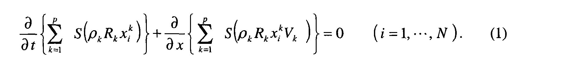
Le code TACITE, on le rappelle, est adapté à suivre les variations de la composition des mélanges d'hydrocarbures. Comme déjà décrit dans les brevets précités du demandeur, il y a une équation de conservation de masse pour chaque pseudo-composant. Il y a aussi une équation de quantité de mouvement et une équation pour l'énergie du mélange. Les équations correspondantes sont rappelées ci-après, après une définition des symboles et notations:
- V vitesse absolue de phase ;
- U vitesse superficielle ;
- R fraction volumétrique par phase ;
- ρ densité de phase ;
- H enthalpie de phase ;
- E énergie interne ;
- P pression du mélange ;
- Tw frottement pariétal ;
- Qw flux de chaleur pariétal entre le pipeline et le milieu environnant ;
- inclinaison du pipeline ;
- g gravité ;
- S section du pipeline ;
- x fraction massique du composant dans une phase donnée ;
- p nombre de phases (de 1 à 3) ;
- N nombre de composants ;
- k indice de phase ;
- i indice de composant ;
- m indice de mélange.
- L'équation d'équilibre de masse pour chaque composant est :
- L'équation d'équilibre de la quantité de mouvement du mélange est :

- L'équation d'équilibre d'énergie du mélange est :

- V absolute phase speed;
- U surface speed;
- R volumetric fraction per phase;
- ρ phase density;
- H phase enthalpy;
- E internal energy;
- P pressure of the mixture;
- T w parietal friction;
- Q w wall heat flow between the pipeline and the surrounding environment;
- tilt of the pipeline;
- g gravity;
- S section of the pipeline;
- x mass fraction of the component in a given phase;
- p number of phases (from 1 to 3);
- N number of components;
- k phase index;
- i component index;
- m mix index.
- The equilibrium mass equation for each component is:
- The equilibrium equation for the momentum of the mixture is:
- The equilibrium energy equation of the mixture is:
Le schéma numérique est conservatif et non dissipatif. Il fournit un bon bilan de masse et d'énergie en tout point de la conduite et à tout instant. Un schéma mixte implicite/explicite est utilisé pour optimiser le temps de calcul et la capacité de suivi des fronts des ondes de taux de vide, ce qui est particulièrement important dans le cas où la configuration du terrain suivi par le pipeline ou sa configuration propre, favorise la formation de bouchons de liquide avec propagation d'ondes de vide dans les deux directions opposées du pipeline, phénomènes que les spécialistes désignent couramment par "terrain slugging" ou "severe slugging". The digital diagram is conservative and not dissipative. It provides a good balance sheet of mass and energy at any point in the pipe and at all times. A mixed scheme implicit / explicit is used to optimize the computation time and the follow-up capacity vacuum rate wave fronts, which is particularly important in the case where the configuration of the terrain followed by the pipeline or its own configuration, promotes the formation of liquid plugs with propagation of vacuum waves in the two opposite directions of the pipeline, phenomena that specialists designate commonly by "terrain slugging" or "severe slugging".
Le code de simulation TACITE comporte un "flash" thermodynamique intégré i.e. un sous-programme intégré de calcul des propriétés thermodynamiques (équilibre liquide-vapeur, composition de chacune des phases) à l'aide d'une équation d'état. Ce flash réalise des calculs d'équilibre thermodynamique di et tri-phasiques pour des mélanges d'hydrocarbures incluant de l'eau. Les équations d'état cubiques de Peng-Robinson (1) et de Soave-Redlich-Kwong (2) sont utilisées pour modéliser les propriétés thermodynamiques à l'équilibre des phases. Ces équations sont définies dans les publications suivantes :
- D.-Y. Peng D.Y. et al, "A new two-constant equation of state", Ind. Eng. Chem. Fund. 15, 59 (1976);
- Soave G., "Equilibrium constants from a modified Redlich-Kwong equation of state", Chem. Eng. Sci. 27, 1197 (1972).
- D.-Y. Peng DY et al, "A new two-constant equation of state", Ind. Eng. Chem. Fund. 15, 59 (1976);
- Soave G., "Equilibrium constants from a modified Redlich-Kwong equation of state", Chem. Eng. Sci. 27, 1197 (1972).
Dans les deux cas, les volumes moléculaires peuvent être corrigés par la
méthode de Péneloux décrite dans la publication suivante :
Péneloux A. et al, "A consistent correction for Redlich-Kwong-Soave
volumes", Fluid Phase Equilibria 8, 7 (1982).In both cases, the molecular volumes can be corrected by the Péneloux method described in the following publication:
Péneloux A. et al, "A consistent correction for Redlich-Kwong-Soave volumes", Fluid Phase Equilibria 8 , 7 (1982).
Le module dit flash assure un suivi précis de la composition des fluides aussi bien dans l'espace que dans le temps, durant toute la simulation.The so-called flash module ensures precise monitoring of the composition of fluids too both in space and in time, throughout the simulation.
Ce suivi compositionnel rend le code TACITE particulièrement apte à prédire avec précision le risque de la formation d'hydrates, comme on le verra par la suite.This compositional monitoring makes the TACITE code particularly apt to predict precisely the risk of the formation of hydrates, as will be seen later.
Le module hydrodynamique calcule le régime d'écoulement, la vitesse de glissement entre phases et les termes de frottement. The hydrodynamic module calculates the flow regime, the speed of sliding between phases and the friction terms.
La méthode selon l'invention permet de détecter en continu en tout point d'une conduite où circule un mélange polyphasique de fluides pétroliers, les conditions thermodynamiques de formation d'hydrates. Elle comporte l'utilisation d'un module hydrodynamique mécanistique et d'un module thermodynamique compositionnel intégré pour définir les propriétés des phases et la résolution d'équations de conservation de la masse, de conservation de la quantité de mouvement et de transfert d'énergie au sein du mélange, en considérant que le mélange de fluides est sensiblement à l'équilibre à chaque instant, que la composition du mélange polyphasique est variable tout le long de la conduite et que la masse de chaque constituant du mélange est définie globalement par une équation de conservation de la masse sans considération de son état de phase. Les fluides pétroliers sont regroupés en un nombre limité de pseudo-composants regroupant chacun certaines fractions d'hydrocarbures.The method according to the invention makes it possible to continuously detect at any point of a pipe in which a multiphase mixture of petroleum fluids circulates, thermodynamic conditions for hydrate formation. It involves the use a mechanistic hydrodynamic module and a thermodynamic module integrated compositional to define phase properties and resolution mass conservation equations, quantity conservation movement and transfer of energy within the mixture, considering that the mixture of fluids is substantially in equilibrium at all times, that the composition of the multiphase mixture is variable along the pipe and the mass of each constituent of the mixture is defined globally by an equation of conservation of the mass regardless of its phase state. Fluids tankers are grouped into a limited number of pseudo-components grouping each certain fractions of hydrocarbons.
La méthode est caractérisée en ce que l'on détecte les conditions thermodynamiques de formation d'hydrates après avoir opéré un regroupement particulier des fluides pétroliers en pseudo-composants de façon à isoler les composants formateurs d'hydrates, avec définition pour chacun d'eux d'une fraction massique et d'un certain nombre de grandeurs physiques caractéristiques, et on applique aux modules thermodynamique et hydrodynamique, des données relatives à ces pseudo-composants sélectionnés de manière à déterminer en tout point la température (Td) de dissociation des hydrates.The method is characterized in that the conditions are detected thermodynamics of hydrate formation after operating a regrouping particularly petroleum fluids in pseudo-components so as to isolate the hydrate-forming components, with definition for each of them of a fraction mass and a number of characteristic physical quantities, and we applies to the thermodynamic and hydrodynamic modules, data relating to these pseudo-components selected so as to determine at all points the hydrate dissociation temperature (Td).
L'invention concerne aussi une méthode pour contrôler en continu et en tout point d'une conduite où circulent des fluides pétroliers polyphasiques, la formation d'hydrates. Elle comporte la détection des conditions thermodynamiques de formation des hydrates comme défini ci-dessus, l'utilisation d'un organe de contrôle pour comparer la température des fluides pétroliers à cette température de dissociation (Td) et l'application commandée par cet organe de contrôle, de mesures destinées à combattre la formation des hydrates.The invention also relates to a method for continuously and completely monitoring point of a pipe where multiphase petroleum fluids circulate, the formation hydrates. It includes the detection of thermodynamic conditions of hydrate formation as defined above, the use of a control organ to compare the temperature of petroleum fluids to this temperature of dissociation (Td) and the application ordered by this control body, of measures intended to combat the formation of hydrates.
Suivant un premier mode de mise en oeuvre, on utilise des moyens de chauffage associés à la conduite pour élever la température des fluides pétroliers au-dessus de la température de dissociation. Dans le cas où la conduite est incluse avec au moins un deuxième conduit dans un tube isolé du milieu extérieur, on utilise le deuxième conduit pour y faire circuler un fluide chaud.According to a first embodiment, means are used to heating associated with the pipe to raise the temperature of petroleum fluids above of the dissociation temperature. In case the pipe is included with at least a second conduit in a tube isolated from the outside environment, we use the second conduit to circulate a hot fluid there.
Suivant un deuxième mode de mise en oeuvre, sur commande de l'organe de contrôle (C), on injecte des inhibiteurs d'hydrates dans la conduite.According to a second mode of implementation, on command of the member of control (C), hydrate inhibitors are injected into the pipe.
D'autres caractéristiques et avantages de la méthode selon l'invention, apparaítront à la lecture de la description ci-après d'un exemple non limitatif de réalisation, en se référant aux dessins annexés où :
- la Fig.1 montre un organigramme comparé des opérations de simulation dans le cadre de l'application du code TACITE selon que l'on étudie ou non le risque de formation d'hydrates ;
- la Fig.2 montre un organigramme de déroulement des opérations de simulation qui se répètent en tous les points d'un maillage de pipeline ;
- la Fig.3 montre schématiquement un mode de contrôle que l'on peut appliquer pour mettre en oeuvre toute intervention visant à combattre la formation d'hydrates ;
- la Fig.4 montre la section transversale d'un tube le long duquel courent plusieurs ensembles de tubes ou lignes de circulation de fluides ;
- la Fig.5 montre une comparaison des températures de dissociation d'hydrates calculées aux températures expérimentales dans le cas du méthane. L'histogramme est établi à partir de 158 points expérimentaux ;
- la Fig.6 montre une comparaison des températures de dissociation d'hydrates calculées aux températures expérimentales dans le cas de l'éthane. L'histogramme est établi à partir de 126 points expérimentaux ;
- la Fig.7 montre une comparaison des températures de dissociation d'hydrates calculées aux températures expérimentales dans le cas du propane. L'histogramme est établi à partir de 93 points expérimentaux ;
- la Fig.8 montre une comparaison des températures de dissociation d'hydrates calculées aux températures expérimentales dans le cas de l'isobutane. L'histogramme est établi à partir de 43 points expérimentaux ;
- la Fig.9 montre une comparaison des températures de dissociation d'hydrates calculées aux températures expérimentales dans le cas du dioxyde de carbone. L'histogramme est établi à partir de 102 points expérimentaux ;
- la Fig.10 montre une comparaison des températures de dissociation d'hydrates calculées aux températures expérimentales dans le cas de l'azote. L'histogramme est établi à partir de 57 points expérimentaux ;
- la Fig.11 montre une comparaison des températures de dissociation d'hydrates calculées aux températures expérimentales dans le cas du sulfure d'hydrogène. L'histogramme est établi à partir de 64 points expérimentaux ;
- la Fig. 12 montre une comparaison des températures de dissociation d'hydrates calculées aux températures expérimentales dans le cas de mélanges d'hydrocarbures. L'histogramme est établi à partir de 55 points expérimentaux provenant de 8 mélanges différents ;
- la Fig.13 montre schématiquement un exemple de raccordement d'un pipeline avec un riser avec un point d'injection de gaz (pour gas lift) ;
- la Fig.14 montre dans un diagramme bidimensionnel longueur de conduite-temps, un exemple de domaine que l'on peut calculer par la méthode d'apparition d'hydrates dans l'agencement de la Fig.13 ;et
- la Fig.15 montre dans un diagramme bidimensionnel pression-température deux courbes locales d'apparition d'hydrates dans les conduites, selon que l'on tient compte ou non d'une modification de la composition du mélange en circulation.
- Fig.1 shows a comparative flowchart of simulation operations in the context of the application of the TACITE code depending on whether or not the risk of hydrate formation is studied;
- Fig.2 shows a flow diagram of the simulation operations which are repeated at all points of a pipeline mesh;
- Fig.3 schematically shows a control mode that can be applied to implement any intervention to combat the formation of hydrates;
- Fig.4 shows the cross section of a tube along which run several sets of tubes or fluid circulation lines;
- Fig. 5 shows a comparison of the hydrate dissociation temperatures calculated with the experimental temperatures in the case of methane. The histogram is established from 158 experimental points;
- Fig. 6 shows a comparison of the hydrate dissociation temperatures calculated with the experimental temperatures in the case of ethane. The histogram is established from 126 experimental points;
- Fig. 7 shows a comparison of the hydrate dissociation temperatures calculated with the experimental temperatures in the case of propane. The histogram is established from 93 experimental points;
- Fig. 8 shows a comparison of the hydrate dissociation temperatures calculated with the experimental temperatures in the case of isobutane. The histogram is established from 43 experimental points;
- Fig. 9 shows a comparison of the hydrate dissociation temperatures calculated with the experimental temperatures in the case of carbon dioxide. The histogram is established from 102 experimental points;
- Fig. 10 shows a comparison of the hydrate dissociation temperatures calculated with the experimental temperatures in the case of nitrogen. The histogram is established from 57 experimental points;
- Fig. 11 shows a comparison of the hydrate dissociation temperatures calculated with the experimental temperatures in the case of hydrogen sulfide. The histogram is established from 64 experimental points;
- Fig. 12 shows a comparison of the hydrate dissociation temperatures calculated with the experimental temperatures in the case of mixtures of hydrocarbons. The histogram is established from 55 experimental points from 8 different mixes;
- Fig. 13 schematically shows an example of connecting a pipeline with a riser with a gas injection point (for gas lift);
- Fig. 14 shows in a two-dimensional pipe length-time diagram, an example of a domain which can be calculated by the hydrate appearance method in the arrangement of Fig. 13; and
- Fig.15 shows in a two-dimensional pressure-temperature diagram two local curves of appearance of hydrates in the pipes, according to whether or not a modification of the composition of the circulating mixture is taken into account.
Les hydrates sont des composés solides constitués de molécules d'hydrocarbures (méthane, éthane, dioxyde de carbone etc.) piégées à haute pression et basse température à l'intérieur de cages approximativement sphériques formées par un réseau cristallin tridimensionnel de molécules d'eau. Cette structure est métastable en l'absence d'hydrocarbures et nécessite un taux de remplissage minimal pour assurer sa stabilisation. A la différence du réseau cristallin de la glace, celui des hydrates peut demeurer stable au-dessus de 0°C.Hydrates are solid compounds made up of molecules hydrocarbons (methane, ethane, carbon dioxide etc.) trapped at high pressure and low temperature inside approximately spherical cages formed by a three-dimensional crystal lattice of water molecules. This structure is metastable in the absence of hydrocarbons and requires a minimum filling rate to ensure its stabilization. Unlike the crystal lattice of ice, that of hydrates can remain stable above 0 ° C.
Des mesures par diffraction aux rayons X réalisées dans les années 50 ont
permis de mettre en évidence deux structures cristallines des hydrates selon la nature
des molécules d'insertion présentes. Dans les deux cas, il s'agit de structures
cubiques organisées en réseaux de petites et grandes cavités. Le tableau ci-après
montre l'occupation possible des différentes cavités selon la nature des molécules
formatrices d'hydrates mises en jeu (+ : occupation possible de la cavité par la
molécule ; - : taille de la cavité insuffisante pour contenir la molécule).
Le réseau de la structure I est de type cubique face centrée. Chaque maille contient 46 molécules d'eau organisées en :
- 2 petites cavités de 3,95 Å de rayon,
- 6 grandes cavités de 4,33 Å de rayon.
- 2 small cavities with a radius of 3.95 Å,
- 6 large cavities with a radius of 4.33 Å.
Le cristal de la structure II a le réseau du diamant. Une maille contient 136 molécules d'eau et 24 cavités :
- 16 petites cavités de rayon 3,91 Å,
- 8 grandes cavités de rayon 4,73 Å.
- 16 small cavities with 3.91 Å radius,
- 8 large cavities with a radius of 4.73 Å.
Une troisième structure, la structure H, a été également identifiée. Son réseau cristallin, de type hexagonal, est constitué de 34 molécules d'eau et de 6 cavités :
- 2 petites cavités de 3,91 Å de rayon,
- 3 cavités intermédiaires d'un rayon de 4,06 Å,
- 1 grande cavité de 5,71 Å de rayon.
- 2 small cavities of 3.91 Å radius,
- 3 intermediate cavities with a radius of 4.06 Å,
- 1 large cavity of 5.71 Å radius.
Cette structure est beaucoup plus rare que les deux précédentes, elle se rencontre principalement dans le cas d'alcanes ou d'alcènes cycliques.This structure is much rarer than the previous two, it is encountered mainly in the case of alkanes or cyclic alkenes.
Tout calcul de prédiction d'hydrates est basé sur le critère d'équilibre de l'eau
en phase hydrate et en phase aqueuse, c'est-à-dire sur l'égalité du potentiel chimique
de l'eau dans la phase hydrate et du potentiel chimique de l'eau dans la phase
aqueuse :
![]()
![]()
Selon la théorie statistique de Van Der Waals et Platteeuw décrite dans la
publication suivante :Van der Waals, J.H., et al., "Clathrate Solutions", Adv. Chem.
Phys., 2, 1, (1959),
le potentiel chimique de l'eau dans la phase hydrate peut s'écrire :

- µ hydrate-vide / eau : potentiel chimique de l'eau dans le réseau cristallin en l'absence de molécule d'hydrocarbure,
- νi : rapport du nombre de cavités de type i (petite ou grande) sur le nombre de molécules d'eau dans un monocristal,
- ik : probabilité pour qu'une cavité de type i soit occupée par une molécule
hydrocarbonée de type k. D'après la théorie de l'adsorption de Langmuir, cette
probabilité peut se calculer par :
où fk est la fugacité du composant k et Cik est le coefficient d'adsorption de Langmuir d'une molécule k dans une cavité de type i.

the chemical potential of water in the hydrate phase can be written:
- µ vacuum hydrate / water: chemical potential of water in the crystal lattice in the absence of a hydrocarbon molecule,
- ν i : ratio of the number of type i cavities (small or large) to the number of water molecules in a single crystal,
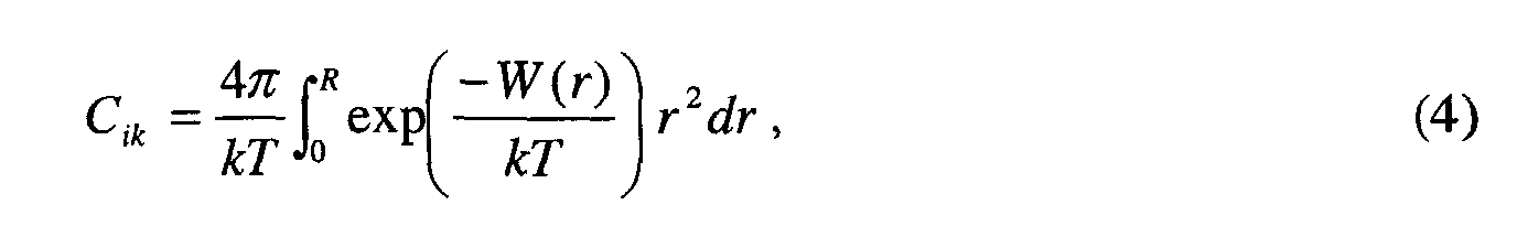
- ik : probability for a type i cavity to be occupied by a type k hydrocarbon molecule. According to Langmuir's adsorption theory, this probability can be calculated by: where f k is the fugacity of the component k and C ik is the Langmuir adsorption coefficient of a molecule k in a cavity of type i.
Les coefficients de Langmuir peuvent être exprimés à partir du potentiel
d'interaction entre les molécules d'eau et les molécules de gaz incluses dans les
cavités de la structure cristalline d'hydrate :
Le potentiel de Lennard-Jones entre deux molécules s'écrit :

- ε: profondeur du puits,
- r : distance entre les centres des molécules,
- σ : diamètre d'exclusion, r tel que W(σ) = 0.
- ε: depth of the well,
- r : distance between the centers of the molecules,
- σ: exclusion diameter, r such that W (σ) = 0.
Le potentiel de Kihara est identique à celui de Lennard-Jones, mais les
molécules sont considérées comme des sphères de rayon non nul. Son expression
analytique est la suivante :

- ε : profondeur du puits,
- σ : tel que W(σ+2a) = 0,
- a : rayon moyen des 2 molécules,
- r : distance entre les centres des molécules.
- ε: depth of the well,
- σ: such that W (σ + 2a) = 0,
- a : mean radius of the 2 molecules,
- r : distance between the centers of the molecules.
Enfin, le potentiel à puits carré est donné par :

Les différents paramètres figurant dans les expressions de ces potentiels sont ajustés sur des données expérimentales d'équilibre d'hydrates.The different parameters appearing in the expressions of these potentials are adjusted on experimental hydrate equilibrium data.
Le potentiel chimique de l'eau dans la phase aqueuse s'écrit :

En égalisant les équations (2) et (8), la condition d'équilibre recherchée (1)
s'écrit :

En fixant la pression, cette équation nous permet d'accéder à la température d'équilibre ou inversement, en fixant la température nous obtenons la pression d'équilibre.By setting the pressure, this equation allows us to access the temperature equilibrium or vice versa, by setting the temperature we get the pressure balance.
Les différents modules de prédiction d'hydrates sont tous basés sur le formalisme décrit ci-dessus. Ces modules vont essentiellement se différencier dans le choix du potentiel d'interaction eau - hydrocarbure, dans le choix de l'équation d'état utilisée pour le calcul des fugacités ainsi que dans le module de calcul de l'activité de l'eau en phase liquide. Dans ce qui suit, nous présentons plus précisément le module que nous avons adapté pour les besoins de TACITE.The different hydrate prediction modules are all based on the formalism described above. These modules will essentially differentiate in the choice of interaction potential water - hydrocarbon, in the choice of the equation report used for the calculation of the fugacities as well as in the module for calculating water activity in liquid phase. In what follows, we present more precisely the module that we have adapted for the needs of TACITE.
Le module de prédiction d'hydrates implémenté dans TACITE s'inspire du module de Munck tel que décrit par Munck, J. et al, "Computations of the formation of gas hydrates", Chem. Eng. Sci 43, 2661 (1988). Il permet de calculer la température de dissociation des hydrates à pression donnée dans le cas d'un gaz, d'un liquide ou d'un mélange gaz - liquide diphasique en contact avec de l'eau liquide.The hydrate prediction module implemented in TACITE is inspired by the Munck module as described by Munck, J. et al, "Computations of the formation of gas hydrates", Chem. Eng. Sci 43, 2661 (1988). It calculates the dissociation temperature of hydrates at a given pressure in the case of a gas, a liquid or a gas - two-phase liquid mixture in contact with liquid water.
Ce module utilise un potentiel W(r) de type puits carré, ce qui conduit à une
expression de la constante de Langmuir du composé k dans une cavité de type i sous
la forme :
Les fugacités des différents constituants présents dans le mélange, formateurs d'hydrates ou non, sont calculées à l'aide de l'équation d'état de Soave-Redlich-Kwong déjà citée. Un tel calcul se fait par l'appel au module de flash à pression et température fixées intégré dans TACITE.The fugacities of the various constituents present in the mixture, formers hydrates or not, are calculated using the Soave-Redlich-Kwong equation of state already cited. Such a calculation is done by calling the pressure flash module and fixed temperatures integrated in TACITE.
Le module de Munck néglige la solubilité dans la phase aqueuse des
hydrocarbures, de l'azote et du sulfure d'hydrogène. En revanche, la solubilité du
dioxyde de carbone dans l'eau ne peut être négligée et est calculée à l'aide de la
constante de Henry du CO2 dans l'eau :
Les valeurs des coefficients utilisés pour le calcul de la constante de Henry du
CO2 figurent dans le tableau ci-après.
La différence de potentiel chimique entre l'eau liquide pure et l'eau dans la
phase hydrate vide (premier membre de l'équation 9), peut s'écrire, moyennant
quelques approximations :

Dans cette équation, Δµ0 représente la différence de potentiel chimique de l'eau dans le réseau hydrate vide et dans l'eau liquide à T 0 = 273,15 K. ΔH 0 est la différence d'enthalpie correspondante, ΔCp la différence de capacité calorifique et ΔV la différence de volume. La pression P 0 est la pression de vapeur à T 0 ; étant donné que P 0 est très petit comparé à P, on utilise P 0 = 0.In this equation, Δ µ 0 represents the difference in chemical potential of water in the empty hydrate network and in liquid water at T 0 = 273.15 K. Δ H 0 is the corresponding enthalpy difference, ΔC p the difference in heat capacity and Δ V the volume difference. The pressure P 0 is the vapor pressure at T 0 ; since P 0 is very small compared to P , we use P 0 = 0.
La dépendance en température du terme PV est moyennée par :
La combinaison des équations (9) et (13) donne l'équation finale (15) :

Dans cette équation les inconnues sont la pression et la température. Nous avons arbitrairement choisi de fixer la pression et de calculer la température d'équilibre des hydrates correspondante. La recherche de cette température, c'est-à-dire la résolution de l'équation (15), s'effectue de manière itérative par une méthode de Newton-Raphson partant d'une température initiale arbitrairement fixée à 0°C. Nous avons vérifié que la valeur de cette initialisation n'influe pas sur le résultat obtenu.In this equation the unknowns are pressure and temperature. We we arbitrarily chose to set the pressure and calculate the temperature corresponding hydrate balance. The search for this temperature, that is to say the resolution of equation (15), is carried out iteratively by a Newton-Raphson method starting from an arbitrarily fixed initial temperature at 0 ° C. We have verified that the value of this initialization does not influence the obtained result.
Nous avons validé le programme sur un ensemble de 700 points d'équilibre expérimentaux issus de 36 références bibliographiques différentes. Les résultats sont présentés sous forme d'histogrammes où figurent en abscisse, l'écart entre la température de dissociation calculée et celle mesurée, et en ordonnée, le pourcentage de points pour lesquels ces écarts de température sont compris entre les limites indiquées en abscisse. Les points expérimentaux utilisés pour réaliser ces histogrammes correspondent à différents couples pression - température.We validated the program on a set of 700 balance points from 36 different bibliographic references. The results are presented in the form of histograms showing the difference between the calculated dissociation temperature and that measured, and on the ordinate, the percentage points for which these temperature differences are between the limits indicated on the abscissa. The experimental points used to carry out these histograms correspond to different pressure-temperature pairs.
Sur les figures 5 à 11, nous comparons ainsi les résultats du calcul avec les données expérimentales dans le cas de divers corps purs : méthane, éthane, propane, isobutane, dioxyde de carbone, azote et sulfure d'hydrogène.In Figures 5 to 11, we compare the results of the calculation with the experimental data in the case of various pure substances: methane, ethane, propane, isobutane, carbon dioxide, nitrogen and hydrogen sulfide.
Nous constatons que sur l'ensemble des corps purs étudiés, le module utilisé donne d'excellentes prédictions des conditions d'équilibre des hydrates. Pour 99% des points, la température est prédite à ±1°C. Dans tous les cas, l'écart maximal entre les températures de dissociation calculées et mesurées ne dépasse pas 1,6°C.We note that on all the pure bodies studied, the module used gives excellent predictions of the hydrate equilibrium conditions. For 99% points, the temperature is predicted at ± 1 ° C. In all cases, the maximum difference between the calculated and measured dissociation temperatures do not exceed 1.6 ° C.
L'histogramme concernant les données de mélanges d'hydrocarbures, gaz naturels ou huiles, est présenté sur la Fig.12. Les données expérimentales utilisées pour calculer cet histogramme proviennent de huit mélanges différents, six de type gaz naturels et deux huiles. On observe à nouveau une très bonne description du comportement de ces systèmes par le module de prédiction utilisé. The histogram concerning the data of mixtures of hydrocarbons, gases natural or oils, is shown in Fig. 12. Experimental data used to calculate this histogram come from eight different mixes, six of type natural gas and two oils. There is again a very good description of the behavior of these systems by the prediction module used.
L'impact se situe au niveau du regroupement des composants de base (lumping). Dans le cas standard, on cherche à en optimiser le nombre de façon à réduire le temps de calcul tout en gardant une bonne représentation des propriétés d'équilibre et des propriétés des phases. Dans le cas où l'on cherche à prédire les hydrates, il faut pouvoir suivre la composition des composants appelés formateurs d'hydrates et donc, ces composants ne doivent pas être regroupés avec d'autres.The impact is on the grouping of basic components (Lumping). In the standard case, we seek to optimize the number so as to reduce the computation time while keeping a good representation of the properties balance and phase properties. In the case where we try to predict the hydrates, you have to be able to follow the composition of the components called trainers hydrates and therefore, these components should not be combined with others.
Outre les données se situant dans les fichiers de type « .PVT », « .MAS » et « .TYP » décrits précisément ci-après, les différentes données d'entrée de TACITE sont regroupées dans 6 fichiers (cf. Fig. 1):
- « .SCE » : description du scénario, c'est à dire de l'évolution dans le temps de la valeur des différentes conditions aux limites (débit d'entrée, pression de sortie, ouverture de vanne,...);
- « .TOP » : description de la topographie de la conduite (élévation de la conduite en fonction de la longueur) ;
- « .GEO»: description de la géométrie de la conduite (diamètre, longueur, porosité) ;
- « .THE » : description des isolations thermiques de la conduite ;
- « .MSH » : description du maillage ;
- « .STO » : description du type de fichier de résultats et de la fréquence de stockage des résultats.
- ".SCE": description of the scenario, ie the evolution over time of the value of the different boundary conditions (inlet flow rate, outlet pressure, valve opening, etc.);
- ".TOP": description of the topography of the pipe (pipe elevation as a function of length);
- ".GEO": description of the geometry of the pipe (diameter, length, porosity);
- ".THE": description of the thermal insulation of the pipe;
- ".MSH": description of the mesh;
- ".STO": description of the type of results file and the frequency of storage of the results.
Le fichier «.PVT» contient autant de lignes que de données thermodynamiques du fluide à indiquer, respectivement :
- un entier qui définit le type d'équation d'état utilisée : 3 pour Peng-Robinson ou 4 pour Soave-Redlich-Kwong.
- un entier qui définit le nombre de phases ; il est mis à 1 et c'est le flash qui détermine leur nombre.
- le nombre de composants.
- Boucle sur les composants avec indication, pour chacun d'eux, de leur :
- masse molaire [kg/mol].
- température critique [K].
- pression critique [Pa].
- volume critique [m3/mol].
- facteur acentrique [-].
- parachor [((N/m)1/4m3/mol)].
- volume molaire standard (inutilisé).
- facteur de correction volumique [m3/mol].
- coefficients d'enthalpie idéale (tableau de 7 coefficients décrits ci-dessous).
- Fin de la boucle.
- la matrice des coefficients d'interaction binaire [-].
- la température de calage 1 [K], Température de calage 2 [K].
- la viscosité cinématique à la température 1 [m2/s], Viscosité cinématique à la température 2 [m2/s].
- an integer that defines the type of state equation used: 3 for Peng-Robinson or 4 for Soave-Redlich-Kwong.
- an integer that defines the number of phases; it is set to 1 and it is the flash which determines their number.
- the number of components.
- Loop on the components with indication, for each of them, of their:
- molar mass [kg / mol].
- critical temperature [K].
- critical pressure [Pa].
- critical volume [m 3 / mol].
- acentric factor [-].
- parachor [((N / m) 1/4 m 3 / mol)].
- standard molar volume (unused).
- volume correction factor [m 3 / mol].
- ideal enthalpy coefficients (table of 7 coefficients described below).
- End of the loop.
- the matrix of binary interaction coefficients [-].
- setting temperature 1 [K], setting temperature 2 [K].
- kinematic viscosity at temperature 1 [m 2 / s], Kinematic viscosity at temperature 2 [m 2 / s].
Ce fichier comporte également un certain nombre de lignes pour indiquer :
- le nombre de composants initiaux.
- la liste du numéro du groupe dans lequel le composant initial correspondant a été mis. L'ordre est celui dans lequel se trouvaient les composants dans le fichier «.INP ».
- le nombre de pseudo-composants.
- les différentes fractions massiques des composants, ordonnées comme dans le fichier «.PVT».
- the number of initial components.
- the list of the number of the group in which the corresponding initial component has been put. The order is that in which the components were in the ".INP" file.
- the number of pseudo-components.
- the different mass fractions of the components, ordered as in the “.PVT” file.
Ce fichier contient autant de lignes que de pseudo-composants définis dans le fichier «.PVT» et les informations sur les composants tiennent compte de l'ordre dans lequel les composants sont rangés dans le fichier «.PVT».This file contains as many lines as pseudo-components defined in the ".PVT" file and component information take order into account in which the components are stored in the ".PVT" file.
La ième ligne concerne l'identificateur de la nature du ième composant.The i th line concerns the identifier of the nature of the i th component.
La convention suivante est retenue :
Le code de simulation TACITE utilise une méthode de résolution numérique
de type à volumes finis pour simuler les écoulements dans les installations de
production, les conduites étant discrétisées par exemple selon la méthode de maillage
décrite dans la demande de brevet FR EN 00/08200 du demandeur.
A tout instant, en tout point du maillage, les calculs de modélisation sont conduits
selon l'organigramme de la Fig.2.
- calculer précisément grâce au module de prédiction d'hydrates, la température Td de dissociation des hydrates (température au-dessous de laquelle si des hydrates se sont formés, ils ne peuvent se dissocier) ;
- d'utiliser un contrôleur C de type PID (Fig.3) pour comparer la température calculée du fluide (Tfluide) à cette température Td de dissociation ; et
- d'agir si cette température de fluide est inférieure à la température de dissociation majorée d'un petit écart (pour anticiper le problème éventuel) sur l'un des moyens de contrôle prévu .
At any time, at any point of the mesh, the modeling calculations are carried out according to the flowchart in Fig. 2.
- calculate precisely using the hydrate prediction module, the hydrate dissociation temperature Td (temperature below which if hydrates are formed, they cannot dissociate);
- using a PID type controller C (Fig. 3) to compare the calculated temperature of the fluid (Tfluid) with this dissociation temperature Td; and
- to act if this fluid temperature is lower than the dissociation temperature increased by a small deviation (to anticipate the possible problem) on one of the control means provided.
Les opérations de lutte contre la formation d'hydrates sont généralement très coûteuses. La modélisation fine permise par la méthode selon l'invention, permet à l'exploitant de connaítre à tout instant les conditions thermodynamiques régnant tout le long du pipeline et donc de déterminer les endroits où les hydrates sont susceptibles de se former. Il est en mesure quand le besoin s'en fait sentir et seulement à ces moments-là, de mettre en oeuvre des actions pour combattre les dépôts d'hydrates. Les nécessités d'intervention sont plus particulièrement critiques en cas d'arrêt momentané de la production ou quand on procède à des injections de gaz dans le mélange en circulation (aux emplacements de « gas lift ») par exemple.Hydrate control operations are generally very costly. The fine modeling allowed by the method according to the invention allows the operator to know at all times the thermodynamic conditions prevailing along the pipeline and therefore determine where the hydrates are likely to form. He is able when the need arises and only at these times, to implement actions to combat the hydrate deposits. The intervention needs are more particularly critical in case of temporary production stoppage or when injections of gas in the circulating mixture (at the "gas lift" locations) for example.
Un premier mode d'action consiste à réchauffer les fluides en circulation de
manière à les amener au-dessus de la température de dissociation d'hydrates que l'on
a prédite, au moins aux endroits de la conduite où le risque est apparu. Les conduites
pétrolières pour la production marine par grands fonds sont généralement incluses
avec d'autres lignes dans une conduite métallique T revêtue extérieurement d'une
couche isolante. Cet ensemble de lignes (désigné par « bundies » par les gens de
l'art) est réparti souvent en plusieurs faisceaux tels que F1, F2 (cf. Fig.4). Chaque
faisceau comporte généralement une ou plusieurs lignes de transport 1, 2, 3 pour
fluides monophasiques ou polyphasiques qui peuvent être rassemblées dans un tube
commun 4 éventuellement recouvert lui-même extérieurement d'une couche isolante.
L'intérieur de chaque tube 4 est rempli le plus souvent d'un fluide monophasique .
L'espace intérieur de la conduite T, entre les différents faisceaux F1, F2, est rempli
par exemple d'une mousse thermiquement isolante 5. L'une des lignes de transport 2,
3 peut être utilisée par exemple pour faire circuler si besoin est, un fluide de
réchauffage.A first mode of action consists in heating the circulating fluids of
way to bring them above the dissociation temperature of hydrates that we
predicted, at least in places of the pipe where the risk appeared. The pipes
petroleum for deep sea production are generally included
with other lines in a metallic pipe T coated on the outside with
insulating layer. This set of lines (referred to as “bundies” by the people of
art) is often divided into several beams such as F1, F2 (see Fig. 4). Each
bundle generally includes one or
Pour modéliser les transferts thermiques entre les conduites pétrolières de l'ensemble de lignes et leur environnement (autres lignes, milieu extérieur) en tenant compte des moyens d'isolation thermique intercalés, on peut se reporter par exemple à la publication suivante :
- Duret, E. et al, "Pipeline bundles model implemented into a multiphase flow model", SPE 62948, SPE Annual Technical Conference and Exhibition, Dallas, Texas, 1-4 October (2000).
- Duret, E. et al, "Pipeline bundles model implemented into a multiphase flow model", SPE 62948, SPE Annual Technical Conference and Exhibition, Dallas, Texas, 1-4 October (2000).
Un deuxième mode d'action consiste à injecter dans les fluides des additifs inhibiteurs de type connu s'opposant à la formation d'hydrates.A second mode of action consists in injecting additives into the fluids known type of inhibitors opposing the formation of hydrates.
Il s'agit d'un système de contrôle basé, non pas sur une mesure fournie par un capteur réel, mais sur une mesure fournie par un capteur dit « logiciel ».It is a control system based, not on a measurement provided by a real sensor, but on a measurement provided by a so-called "software" sensor.
L'utilisation d'un code compositionnel tel que le code TACITE permet en
tout point du pipeline, un calcul exact, à la pression calculée du fluide et pour la
composition locale calculée en cours de simulation, de la température de dissociation
des hydrates, et par conséquent une bien meilleure simulation des risques
d'apparition d'hydrates que des codes où la composition est supposée fixe,
correspondant à celle que l'on injecte à l'entrée de la conduite. On a pu vérifier par
exemple que l'injection de gaz au pied d'un « riser » (technique bien connue des
gens de l'art), modifiait les conditions thermodynamiques locales d'un mélange
donné de fluides pétroliers, au point que l'on pouvait prédire la formation d'hydrates,
alors qu'en supposant une composition fixe du mélange, ce risque n'était
aucunement détecté. Nous illustrons ce point avec la simulation effectuée d'une
injection de gaz au pied d'un riser se raccordant à un pipeline tel que celui
schématisé sur la Fig.13, alimenté par un mélange dont la composition est donnée
dans le tableau ci-dessous.
La simulation est effectuée en considérant que le mélange initial a été modifié par une injection en bas du riser, de méthane favorisant la formationd'hydrates.The simulation is carried out by considering that the initial mixture has been modified by an injection at the bottom of the riser, of methane favoring the formation of hydrates.
Dans un diagramme longueur de conduite-temps, le domaine d'apparition d'hydrates que l'on obtient est schématisé à la Fig.14.In a pipe length-time diagram, the area of appearance hydrates obtained is shown diagrammatically in Fig. 14.
On a calculé et représenté sur le diagramme bidimensionnel pression-temps de la Fig.15, deux courbes locales de formation d'hydrates, l'une (en pointillés) en considérant que la composition n'a pas été altérée par l'injection de méthane, comme le ferait un code de simulation non compositionnel, l'autre (en traits pleins) en tenant compte de la modification de composition intervenue.We calculated and represented on the two-dimensional pressure-time diagram in Fig. 15, two local hydrate formation curves, one (dashed) in whereas the composition was not altered by the injection of methane, as a non-compositional simulation code would do, the other (in solid lines) taking account of the change in composition that occurred.
On vérifie aisément sur la Fig.15, que le point qui y est figuré représentant le couple (pression, température) à l'état final serait considéré à tort comme sans risque puisqu'à droite de la courbe d'hydrates calculée à la composition initiale. Le domaine de risque d'apparition d'hydrates, présenté sur la Fig.14, serait également modifié en raison des variations de composition.It is easy to verify in Fig. 15, that the point on it representing the torque (pressure, temperature) in the final state would be wrongly considered to be without risk since to the right of the hydrate curve calculated at the initial composition. The risk area for the appearance of hydrates, presented in Fig. 14, would also be modified due to variations in composition.
Claims (5)
Applications Claiming Priority (2)
| Application Number | Priority Date | Filing Date | Title |
|---|---|---|---|
| FR0102842 | 2001-03-01 | ||
| FR0102842A FR2821675B1 (en) | 2001-03-01 | 2001-03-01 | METHOD FOR DETECTING AND CONTROLLING THE FORMATION OF HYDRATES AT ANY POINT IN A PIPELINE OR CIRCULATING POLYPHASIC OIL FLUIDS |
Publications (2)
| Publication Number | Publication Date |
|---|---|
| EP1237000A1 true EP1237000A1 (en) | 2002-09-04 |
| EP1237000B1 EP1237000B1 (en) | 2010-04-14 |
Family
ID=8860642
Family Applications (1)
| Application Number | Title | Priority Date | Filing Date |
|---|---|---|---|
| EP02290415A Expired - Lifetime EP1237000B1 (en) | 2001-03-01 | 2002-02-21 | Method for detecting and controlling hydrate formation at every point along a pipe in which polyphasic petroleum fluids flow |
Country Status (7)
| Country | Link |
|---|---|
| US (1) | US6871118B2 (en) |
| EP (1) | EP1237000B1 (en) |
| BR (1) | BR0200499A (en) |
| CA (1) | CA2374089C (en) |
| DE (1) | DE60235933D1 (en) |
| FR (1) | FR2821675B1 (en) |
| NO (1) | NO322148B1 (en) |
Cited By (3)
| Publication number | Priority date | Publication date | Assignee | Title |
|---|---|---|---|---|
| WO2006054076A1 (en) * | 2004-11-16 | 2006-05-26 | Heriot-Watt University | Methods for monitoring hydrate inhibition, and early warning system for hydrate formation |
| FR2917170A1 (en) * | 2007-06-07 | 2008-12-12 | Inst Francais Du Petrole | Water droplet mixture i.e. oil effluent, viscosity determining method for e.g. riser, involves determining relation expressing viscosity of mixture, water content of mixture, gas concentration in oil and speed of shearing of mixture |
| CN104462684A (en) * | 2014-12-02 | 2015-03-25 | 辽宁石油化工大学 | Method for predicting generation of hydrate in nature gas pipeline |
Families Citing this family (21)
| Publication number | Priority date | Publication date | Assignee | Title |
|---|---|---|---|---|
| US6853921B2 (en) | 1999-07-20 | 2005-02-08 | Halliburton Energy Services, Inc. | System and method for real time reservoir management |
| US7584165B2 (en) * | 2003-01-30 | 2009-09-01 | Landmark Graphics Corporation | Support apparatus, method and system for real time operations and maintenance |
| US20050065660A1 (en) * | 2003-09-16 | 2005-03-24 | Jostein Aleksandersen | Method for repairing an oil or gas pipeline |
| US20050076085A1 (en) * | 2003-09-18 | 2005-04-07 | Vulcan Portals Inc. | Method and system for managing email attachments for an electronic device |
| WO2005038409A2 (en) * | 2003-10-17 | 2005-04-28 | Invensys Systems, Inc. | Flow assurance monitoring |
| US7676352B1 (en) | 2004-04-19 | 2010-03-09 | Invensys Systems, Inc. | System and method for efficient computation of simulated thermodynamic property and phase equilibrium characteristics using comprehensive local property models |
| US20050283276A1 (en) * | 2004-05-28 | 2005-12-22 | Prescott Clifford N | Real time subsea monitoring and control system for pipelines |
| CN1310026C (en) * | 2004-10-12 | 2007-04-11 | 中国科学院广州能源研究所 | Method and device for in-site measuring gas hydrate and deposit sediment heat stability containing hydrate |
| US20070032994A1 (en) * | 2005-08-02 | 2007-02-08 | Kimminau Stephen J | System and method of flow assurance in a well |
| CN101371164A (en) * | 2006-01-20 | 2009-02-18 | 界标制图有限公司 | Dynamic Production System Management |
| WO2009023659A1 (en) * | 2007-08-14 | 2009-02-19 | Shell Oil Company | System and methods for continuous, online monitoring of a chemical plant or refinery |
| US8469090B2 (en) * | 2009-12-01 | 2013-06-25 | Schlumberger Technology Corporation | Method for monitoring hydrocarbon production |
| WO2012011831A1 (en) | 2010-07-20 | 2012-01-26 | Siemens Aktiengesellschaft | System and method for determination of desposits in multi-phase fluid flow |
| BR112014003504A2 (en) * | 2011-08-16 | 2017-03-14 | Prad Res & Dev Ltd | system for producing fluids from an underground hydrocarbon reservoir, and system for producing fluids from an underground hydrocarbon reservoir traversed by an injection well and a production well |
| MY185220A (en) * | 2012-12-27 | 2021-04-30 | Halliburton Energy Services Inc | Optical device and method for predicting and mitigating hydrate formation using an integrated computation element |
| GB2553449B8 (en) * | 2015-03-23 | 2021-08-11 | Geoquest Systems Bv | Extended isenthalpic and/or isothermal flash calculation for hydrocarbon componets that are soluble in oil, gas and water |
| NO342457B1 (en) * | 2015-06-22 | 2018-05-22 | Future Subsea As | Wax and / or hydrate inhibitor injection system in subsea, oil and gas facilities |
| EP3510314B1 (en) | 2016-09-09 | 2023-08-09 | nVENT SERVICES GMBH | Automated re-melt control systems |
| CN111157510A (en) * | 2020-01-03 | 2020-05-15 | 浙江工业大学 | In-situ online CO determination2Method and apparatus for solubility in alkanes |
| AU2023437902A1 (en) * | 2023-03-21 | 2025-10-09 | Chevron U.S.A. Inc. | Systems and methods for measuring hydrate deposition within a pipeline |
| CN119849340B (en) * | 2025-03-20 | 2025-07-15 | 中国石油大学(华东) | Three-phase flash evaporation calculation method based on machine learning phase identification model |
Citations (4)
| Publication number | Priority date | Publication date | Assignee | Title |
|---|---|---|---|---|
| FR2687223A1 (en) * | 1992-02-12 | 1993-08-13 | Inst Francais Du Petrole | Device and method for monitoring the variations in consistency of a mixture |
| WO1996032629A1 (en) * | 1995-04-13 | 1996-10-17 | Institut Francais Du Petrole | Apparatus for dynamically measuring the changing properties of a fluid |
| WO1998045692A1 (en) * | 1997-04-05 | 1998-10-15 | Heriot-Watt University | Clathrate hydrate dissociation point detection and measurement |
| US6028992A (en) * | 1996-11-18 | 2000-02-22 | Institut Francais Du Petrole | Method for constituting a model representative of multiphase flows in oil production pipes |
Family Cites Families (5)
| Publication number | Priority date | Publication date | Assignee | Title |
|---|---|---|---|---|
| FR2697264B1 (en) * | 1992-10-23 | 1994-12-30 | Inst Francais Du Petrole | Method for reducing the tendency for hydrates to agglomerate in production effluents. |
| US5550761A (en) * | 1994-02-08 | 1996-08-27 | Institut Francais Du Petrole | Method for modelling multiphase flows in pipelines |
| FR2756045B1 (en) * | 1996-11-18 | 1998-12-24 | Inst Francais Du Petrole | METHOD FOR FORMING A SIMULATION MODEL OF TRANSIENT DIPHASIC FLOWS IN CONDUITS |
| US6155102A (en) * | 1998-08-06 | 2000-12-05 | Alberta Research Council | Method and apparatus for use in determining a property of a multiphase fluid |
| US6656366B1 (en) * | 1999-07-12 | 2003-12-02 | Halliburton Energy Services, Inc. | Method for reducing solids buildup in hydrocarbon streams produced from wells |
-
2001
- 2001-03-01 FR FR0102842A patent/FR2821675B1/en not_active Expired - Fee Related
-
2002
- 2002-02-21 EP EP02290415A patent/EP1237000B1/en not_active Expired - Lifetime
- 2002-02-21 DE DE60235933T patent/DE60235933D1/en not_active Expired - Lifetime
- 2002-02-25 US US10/080,682 patent/US6871118B2/en not_active Expired - Fee Related
- 2002-02-26 CA CA2374089A patent/CA2374089C/en not_active Expired - Fee Related
- 2002-02-28 NO NO20020993A patent/NO322148B1/en not_active IP Right Cessation
- 2002-03-01 BR BR0200499-2A patent/BR0200499A/en not_active Application Discontinuation
Patent Citations (4)
| Publication number | Priority date | Publication date | Assignee | Title |
|---|---|---|---|---|
| FR2687223A1 (en) * | 1992-02-12 | 1993-08-13 | Inst Francais Du Petrole | Device and method for monitoring the variations in consistency of a mixture |
| WO1996032629A1 (en) * | 1995-04-13 | 1996-10-17 | Institut Francais Du Petrole | Apparatus for dynamically measuring the changing properties of a fluid |
| US6028992A (en) * | 1996-11-18 | 2000-02-22 | Institut Francais Du Petrole | Method for constituting a model representative of multiphase flows in oil production pipes |
| WO1998045692A1 (en) * | 1997-04-05 | 1998-10-15 | Heriot-Watt University | Clathrate hydrate dissociation point detection and measurement |
Non-Patent Citations (4)
| Title |
|---|
| CALANGE S ET AL: "ONSET CRYSTALLIZATION TEMPERATURE AND DEPOSIT AMOUNT FOR WAXY CRUDES: EXPERIMENTAL DETREMINATION AND THERMODYNAMIC MODELLING", SPE INTERNATIONAL SYMPOSIUM ON OILFIELD CHEMISTRY, XX, XX, 18 February 1997 (1997-02-18), pages 283 - 290, XP000675714 * |
| DANESH A: "hydrate equilibrium data of methyl cyclopentane with methane or nitrogen", CHEMICAL ENGINEERING RESEARCH AND DESIGN, PART A, INSTITUTION OF CHEMICAL ENGINEERS, XX, vol. 72, 1 March 1994 (1994-03-01), pages 197 - 200, XP002071473, ISSN: 0263-8762 * |
| E. DURET ET AL: "PIPELINE BUNDLES MODEL IMPLEMENTED INTO A MULTIPHASE FLOW MODEL", SOCIETY OF PETROLEUM ENGINEERS INC. 62948, ANNUAL TECHNICAL CONFERENCE AND EXHIBITION DALLAS TEXAS, 1 October 2000 (2000-10-01) - 4 October 2000 (2000-10-04), XP001050377 * |
| HENRIOT V ET AL: "TACITE: CONTRIBUTION OF FLUID COMPOSITION TRACKING ON TRANSIENT MULTIPHASE FLOW SIMULATION", PETROLE ET TECHNIQUES, ASSOCIATION FRANCAISE DES TECHNICIENS DU PETROLE. PARIS, FR, no. SUPPL 408, 1 May 1997 (1997-05-01), pages OTC856301 - 10, XP000699908, ISSN: 0152-5425 * |
Cited By (3)
| Publication number | Priority date | Publication date | Assignee | Title |
|---|---|---|---|---|
| WO2006054076A1 (en) * | 2004-11-16 | 2006-05-26 | Heriot-Watt University | Methods for monitoring hydrate inhibition, and early warning system for hydrate formation |
| FR2917170A1 (en) * | 2007-06-07 | 2008-12-12 | Inst Francais Du Petrole | Water droplet mixture i.e. oil effluent, viscosity determining method for e.g. riser, involves determining relation expressing viscosity of mixture, water content of mixture, gas concentration in oil and speed of shearing of mixture |
| CN104462684A (en) * | 2014-12-02 | 2015-03-25 | 辽宁石油化工大学 | Method for predicting generation of hydrate in nature gas pipeline |
Also Published As
| Publication number | Publication date |
|---|---|
| NO322148B1 (en) | 2006-08-21 |
| CA2374089A1 (en) | 2002-09-01 |
| DE60235933D1 (en) | 2010-05-27 |
| FR2821675A1 (en) | 2002-09-06 |
| NO20020993D0 (en) | 2002-02-28 |
| US20020166818A1 (en) | 2002-11-14 |
| FR2821675B1 (en) | 2003-06-20 |
| EP1237000B1 (en) | 2010-04-14 |
| BR0200499A (en) | 2002-12-31 |
| CA2374089C (en) | 2011-01-11 |
| US6871118B2 (en) | 2005-03-22 |
| NO20020993L (en) | 2002-09-02 |
Similar Documents
| Publication | Publication Date | Title |
|---|---|---|
| EP1237000B1 (en) | Method for detecting and controlling hydrate formation at every point along a pipe in which polyphasic petroleum fluids flow | |
| Sloan et al. | Hydrates: state of the art inside and outside flowlines | |
| Akhfash et al. | Gas hydrate thermodynamic inhibition with MDEA for reduced MEG circulation | |
| Zhang et al. | Capillary pressure effect on hydrocarbon phase behavior in unconventional reservoirs | |
| Zhang et al. | Thermodynamically‐consistent flash calculation in energy industry: from iterative schemes to a unified thermodynamics‐informed neural network | |
| Shagapov et al. | Dynamics of formation and dissociation of gas hydrates in pipelines at the various modes of gas transportation | |
| Yang et al. | Prediction of wax precipitation with new modified regular solution model | |
| Rashid et al. | Evolving a robust approach for accurate prediction of methane hydrate formation temperature in the presence of salt inhibitor | |
| Argo et al. | Commercial deployment of low-dosage hydrate inhibitors in a Southern North Sea 69 km wet-gas subsea pipeline | |
| Góes et al. | Wax appearance and prevention in two-phase flow using the multi-solid and drift-flux model | |
| Sansot et al. | Modeling high‐pressure wax formation in petroleum fluids | |
| Mohammadi et al. | Development of Predictive Techniques for Estimating Liquid Water‐Hydrate Equilibrium of Water‐Hydrocarbon System | |
| Lefebvre et al. | Prediction of flexible pipe annulus composition by numerical modeling: identification of key parameters | |
| Sakurai et al. | Development of a model and simulation tool to predict hydrate growth in flowlines for gas hydrate production | |
| Kabir et al. | Heat-transfer models for mitigating wellbore solids deposition | |
| Musakaev et al. | Mathematical model of the downward two-phase flow of a heat-transfer agent in an injection well | |
| Pramudita et al. | Minimum Miscibility Pressure Calculation for CO2 Injection Flooding Based on Oil PVT Properties | |
| Favero et al. | Simulating the displacement of a heavy oil by a lighter oil in an offshore production line | |
| Volk | Displacement & Mixing in Subsea Jumpers–Experimental Data & CFD Simulations | |
| Wu et al. | Risk prediction of natural gas hydrate formation in subsea wet gas pipelines with monoethylene glycol injection | |
| Razavizadeh et al. | Experimental and modeling investigation of gas hydrate phase equilibrium for methane/propane/n-heptane (MPH) ternary hydrates | |
| Rocha et al. | Modeling wax appearance temperature | |
| Ayirala et al. | Application of a new mechanistic parachor model to predict dynamic gas-oil miscibility in reservoir crude oil-solvent systems | |
| Saidu Mohamed et al. | Restoring Technical Potential of Deep-Water Well Impaired by Hydrate Plug Embedded with Wax Deposit with Improved Characterization and Innovative Chemistry | |
| Otung et al. | A CFD Approach for Predicting Paraffin Deposition in Oilfield Installations |
Legal Events
| Date | Code | Title | Description |
|---|---|---|---|
| PUAI | Public reference made under article 153(3) epc to a published international application that has entered the european phase |
Free format text: ORIGINAL CODE: 0009012 |
|
| AK | Designated contracting states |
Kind code of ref document: A1 Designated state(s): AT BE CH CY DE DK ES FI FR GB GR IE IT LI LU MC NL PT SE TR |
|
| AX | Request for extension of the european patent |
Free format text: AL;LT;LV;MK;RO;SI |
|
| 17P | Request for examination filed |
Effective date: 20030304 |
|
| AKX | Designation fees paid |
Designated state(s): DE GB IT NL |
|
| 17Q | First examination report despatched |
Effective date: 20090622 |
|
| GRAP | Despatch of communication of intention to grant a patent |
Free format text: ORIGINAL CODE: EPIDOSNIGR1 |
|
| GRAS | Grant fee paid |
Free format text: ORIGINAL CODE: EPIDOSNIGR3 |
|
| GRAA | (expected) grant |
Free format text: ORIGINAL CODE: 0009210 |
|
| AK | Designated contracting states |
Kind code of ref document: B1 Designated state(s): DE GB IT NL |
|
| REG | Reference to a national code |
Ref country code: GB Ref legal event code: FG4D Free format text: NOT ENGLISH |
|
| REG | Reference to a national code |
Ref country code: NL Ref legal event code: T3 |
|
| REF | Corresponds to: |
Ref document number: 60235933 Country of ref document: DE Date of ref document: 20100527 Kind code of ref document: P |
|
| PLBE | No opposition filed within time limit |
Free format text: ORIGINAL CODE: 0009261 |
|
| STAA | Information on the status of an ep patent application or granted ep patent |
Free format text: STATUS: NO OPPOSITION FILED WITHIN TIME LIMIT |
|
| 26N | No opposition filed |
Effective date: 20110117 |
|
| PGFP | Annual fee paid to national office [announced via postgrant information from national office to epo] |
Ref country code: IT Payment date: 20110219 Year of fee payment: 10 Ref country code: DE Payment date: 20110315 Year of fee payment: 10 Ref country code: NL Payment date: 20110228 Year of fee payment: 10 |
|
| REG | Reference to a national code |
Ref country code: DE Ref legal event code: R081 Ref document number: 60235933 Country of ref document: DE Owner name: IFP ENERGIES NOUVELLES, FR Free format text: FORMER OWNER: INSTITUT FRANCAIS DU PETROLE, RUEIL-MALMAISON, FR Effective date: 20110331 Ref country code: DE Ref legal event code: R081 Ref document number: 60235933 Country of ref document: DE Owner name: IFP ENERGIES NOUVELLES, FR Free format text: FORMER OWNER: INSTITUT FRANCAIS DU PETROLE, RUEIL-MALMAISON, HAUTS-DE-SEINE, FR Effective date: 20110331 |
|
| PGFP | Annual fee paid to national office [announced via postgrant information from national office to epo] |
Ref country code: GB Payment date: 20110224 Year of fee payment: 10 |
|
| REG | Reference to a national code |
Ref country code: NL Ref legal event code: V1 Effective date: 20120901 |
|
| GBPC | Gb: european patent ceased through non-payment of renewal fee |
Effective date: 20120221 |
|
| PG25 | Lapsed in a contracting state [announced via postgrant information from national office to epo] |
Ref country code: IT Free format text: LAPSE BECAUSE OF NON-PAYMENT OF DUE FEES Effective date: 20120221 |
|
| REG | Reference to a national code |
Ref country code: DE Ref legal event code: R119 Ref document number: 60235933 Country of ref document: DE Effective date: 20120901 |
|
| PG25 | Lapsed in a contracting state [announced via postgrant information from national office to epo] |
Ref country code: GB Free format text: LAPSE BECAUSE OF NON-PAYMENT OF DUE FEES Effective date: 20120221 Ref country code: NL Free format text: LAPSE BECAUSE OF NON-PAYMENT OF DUE FEES Effective date: 20120901 |
|
| PG25 | Lapsed in a contracting state [announced via postgrant information from national office to epo] |
Ref country code: DE Free format text: LAPSE BECAUSE OF NON-PAYMENT OF DUE FEES Effective date: 20120901 |