EP1236996A1 - Structure inspection device - Google Patents
Structure inspection device Download PDFInfo
- Publication number
- EP1236996A1 EP1236996A1 EP00955069A EP00955069A EP1236996A1 EP 1236996 A1 EP1236996 A1 EP 1236996A1 EP 00955069 A EP00955069 A EP 00955069A EP 00955069 A EP00955069 A EP 00955069A EP 1236996 A1 EP1236996 A1 EP 1236996A1
- Authority
- EP
- European Patent Office
- Prior art keywords
- vibration
- spring
- pressure medium
- striking section
- striking
- Prior art date
- Legal status (The legal status is an assumption and is not a legal conclusion. Google has not performed a legal analysis and makes no representation as to the accuracy of the status listed.)
- Withdrawn
Links
Images





Classifications
-
- G—PHYSICS
- G01—MEASURING; TESTING
- G01N—INVESTIGATING OR ANALYSING MATERIALS BY DETERMINING THEIR CHEMICAL OR PHYSICAL PROPERTIES
- G01N29/00—Investigating or analysing materials by the use of ultrasonic, sonic or infrasonic waves; Visualisation of the interior of objects by transmitting ultrasonic or sonic waves through the object
- G01N29/44—Processing the detected response signal, e.g. electronic circuits specially adapted therefor
- G01N29/46—Processing the detected response signal, e.g. electronic circuits specially adapted therefor by spectral analysis, e.g. Fourier analysis or wavelet analysis
-
- G—PHYSICS
- G01—MEASURING; TESTING
- G01M—TESTING STATIC OR DYNAMIC BALANCE OF MACHINES OR STRUCTURES; TESTING OF STRUCTURES OR APPARATUS, NOT OTHERWISE PROVIDED FOR
- G01M7/00—Vibration-testing of structures; Shock-testing of structures
-
- G—PHYSICS
- G01—MEASURING; TESTING
- G01N—INVESTIGATING OR ANALYSING MATERIALS BY DETERMINING THEIR CHEMICAL OR PHYSICAL PROPERTIES
- G01N29/00—Investigating or analysing materials by the use of ultrasonic, sonic or infrasonic waves; Visualisation of the interior of objects by transmitting ultrasonic or sonic waves through the object
- G01N29/04—Analysing solids
- G01N29/045—Analysing solids by imparting shocks to the workpiece and detecting the vibrations or the acoustic waves caused by the shocks
-
- G—PHYSICS
- G01—MEASURING; TESTING
- G01N—INVESTIGATING OR ANALYSING MATERIALS BY DETERMINING THEIR CHEMICAL OR PHYSICAL PROPERTIES
- G01N29/00—Investigating or analysing materials by the use of ultrasonic, sonic or infrasonic waves; Visualisation of the interior of objects by transmitting ultrasonic or sonic waves through the object
- G01N29/36—Detecting the response signal, e.g. electronic circuits specially adapted therefor
- G01N29/42—Detecting the response signal, e.g. electronic circuits specially adapted therefor by frequency filtering or by tuning to resonant frequency
-
- G—PHYSICS
- G01—MEASURING; TESTING
- G01N—INVESTIGATING OR ANALYSING MATERIALS BY DETERMINING THEIR CHEMICAL OR PHYSICAL PROPERTIES
- G01N3/00—Investigating strength properties of solid materials by application of mechanical stress
- G01N3/32—Investigating strength properties of solid materials by application of mechanical stress by applying repeated or pulsating forces
-
- G—PHYSICS
- G01—MEASURING; TESTING
- G01N—INVESTIGATING OR ANALYSING MATERIALS BY DETERMINING THEIR CHEMICAL OR PHYSICAL PROPERTIES
- G01N3/00—Investigating strength properties of solid materials by application of mechanical stress
- G01N3/40—Investigating hardness or rebound hardness
- G01N3/405—Investigating hardness or rebound hardness by determining the vibration frequency of a sensing element in contact with the specimen
-
- G—PHYSICS
- G01—MEASURING; TESTING
- G01N—INVESTIGATING OR ANALYSING MATERIALS BY DETERMINING THEIR CHEMICAL OR PHYSICAL PROPERTIES
- G01N33/00—Investigating or analysing materials by specific methods not covered by groups G01N1/00 - G01N31/00
- G01N33/38—Concrete; Lime; Mortar; Gypsum; Bricks; Ceramics; Glass
- G01N33/383—Concrete or cement
-
- G—PHYSICS
- G01—MEASURING; TESTING
- G01N—INVESTIGATING OR ANALYSING MATERIALS BY DETERMINING THEIR CHEMICAL OR PHYSICAL PROPERTIES
- G01N2203/00—Investigating strength properties of solid materials by application of mechanical stress
- G01N2203/003—Generation of the force
- G01N2203/0032—Generation of the force using mechanical means
- G01N2203/0039—Hammer or pendulum
-
- G—PHYSICS
- G01—MEASURING; TESTING
- G01N—INVESTIGATING OR ANALYSING MATERIALS BY DETERMINING THEIR CHEMICAL OR PHYSICAL PROPERTIES
- G01N2203/00—Investigating strength properties of solid materials by application of mechanical stress
- G01N2203/0058—Kind of property studied
- G01N2203/006—Crack, flaws, fracture or rupture
- G01N2203/0062—Crack or flaws
-
- G—PHYSICS
- G01—MEASURING; TESTING
- G01N—INVESTIGATING OR ANALYSING MATERIALS BY DETERMINING THEIR CHEMICAL OR PHYSICAL PROPERTIES
- G01N2203/00—Investigating strength properties of solid materials by application of mechanical stress
- G01N2203/02—Details not specific for a particular testing method
- G01N2203/026—Specifications of the specimen
- G01N2203/0284—Bulk material, e.g. powders
-
- G—PHYSICS
- G01—MEASURING; TESTING
- G01N—INVESTIGATING OR ANALYSING MATERIALS BY DETERMINING THEIR CHEMICAL OR PHYSICAL PROPERTIES
- G01N2203/00—Investigating strength properties of solid materials by application of mechanical stress
- G01N2203/02—Details not specific for a particular testing method
- G01N2203/06—Indicating or recording means; Sensing means
- G01N2203/0617—Electrical or magnetic indicating, recording or sensing means
-
- G—PHYSICS
- G01—MEASURING; TESTING
- G01N—INVESTIGATING OR ANALYSING MATERIALS BY DETERMINING THEIR CHEMICAL OR PHYSICAL PROPERTIES
- G01N2291/00—Indexing codes associated with group G01N29/00
- G01N2291/01—Indexing codes associated with the measuring variable
- G01N2291/015—Attenuation, scattering
-
- G—PHYSICS
- G01—MEASURING; TESTING
- G01N—INVESTIGATING OR ANALYSING MATERIALS BY DETERMINING THEIR CHEMICAL OR PHYSICAL PROPERTIES
- G01N2291/00—Indexing codes associated with group G01N29/00
- G01N2291/02—Indexing codes associated with the analysed material
- G01N2291/023—Solids
- G01N2291/0232—Glass, ceramics, concrete or stone
-
- G—PHYSICS
- G01—MEASURING; TESTING
- G01N—INVESTIGATING OR ANALYSING MATERIALS BY DETERMINING THEIR CHEMICAL OR PHYSICAL PROPERTIES
- G01N2291/00—Indexing codes associated with group G01N29/00
- G01N2291/02—Indexing codes associated with the analysed material
- G01N2291/028—Material parameters
- G01N2291/02827—Elastic parameters, strength or force
-
- G—PHYSICS
- G01—MEASURING; TESTING
- G01N—INVESTIGATING OR ANALYSING MATERIALS BY DETERMINING THEIR CHEMICAL OR PHYSICAL PROPERTIES
- G01N2291/00—Indexing codes associated with group G01N29/00
- G01N2291/10—Number of transducers
- G01N2291/102—Number of transducers one emitter, one receiver
Definitions
- the present invention relates to an apparatus for detecting abnormalities or defects in the interior of a concrete structure.
- Fig. 17 illustrates a conventional apparatus, disclosed in Japanese Patent Application Laid-Open No. 7-20097 for instance, for detecting the sound pressure level of a hammering or striking sound by means of a sound pressure detector such as a microphone thereby to find an internal defect or flaw based on the sound pressure level thus detected.
- a sound pressure detector such as a microphone
- Fig. 17 2001 designates a concrete product, 2003 a hammer device having a hammer head 2002, and 2005 a fast Fourier transform machine connected with a sound level meter 2004 and a display device 2006.
- Japanese Patent Application Laid-Open No. 7-20097 discloses a method of identifying an internal defect with the level of the sound pressure of a hammering sound detected by a sound level meter.
- the concrete product 2001 is hitted or struck lightly with a fixed impulsive force by using the hammer device 2003 equipped with the hammer head 2002.
- the hammering sound generated at that time is collected by the sound level meter 2004, and converted into an electric signal.
- the hammering sound thus converted into the electric signal is recorded by the fast Fourier transform machine 2005, and output to the display device 2006.
- An impact generated in the concrete product 2001 by striking becomes a vibration on the surface, which vibrates the air at the boundary surface, thereby propagating as a sound.
- This sound is converted into an electric signal through a sound collecting device such as the sound level meter 2004.
- the magnitude and frequency of the vibration generated on the surface are different from those in the case of a sound one without any abnormality, and the magnitude and frequency of the sound generated also differ accordingly.
- the internal defect can be detected by comparing the vibration frequency and the sound pressure level of the impulsive sound converted into the electric signal.
- the vibration generated on the measuring surface can be changed by the striking angle and the shape of the striking surface, and hence the characteristic of the impulsive sound generated might also be changed, thus sometimes causing a wrong diagnosis.
- the level of the striking sound detected could be changed greatly depending upon the distance between the point of striking and the sound collecting device, the direction therebetween, etc., so it is necessary to correct the installation position and the direction of the sound collecting device, or alter the settings of the criterion each time there takes place a change in the distance between the sound collecting device and the striking point.
- the present invention is intended to obviate the problems as referred to above, and has for its object to provide a structure diagnosis apparatus and a structure diagnosis method which are capable of objectively evaluate the internal condition of a concrete structure irrespective of surrounding noise or the shape of a hammer, by placing a vibration detecting sensor in direct contact with a measuring surface so as to directly convert a vibration generated on the measuring surface into a corresponding voltage without the intervention of a medium such as air thereby to quantify the vibration generated on the measuring surface concerned.
- a structure inspection apparatus comprising: a vibration unit for generating an elastic wave in a measuring object of a concrete structure; a vibration detector adapted to be placed in contact with a surface of the measuring object for detecting a component in a predetermined frequency range of an elastic vibration generated on the surface of the measuring object by the vibration unit; and a display device for displaying a maximum amplitude of an output signal of the vibration detector.
- the vibration detector comprises: a weight; a spring having one end thereof connected with a contactor which is adapted to be in contact with the measuring object, and the other end thereof connected with the weight; and a vibration sensor connected with the weight for converting a vibration of the weight into a corresponding electric signal.
- a resonance frequency determined by a mass of the weight and a spring constant of the spring is set to be within the predetermined frequency range, so that a component in the predetermined frequency range of an elastic vibration generated on the surface of the measuring object is detected by the vibration sensor.
- the vibration detector comprises: a spring connected with a contactor which is adapted to be in contact with the measuring object, the spring being made of a metallic material of which permeability is varied according to a bending distortion thereof; a coil arranged around the spring which acts as a core member; and a weight connected with the spring.
- a bending distortion produced in the spring by an elastic vibration generated on the surface of the measuring object is detected by the coil.
- the vibration unit comprises: a striking section for vibrating the measuring object thereby to generate an elastic wave; a coil fixed to the striking section; a diode connected with the coil for permitting a current to flow through the coil only in one direction; and a magnet fixedly arranged near the coil in the surroundings of the striking section for generating a magnetic field in a direction in which the coil vibrates. Damping is caused only in one direction of the vibration of the striking section by means of an electromagnetic interaction between the magnet and the coil.
- the vibration unit comprises: a striking section for generating an elastic wave on the measuring surface; a chamber in which the striking section is accommodated; and a striking section operating mechanism for injecting a pressure medium into the chamber thereby to project the striking section outward from the chamber.
- the striking section operating mechanism generates an elastic wave on the measuring surface by applying thereto a fixed vibration force by means of the striking section.
- the striking section operating mechanism comprises: an injector for injecting a pressure medium into the chamber; and a pressure medium feeding mechanism for supplying a pressure medium to the chamber when a distance between the chamber and the measuring surface becomes a predetermined value.
- the pressure medium feeding mechanism comprises: a gas cylinder for reserving the pressure medium; a pressure regulator for regulating the pressure of the pressure medium in the gas cylinder; a supply switch for supplying the pressure medium in the gas cylinder to the injector through the pressure regulator; and a trigger mechanism for triggering the supply switch when the distance between the chamber and the measuring surface becomes a predetermined value.
- the pressure medium feeding mechanism comprises: a compressor connected with the injector for supplying the pressure medium thereto; a supply switch for supplying the pressure medium in the compressor to the injector; and a trigger mechanism for triggering the supply switch when the distance between the chamber and the measuring surface becomes a predetermined value.
- the pressure medium feeding mechanism further comprises a spring having one end thereof connected with a housing of the vibration unit and the other end thereof connected with the trigger mechanism for urging the trigger mechanism in a direction away from the supply switch.
- the display device comprises: an amplifier having an input terminal connected with the vibration detector and an output terminal; a plurality of comparators each having a first input terminal connected with the output terminal of the amplifier, a second input terminal to which a reference voltage is imposed and an output terminal, the comparators being arranged in parallel with one another and each generating an output from its output terminal when an input voltage at its first input terminal exceeds the reference voltage at its second input terminal; and a plurality of display members connected with the output terminals of the comparators, respectively.
- the reference voltages imposed on the output terminals of the comparators, respectively, are set to different values.
- the predetermined-frequency range of the elastic vibration is several kHz or less.
- a structure diagnosis method for detecting an internal defect in a concrete structure comprising: a first step of generating an elastic wave on a measuring surface of a measuring object by applying a fixed force thereto; a second step of converting a vibration generated on the measuring surface in the first step into a corresponding electric signal thereby to calculate a maximum amplitude of a component in a predetermined frequency range of the electric signal; and a third step of comparing the maximum value of the electric signal with a preset threshold thereby to detect the existence or absence of an internal defect in the structure.
- the predetermined frequency range of the electric signal is several kHz or less.
- the term "internal defect” as used in the present invention represents a part having a crack, a surface peel-off, a so-called honeycomb or the like, generated in the interior of a concrete structure, in which cement is non-uniform with the mixing ratio being lower than a predetermined range to increase the proportion of aggregate and hence decrease the mechanical strength to a value not greater than a predetermined range.
- Fig. 1 is a block diagram illustrating the schematic construction of a structure diagnosis apparatus according to a first embodiment of the present invention.
- the structure diagnosis apparatus according to the first embodiment includes a vibration detector 11 for detecting the vibration of a concrete structure 14, a vibration unit 12 by which vibration is applied to the concrete structure 14, and a display device 13 for displaying the vibration detected by the vibration detector 11.
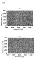
- Figs. 2(a) and 2(b) illustrate the vibration response conditions of the concrete structure 14 displayed by the display device 13, wherein Fig. 2(a) represents the vibration characteristic of a part having an internal defect, and Fig. 2(b) represents the vibration characteristic of a sound or normal part having no internal defect.
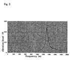
- Fig. 3 illustrates the vibration characteristic of the vibration detector 11.
- Figs. 4(a), Fig. 4(b), Fig. 5(a) and Fig. 5(b) are views illustrating, on a time base, waveforms which are detected by the vibration detector 11 as impulse responses of the concrete structure 14 when an iron ball of a fixed mass is dropped from a fixed height.
- Fig. 4(a) shows the vibration waveform of a part where an internal abnormality exists
- Fig. 4(b) shows the vibration waveform of a sound or normal part.
- Fig. 5(a) and Fig. 5(b) show the waveforms of the impulsive sounds which are generated at that time and detected by a microphone while respectively passing through band-pass filters with the same pass band.
- Fig. 5(a) represents a response observed in the part having the internal defect
- Fig. 5(a) represents a response observed in the sound part having no internal defect.
- Fig. 6 is a block diagram illustrating one example of the construction of the display device 13.
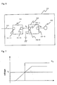
- the display 13 includes an amplifier 51 having an input terminal 51-1 connected with an input signal line 50, a comparator 52 having a signal input terminal 52-1 connected with an output terminal 51-2 of the amplifier 51 and a reference input terminal 52-2 connected with a reference power supply, and an LED 53 connected with an output terminal 52-3 of the comparator 52.
- Fig. 7 illustrates a time base waveform showing the operation of the comparator 52, in which Vin represents an input voltage at the comparison signal input terminal 52-1 of the comparator 52; Vo represents a reference input voltage at the reference input terminal 52-2 of the comparator 52; and Vout represents a voltage at the output terminal 52-3 of the comparator 52, respectively.
- Fig. 8 is a view illustrating the construction of the vibration detector 11.
- the vibration detector 11 is constructed by connecting a contactor 113 with a weight 111 through a spring 112.
- the weight 111 is connected with the spring 112 and is placed in contact with a measuring surface through the contactor 113.
- a vibration/voltage transducer 114 is to convert a vibration into a corresponding voltage, and it is connected with the weight 111 for instance, so that a vibration arriving at the contactor 113 is transmitted therefrom to the vibration/voltage transducer 114 through the spring 112 and the weight 111.
- the vibration thus transmitted to the vibration/voltage transducer 114 is converted into a corresponding electric signal and then output from the vibration detector 11.
- the vibration/voltage transducer 114 is connected with the input signal line 50 of the display device 13, so that an output signal of the vibration/voltage transducer 114 is supplied to the display device 13 through the input signal line 50, whereby the result of the measurement is displayed by the display device 13.
- this vibration system has a resonance frequency fo as represented by the following formula (1).
- fo (1/2 ⁇ ) (k/M) 1/2
- the weight 111 When external vibrations are given to this system, the weight 111 produces a resonance phenomenon at the resonance frequency fo. That is, among the externally input vibrations, a component consistent to the resonance frequency fo is selectively emphasized.
- the vibration/voltage transducer 114 such as an acceleration sensor is fixedly attached to the weight 111, a component of vibrations input from the contactor 113, which is consistent to the resonance frequency fo, is emphasized and output from the vibration detector 11.
- the vibration detector 11 which can selectively detect a vibration component around that frequency and convert it into a corresponding electric signal.
- a mechanical resonance system has a frequency response with a high Q value as compared with an electric potential resonance system, and hence it is possible to achieve a filtering effect of a narrow band. As a result, it is possible to realize a structure inspection apparatus which has excellent signal selectivity and is less subjected to the influence of external noise.
- the vibration unit 12 includes a rod-shaped striking section 131, a spring 132 such as a coil spring connected with the striking section 131, a striking section latching mechanism 133 for latching the striking section 131, a release mechanism 134 rotatably mounted on the striking section latching mechanism 133 and urged by an unillustrated spring or the like to a latch position (Fig.
- a release trigger 135 mounted on the housing of the vibration unit 12 and arranged in opposition to the release mechanism 134, a permanent magnet 136 embedded in the outer peripheral portion of the striking section 131, and a coil 137 mounted on the housing of the vibration unit 12 and arranged adjacent the permanent magnet 136 so as to surround the striking section 131.
- the striking section 131 is attached to the housing of the vibration unit 12 through the spring 132, and the spring 132 with no external force applied thereto has a nature length Lo.
- the striking section 131 latched by the striking section latching mechanism 133 begins to be moved in a direction to contract the spring 132 (Fig. 9(a)). With the external force being continuously kept applied, the striking section 131 and the striking section latching mechanism 133 continue to be moved in the contracting direction of the spring 132, so that the release mechanism 134 mounted on the striking section latching mechanism 133 will come into contact with the release trigger 135 attached to the housing of the vibration unit 12 (Fig. 9 (b)).
- the release trigger 135 liberates or disengages the release mechanism 134 from the striking section 131, whereupon the striking section 131 is pushed out of the vibration unit 12 to strike the measuring surface under the action of the contraction energy of the spring 132 (Fig. 9 (c)).
- the permanent magnet 136 fixedly secured to the housing of the vibration unit 12 generates a magnetic field in the contracting direction of the spring 132, so that a magnetic force acts on the coil 137, which is arranged in the surroundings of the striking section 131 in a direction to intersect the magnetic field generated by the permanent magnet 136, thereby causing the coil 137 and the striking section 131 released from the release mechanism 134 to vibrate together.
- a magnetic force acts on the coil 137, which is arranged in the surroundings of the striking section 131 in a direction to intersect the magnetic field generated by the permanent magnet 136, thereby causing the coil 137 and the striking section 131 released from the release mechanism 134 to vibrate together.
- an induced electromotive force in the coil 137 whereby a current corresponding to the vibration speed is caused to flow through the coil, generating a magnetic flux. Accordingly, there is always generated a magnetic force acting in a direction opposite the direction of vibration, thereby braking the vibration.
- a diode 138 is connected with the coil 137 in such a manner that a current is permitted to flow through the coil 137 when the spring 132 is contracted, but prevented from flowing when the spring 132 is pushed out to expand, as shown in Fig. 10.
- the release mechanism 134 is liberated to permit the striking section 131 to be pushed out of the vibration unit 12
- the striking section 131 is not braked by the coil 137, but can be braked when the striking section 131 starts to move in the contracting direction of the spring after striking.
- the speed of the striking section 131 can be detected by measuring a current, etc., generated in the coil when the striking section 131 is moving. Accordingly, by detecting the timing at which the striking section 131 (hammer) is released and by sampling the output of the vibration detector 11 in synchronization therewith, it is also possible to selectively obtain a signal corresponding to each striking with a reduced influence of external disturbances.
- the vibration detector 11 is brought into contact with an arbitrary point on a surface of the concrete structure 14 which is a measuring object. At this time, when an impact is applied to the surface of the concrete structure 14 (hereinafter referred to as a measuring surface) by means of the vibration unit 12, an elastic vibration is generated on the measuring surface.
- the vibration detector 11 detects the generated vibration and converts it into a corresponding electric signal.
- the vibration detector 11 has a function of outputting the electric signal according to the magnitude of vibration, and here it is shown that the greater the amplitude of the electric signal thus converted, the greater is the vibration generated.
- the electric signal converted by the vibration detector 11 is input to the display device 13.
- the display device 13 is constructed such that it detects the amplitude of the input electric signal and displays the magnitude or dimensions thereof.
- vibration can be generated easily on a surface of the concrete structure by an external impact.
- impulsive or striking energy is applied to the concrete structure from the exterior, there is generated a vibration whose amplitude varies according to the level of deterioration in the mechanical strength.
- Fig. 2(a) represents the vibration characteristic of the part having an internal defect
- Fig. 2 (b) represents the vibration characteristic of the part having no internal defect.
- waveforms after the detected vibration is converted into an electric signal which is in turn subjected to frequency conversion wherein the greater the amplitude level of each waveform, the greater is the amplitude of the vibration, too.
- a high sensitivity characteristic having a center frequency at 1 kHz was given to the vibration detector 11, as shown in Fig. 3, and an iron ball of a fixed mass was dropped from a fixed height, thereby applying a fixed impulsive force to a measuring surface.
- a vibration generated in the measuring surface at this time was detected by the vibration detector 11, it was observed that, as shown in Fig. 4(a), the part in which there exists an internal defect had a large vibration of an amplitude ten or more times greater than that of the part in which there exists no internal defect (Fig. 4(b)).
- the measuring surface is caused to vibrate by an external impact and the vibration generated on the measuring surface is measured directly without the intervention of air, neither external noise nor the resonance sound of the hammer will be transmitted to the measuring surface concerned, and hence these noise and sound do not become impediments to the measurements.
- the vibration of a frequency band specific to a defective portion is selectively detected and a determination is made according to the level of the vibration detected, even where the striking angle of the hammer or the shape of the striking surface changes so that there are generated vibration components hindering the evaluation outside the specific band concerned, such vibration components are attenuated, making it possible to perform a correct determination.
- the display device 13 has a function of displaying an maximum amplitude of an electric signal input thereto, so that a part in which there exists an internal defect can be specified by comparison of the maximum amplitude displayed.
- Fig. 6 is a block diagram illustrating the construction of the display device 13, in which an electric signal converted by the vibration detector 11 is input to the input signal line 50.
- the input signal line 50 is connected with the input terminal 51-1 of the amplifier 51 so that the amplitude of the input signal is amplified by the amplifier 51 with a proper amplification factor, output from the output terminal 51-2, and supplied to the comparison signal input terminal 52-1 of the comparator 52.
- a reference voltage Vo is given to the reference input terminal 52-2 of the comparator 52.
- a display device such as, for instance, the LED 53 is connected with the output terminal 52-3 of the comparator 52.
- the reference voltage Vo of a constant value is always given to the reference input terminal 52-2, so that when the voltage Vin at the comparison signal input terminal 52-1 exceeds the reference voltage Vo, the output terminal 52-3 of the comparator 52 outputs a preset voltage Vout0.
- the output device such as, for instance, the LED 53 is connected with the output terminal 52-3 of the comparator 52, so that when the voltage at the output terminal 52-3 reaches Vout, a current flows to turn the LED 53 on.
- a hammer used by an inspector, a mechanical striking mechanism or the like is adopted as the vibration unit 12, but manual striking has a limitation on the stability of a vibration force generated, and if a mechanism for generating vibration with a constant force by means of a mechanical striking device is adopted, it will be possible to make an accurate determination with further reduced personal dependency or variations.
- the vibration generated on the measuring surface can be directly observed, it is possble to obtain the result of inspection irrespective of inspector's skill or personal dependency or variations by quantifying hammering or striking tests without subject to the influence of diffusion or attenuation of sounds transmitting through a medium such as air, the interference of external noise, etc.
- the vibration detector since the vibration detector has a characteristic of selectively detecting a frequency component of several kHz or less, it is possible to effectively detect the vibration of a frequency of several kHz or less specifically generated in the part where there exists an internal defect likely to produce dull sounds.
- a structure diagnosis apparatus can be achieved which is capable of easily distinguish the part having an internal defect from the part where there exists no internal defect.
- Fig. 11 is a flow chart illustrating a method of diagnosing an internal defect in a concrete structure according to the present invention.
- Fig. 12 is a graph illustrating the amplitude levels of vibrations produced by vibrating a part having an internal defect and a part having no internal defect with application of a fixed force.
- Fig. 13 is a graph illustrating the relation between the amplitude levels of vibrations and the distances (depth) from a measuring surface to internal defects measured in a part where there exist internal defects.
- step S1 it is determined whether a data base concerning the vibration level of a normal part and an abnormal part exists. If such a data base does not exist, an impact is given to the abnormal part where there exists an internal defect and the normal part, respectively, by the vibration unit 12 which generates a constant vibration force (step S2), so that the levels of the vibrations generated in the respective parts are detected (step S3).
- a maximum amplitude level of a component in a predetermined frequency range is calculated (step S4) to construct a data base concerning the vibration levels of the normal part and the abnormal part (step S5). For instance, as illustrated in Fig. 12, the amplitudes of the vibrations measured on the surface of the structure are determined, and the internal state of the structure is checked by coring a measuring point concerned of the structure, so that the results of the measurements are ploted on a graph illustrating the relation therebetween (step S6).
- step S7 an impact is given to a new inspection point or location by means of the vibration unit 12 with a vibration force equal to that in the above-mentioned inspection (step S7).
- the level of a vibration generated is measured (step S8), and the maximum amplitude level of a component in the above-mentioned predetermined frequency range is calculated (step S9), and compared with the threshold previously calculated (step S10).
- step S11 when the level of the measured vibration is greater than the threshold, it is determined that an abnormality exists in the interior of the structure (step S11).
- step S12 when the level of the measured vibration is smaller than the threshold, it is determined that the part inspected is normal (step S12).
- a comparison between the levels of the vibrations generated in the normal part and in the abnormal part having an internal defect shows that they exist separately with a predetermined threshold being made as a boundary.
- Fig. 12 if the threshold for making a discrimination between the normal part and the abnormal part having an internal defect is set to Vo, thereafter, when the part having an internal defect is caused to vibrate by the same impulsive force as before, the level of a signal input to the display device 13 exceeds this threshold Vo, whereby the LED 53 is turned on, making it possible to determine the existence of an internal defect in the interior of the structure.
- the above-mentioned threshold is constructed so as to make discrimination between the normal part and the abnormal (defective) part, the response of the abnormal part varies in the level of vibration generated according to the materials, dimensions and depth of the abnormal part
- Fig. 13 illustrated the result of investigating a relation between the magnitude of vibration and the distance from a surface to a peeled off portion (part where aggregate, etc., is peeled off from the surrounding cement) as one example of an abnormal part, according to a similar procedure, wherein it is turned out that there is a strong correlation therebetween. Then, if the thresholds corresponding to the depths of peeled off portions are set to reference voltages V 1 , V 2 and V 3 of comparators 52 1 , 52 2 and 52 3 , respectively, of Fig. 8, it is possible to find the distances to the internal defects by the number of lit LEDs 53, that is, in four stages in this case.
- a correlation formula representing a relation therebetween is determined experimentally or deductively according to a similar procedure, so that the event concerned is collated with a vibration level newly measured, thus making it possible to detect the internal state of the structure, which could not be evaluated in the past.
- the vibration generated on the measuring surface can be directly observed with application of a fixed level of vibration force, it becomes possible to obtain information on the interior of a structure by comparing the level of the vibration thus measured with the data base measured in advance without subject to the influence of diffusion or attenuation of sounds transmitting through a medium such as air, the interference of external noise, etc.
- Fig. 14 illustrates an example in which a vibration detector 11A is comprised of a plate spring, with the remaining construction of this embodiment being similar to that of the aforementioned first embodiment.
- a weight 111 is connected with a contactor or probe 113 through plate springs 112-2, and a coil 121 is wound around each of the plate springs 112-2 for converting a change in magnetic permeability into a corresponding electric signal.
- a vibration arriving at the contactor 113 is transmitted to the weight 111 through the plate springs 112-2.
- a resonance frequency fo determined by the spring constant k of each plate spring 112-2 and the mass M of the weight 111 is calculated by the above-mentioned formula (1).
- the plate springs 112-2 are made of a material such as a metallic magnetostrictive material, of which permeability changes according to an amount of distortion or strain given thereto.
- a vibration given to the contactor 113 is transmitted to the weight 111, there is generated a bending distortion or strain in the plate springs 112-2, according to which the permeability of the magnetostrictive material changes.
- the coils 121 are arranged in the surroundings of the plate springs 112-2, which are made as cores, respectively, an electromotive force is generated in each coil 121 according to a change in permeability of each core.
- the greater the bending distortion generated in the magnetostrictive material the greater becomes the change in permeability.
- the voltage generated in each coil 121 also increases, so that a voltage or an electric signal can be obtained corresponding to the magnitude of the vibration transmitted to the weight 111.
- the vibration transmitted to the weight 111 is directly detected by means of the plate springs 112-2 connected therewith, it is possible to obtain the vibration detector 11A which has a smaller vibration detection delay, as compared with the case where the vibration/voltage transducer 114 such as an acceleration sensor is fixedly attached to the weight 111 for generating an output. Moreover, it is unnecessary to fixedly attach the vibration/voltage transducer 114 such as an acceleration sensor to the weight 111, so it becomes possible to obtain the vibration detector 11A which is small in size, light in weight, low in cost, and high in sensitivity.
- Fig. 15 illustrates another example of a vibration unit, with the remaining construction of this fourth embodiment being similar to that of the aforementioned first embodiment.
- a vibration unit 12A includes a rod-shaped striking section 141 having one end thereof formed into a ball or spherical shape, a cylindrical chamber 142 having an open end opposed to a measuring surface of a concrete structure 14 and the other end closed, with the striking section 141 being accommodated therein, an air injector 143 arranged at the closed end of the chamber 142 for injecting compressed air into the chamber 142, a gas cylinder 144 connected with the air injector 143 through a pressure regulator 145, a compressed air supply switch 146 provided to the air injector 143, and a trigger mechanism 147 connected with the housing of the vibration unit 12A through the spring 148 and having a switch operation section 149 for operating or triggering the compressed air supply switch 146.
- a clearance between the outer diameter of the striking section 141 and the inner diameter of the chamber 142 is narrow enough so that when compressed air is supplied from the air injector 143 to the chamber 142, the striking section 141 is pushed out by the pressure of the compressed air to project outward from the open end of the chamber 142.
- the compressed air is reserved in the gas cylinder 144 and supplied to the air injector 143 with the pressure thereof being properly adjusted by the pressure regulator 145.
- the trigger mechanism 147 When the open end of the chamber 142 is caused to approach the measuring surface of the concrete structure 14, the trigger mechanism 147 is placed into abutting engagement with the measuring surface so that it is caused to move in a direction to enter the housing of the vibration unit 12A against the urging force of the spring 148. Together with this movement, the switch operation section 149 mounted on the trigger mechanism 147 is brought into abutment against the compressed air supply switch 146 to push it down, whereby the compressed air is supplied from the air injector 143 to the chamber 142, causing the tip end of the striking section 141 to project outward from the open end of the chamber to impinge against or strike the measuring surface of the concrete structure 14.
- the trigger mechanism 147 when the trigger mechanism 147 is moved relative to the housing of the vibration unit 12A to reach a point at which the distance between the chamber 142 and the measuring surface is a predetermined value, the compressed air supply switch 146 is pressed to supply the compressed air.
- the striking section 141 is operated to strike the measuring surface at any time while holding the open end of the chamber 142 at the predetermined distance apart from the measuring surface, so it becomes possible to apply a fixed vibration force to the measuring surface concerned.
- the trigger mechanism 147 is permitted to return to the initial position by separating the vibration mechanism 12 from the measuring surface, so that compressed air can be repeatedly supplied by bringing the vibration unit 12A close to the measuring surface again.
- a return mechanism such as a magnet, a spring or the like may be mounted on the striking section 141 for returning the striking section 141 to the initial position after striking, whereby it is possible to provide the vibration mechanism 12A capable of repeatedly performing striking.
- the vibration unit 12A which is convenient and small-sized, and provide a structure diagnosis apparatus which is capable of repeatedly striking a measuring surface with a constant vibration force. Further, it is also possible to easily control the vibration force by adjusting the pressure of compressed air.
- Fig. 16 illustrates another example of a display device, with the remaining construction of this fifth embodiment being similar to that of the aforementioned first embodiment.
- a display device 13A of this fifth embodiment is provided with a plurality of comparators 52 1 - 52 3 arranged in parallel with each other, so that setting reference voltages for the respective comparators to different values enables the number of lit LEDs 53 1 - 53 3 to be varied according to the amplitude of an input waveform so as to facilitate a staged or step by step display.
- a display device 13A of this fifth embodiment is provided with a plurality of comparators 52 1 - 52 3 arranged in parallel with each other, so that setting reference voltages for the respective comparators to different values enables the number of lit LEDs 53 1 - 53 3 to be varied according to the amplitude of an input waveform so as to facilitate a staged or step by step display.
- the output of the amplifier 51 is dividedly supplied to respective input terminals 52 1 -1 - 52 3 -1 of the comparators 52 1 - 52 3 , so that when an input voltage Vin at each input terminal exceeds the corresponding one of the reference voltages V 1 - V 3 at the reference input terminals, the corresponding one of the LEDs 53 1 - 53 3 is lit according to the above-mentioned logic. That is, by properly adjusting the reference voltages V 1 - V 3 , the number of lit LEDs 53 1 - 53 3 can be varied according to the amplitude of the input waveform.
- the amplitude of the input waveform can be discriminated depending on the number of lit LEDs 53, whereby it becomes possible to detect the presence or absence of internal abnormalities.
- the present invention can be utilized to objectively evaluate the internal condition (internal defects) of a structure such as a concrete structure or the like irrespective of surrounding noise or the shape of a hammer, by placing a vibration sensor in direct contact with a measuring surface so as to directly convert a vibration generated on the measuring surface into a corresponding voltage without the intervention of a medium such as air thereby to quantify the vibration generated on the measuring surface concerned.
Landscapes
- Physics & Mathematics (AREA)
- General Physics & Mathematics (AREA)
- Health & Medical Sciences (AREA)
- Life Sciences & Earth Sciences (AREA)
- Chemical & Material Sciences (AREA)
- Immunology (AREA)
- General Health & Medical Sciences (AREA)
- Biochemistry (AREA)
- Analytical Chemistry (AREA)
- Pathology (AREA)
- Engineering & Computer Science (AREA)
- Signal Processing (AREA)
- Mathematical Physics (AREA)
- Spectroscopy & Molecular Physics (AREA)
- Acoustics & Sound (AREA)
- Ceramic Engineering (AREA)
- Food Science & Technology (AREA)
- Medicinal Chemistry (AREA)
- Investigating Or Analyzing Materials By The Use Of Ultrasonic Waves (AREA)
Abstract
Description
Claims (13)
- A structure inspection apparatus comprising:a vibration unit for generating an elastic wave in a measuring object of a concrete structure;a vibration detector adapted to be placed in contact with a surface of said measuring object for detecting a component in a predetermined frequency range of an elastic vibration generated on the surface of said measuring object by said vibration unit; anda display device for displaying a maximum amplitude of an output signal of said vibration detector.
- The structure inspection apparatus as set forth in claim 1, wherein said vibration detector comprises:wherein a resonance frequency determined by a mass of said weight and a spring constant of said spring is set to be within said predetermined frequency range, so that a component in said predetermined frequency range of an-elastic vibration generated on the surface of said measuring object is detected by said vibration sensor.a weight;a spring having one end thereof connected with a contactor which is adapted to be in contact with said measuring object, and the other end thereof connected with said weight; anda vibration sensor connected with said weight for converting a vibration of said weight into a corresponding electric signal;
- The structure inspection apparatus as set forth in claim 1, wherein said vibration detector comprises:wherein a bending distortion produced in said spring by an elastic vibration generated on the surface of said measuring object is detected by said coil.a spring connected with a contactor which is adapted to be in contact with said measuring object, said spring being made of a metallic material of which permeability is varied according to a bending distortion thereof;a coil arranged around said spring which acts as a core member; anda weight connected with said spring;
- The structure inspection apparatus as set forth in claim 1, wherein said vibration unit comprises:wherein damping is caused only in one direction of the vibration of said striking section by means of an electromagnetic interaction between said magnet and said coil.a striking section for vibrating said measuring object thereby to generate an elastic wave;a coil fixed to said striking section;a diode connected with said coil for permitting a current to flow through said coil only in one direction; anda magnet fixedly arranged near said coil in the surroundings of said striking section for generating a magnetic field in a direction in which said coil vibrates;
- The structure inspection apparatus as set forth in claim 1, wherein said vibration unit comprises:wherein said striking section operating mechanism generates an elastic wave on said measuring surface by applying thereto a fixed vibration force by means of said striking section.a striking section for generating an elastic wave on said measuring surface;a chamber in which said striking section is accommodated; anda striking section operating mechanism for injecting a pressure medium into said chamber thereby to project said striking section outward from said chamber;
- The structure diagnosis apparatus as set forth in claim 5, wherein said striking section operating mechanism comprises:an injector for injecting a pressure medium into said chamber; anda pressure medium feeding mechanism for supplying a pressure medium to said chamber when a distance between said chamber and said measuring surface becomes a predetermined value.
- The structure diagnosis apparatus as set forth in claim 6, wherein said pressure medium feeding mechanism comprises:a gas cylinder for reserving said pressure medium;a pressure regulator for regulating the pressure of said pressure medium in said gas cylinder;a supply switch for supplying said pressure medium in said gas cylinder to said injector through said pressure regulator; anda trigger mechanism for triggering said supply switch when the distance between said chamber and said measuring surface becomes a predetermined value.
- The structure diagnosis apparatus as set forth in claim 6, wherein said pressure medium feeding mechanism comprises:a compressor connected with said injector for supplying said pressure medium thereto;a supply switch for supplying said pressure medium in said compressor to said injector; anda trigger mechanism for triggering said supply switch when the distance between said chamber and said measuring surface becomes a predetermined value.
- The structure diagnosis apparatus as set forth in claim 7 or 8, wherein said pressure medium feeding mechanism further comprises a spring having one end thereof connected with a housing of said vibration unit and the other end thereof connected with said trigger mechanism for urging said trigger mechanism in a direction away from said supply switch.
- The structure diagnosis apparatus as set forth in claim 1, wherein said display device comprises:wherein the reference voltages imposed on the output terminals of said comparators, respectively, are set to different values.an amplifier having an input terminal connected with said vibration detector and an output terminal;a plurality of comparators each having a first input terminal connected with the output terminal of said amplifier, a second input terminal to which a reference voltage is imposed and an output terminal, said comparators being arranged in parallel with one another and each generating an output from its output terminal when an input voltage at its first input terminal exceeds the reference voltage at its second input terminal; anda plurality of display members connected with the output terminals of said comparators, respectively;
- The structure diagnosis apparatus as set forth in claim 1, wherein said predetermined frequency range of said elastic vibration is several kHz or less.
- A structure diagnosis method for detecting an internal defect in a concrete structure, said method comprising:a first step of generating an elastic wave on a measuring surface of a measuring object by applying a fixed force thereto;a second step of converting a vibration generated on said measuring surface in said first step into a corresponding electric signal thereby to calculate a maximum amplitude of a component in a predetermined frequency range of said electric signal; anda third step of comparing the maximum value of said electric signal with a preset threshold thereby to detect the existence or absence of an internal defect in said structure.
- The structure diagnosis method as set forth in claim 12, wherein said predetermined frequency range of said electric signal is several kHz or less.
Applications Claiming Priority (1)
| Application Number | Priority Date | Filing Date | Title |
|---|---|---|---|
| PCT/JP2000/005797 WO2002018927A1 (en) | 2000-08-28 | 2000-08-28 | Structure inspection device |
Publications (2)
| Publication Number | Publication Date |
|---|---|
| EP1236996A1 true EP1236996A1 (en) | 2002-09-04 |
| EP1236996A4 EP1236996A4 (en) | 2008-03-05 |
Family
ID=11736400
Family Applications (1)
| Application Number | Title | Priority Date | Filing Date |
|---|---|---|---|
| EP00955069A Withdrawn EP1236996A4 (en) | 2000-08-28 | 2000-08-28 | STRUCTURE CONTROL DEVICE |
Country Status (4)
| Country | Link |
|---|---|
| US (1) | US6880403B1 (en) |
| EP (1) | EP1236996A4 (en) |
| JP (1) | JP3813580B2 (en) |
| WO (1) | WO2002018927A1 (en) |
Cited By (7)
| Publication number | Priority date | Publication date | Assignee | Title |
|---|---|---|---|---|
| EP1480040A3 (en) * | 2003-05-23 | 2004-12-01 | Asociacion de Investigacion de las Industrias de la Construccion (AIDICO) | Procedure to diagnose the quality in blocks of ornamental rock of large dimensions and devices for its implementation |
| EP1531326A1 (en) * | 2003-11-11 | 2005-05-18 | President of Gunma University | Material testing method |
| EP1843142A3 (en) * | 2006-04-04 | 2010-06-02 | Werner Rogg | Device and method for testing the play of articulations on vehicles |
| CN108732051A (en) * | 2017-04-15 | 2018-11-02 | 张民录 | The method for testing and detecting of thin thin concrete component intensity rebound |
| EP3421964A1 (en) * | 2017-06-30 | 2019-01-02 | Rudi Hachenberg | Method and device for assessing the connection quality of anchor devices |
| US10261052B2 (en) | 2014-03-28 | 2019-04-16 | Nec Corporation | Anchor bolt diagnosing system, method of the same, and program of the same |
| JP2019090637A (en) * | 2017-11-13 | 2019-06-13 | 東急建設株式会社 | Inspection method for structure |
Families Citing this family (26)
| Publication number | Priority date | Publication date | Assignee | Title |
|---|---|---|---|---|
| US7151348B1 (en) * | 2003-04-14 | 2006-12-19 | Matsushita Electric Industrila Co., Ltd. | Motor driving apparatus |
| JP4069016B2 (en) * | 2003-05-28 | 2008-03-26 | 三菱電機株式会社 | Inspection apparatus and inspection method |
| US20070068225A1 (en) | 2005-09-29 | 2007-03-29 | Brown Gregory C | Leak detector for process valve |
| WO2007067084A1 (en) * | 2005-12-06 | 2007-06-14 | Otkrytoe Akzionernoe Obschestvo 'moscow Committee Of Science And Technologies' | Method and system for determining a stability of constructions |
| US20070144260A1 (en) * | 2005-12-27 | 2007-06-28 | Dong Fei | Non-destructive evaluation of particulate filters |
| US7913566B2 (en) * | 2006-05-23 | 2011-03-29 | Rosemount Inc. | Industrial process device utilizing magnetic induction |
| US8898036B2 (en) | 2007-08-06 | 2014-11-25 | Rosemount Inc. | Process variable transmitter with acceleration sensor |
| US7698945B2 (en) * | 2007-11-08 | 2010-04-20 | Caterpillar Inc. | System and method for detecting internal flaws in a particulate filter |
| US8250924B2 (en) | 2008-04-22 | 2012-08-28 | Rosemount Inc. | Industrial process device utilizing piezoelectric transducer |
| US7977924B2 (en) * | 2008-11-03 | 2011-07-12 | Rosemount Inc. | Industrial process power scavenging device and method of deriving process device power from an industrial process |
| JP5666334B2 (en) * | 2011-02-15 | 2015-02-12 | 佐藤工業株式会社 | Quality diagnosis method for concrete structures |
| DE102013201324B4 (en) * | 2013-01-28 | 2024-05-16 | Aktiebolaget Skf | Method for determining a bearing preload |
| CN103630605B (en) * | 2013-11-28 | 2016-01-20 | 中南大学 | A kind of prestress anchorage cable pipeline slip casting detection method |
| JP6422740B2 (en) * | 2014-11-05 | 2018-11-14 | 新川センサテクノロジ株式会社 | Inverse magnetostrictive vibration velocity sensor and measurement method using the same |
| US10186253B2 (en) * | 2015-10-05 | 2019-01-22 | Olympus Corporation | Control device for recording system, and recording system |
| JP6391176B2 (en) * | 2015-11-12 | 2018-09-19 | 国立大学法人 鹿児島大学 | Diagnostic system, mobile device, and diagnostic program |
| JP6688619B2 (en) * | 2016-01-28 | 2020-04-28 | オリエンタル白石株式会社 | Impact device used for impact elastic wave method |
| JP6805445B2 (en) * | 2016-05-12 | 2020-12-23 | 株式会社フジタ | Condition evaluation device for inspection objects |
| KR101865745B1 (en) * | 2016-10-27 | 2018-06-08 | 현대자동차 주식회사 | Joining quality diagnosis device of panel element |
| JP2018200217A (en) * | 2017-05-26 | 2018-12-20 | 国立研究開発法人産業技術総合研究所 | Rattling sound inspection device and rattling sound inspection method |
| JP6773612B2 (en) * | 2017-07-11 | 2020-10-21 | 株式会社東芝 | Acoustic inspection equipment, audio signal acquisition equipment, acoustic inspection system, and acoustic inspection method |
| CN110220659B (en) * | 2018-06-19 | 2021-06-08 | 宜昌明磊建设工程有限公司 | A bridge pillar crack detection device |
| JP2021073459A (en) * | 2021-01-29 | 2021-05-13 | 国立研究開発法人産業技術総合研究所 | Rattling sound inspection device and rattling sound inspection method |
| CN113390962A (en) * | 2021-04-30 | 2021-09-14 | 同济大学 | Implantable concrete member damage monitoring device and method based on directional knocking |
| CN114018705B (en) * | 2021-11-08 | 2022-05-24 | 水利部交通运输部国家能源局南京水利科学研究院 | Visual tracking test system and method for the whole process control of concrete free fracture |
| CN118465060B (en) * | 2024-05-09 | 2024-11-22 | 中国水利水电科学研究院 | Steady-state surface wave transmitting device and forming method for concrete dam crack detection |
Family Cites Families (26)
| Publication number | Priority date | Publication date | Assignee | Title |
|---|---|---|---|---|
| US3580056A (en) * | 1967-10-12 | 1971-05-25 | Hayes Albion Corp | Nondestructive, resonant testing apparatus with magnetic pickup |
| US3859847A (en) * | 1972-09-06 | 1975-01-14 | Westinghouse Electric Corp | Vibration monitoring device using accelerometer to measure displacement |
| US3867836A (en) * | 1973-03-26 | 1975-02-25 | Us Navy | Crack detection apparatus and method |
| IE45963B1 (en) * | 1977-06-27 | 1983-01-12 | Anderson F | A vibration sensing device |
| US4163393A (en) * | 1978-08-04 | 1979-08-07 | The Unites States Of America As Represented By The Secretary Of The Interior | Void detector system |
| US4479389A (en) * | 1982-02-18 | 1984-10-30 | Allied Corporation | Tuned vibration detector |
| CH662886A5 (en) * | 1983-10-12 | 1987-10-30 | Walter Dr Beer | METHOD FOR DETERMINING THE QUALITY OF BALL RACKETS. |
| US4699006A (en) * | 1984-03-19 | 1987-10-13 | The Charles Stark Draper Laboratory, Inc. | Vibratory digital integrating accelerometer |
| US4679033A (en) * | 1986-03-18 | 1987-07-07 | Hwang Shih Ming | Structure of vibration sensor |
| JPH01219555A (en) * | 1988-02-26 | 1989-09-01 | Mitsubishi Petrochem Co Ltd | impact tester |
| US5054606A (en) * | 1988-05-11 | 1991-10-08 | General Kinematics Corporation | Control system for vibratory apparatus |
| JPH0392758A (en) * | 1989-09-05 | 1991-04-17 | Akebono Brake Res & Dev Center Ltd | Product inspection |
| US5152401A (en) * | 1989-10-13 | 1992-10-06 | The United States Of America As Representd By The Secretary Of Agriculture | Agricultural commodity condition measurement |
| US5309149A (en) * | 1992-02-12 | 1994-05-03 | The United States Of America As Represented By The Administrator Of The National Aeronautics And Space Administration | Smart accelerometer |
| JP2500373B2 (en) * | 1993-11-09 | 1996-05-29 | 工業技術院長 | Atomic force microscope and sample observation method in atomic force microscope |
| JP2743314B2 (en) * | 1995-02-16 | 1998-04-22 | 北石産業株式会社 | Vibration detection element and vibration detector |
| JPH08334431A (en) * | 1995-06-09 | 1996-12-17 | Mitsubishi Electric Corp | Non-destructive inspection device |
| JPH10253339A (en) * | 1997-03-06 | 1998-09-25 | Mitsubishi Electric Corp | Measurement method and apparatus using sound waves |
| US5808202A (en) * | 1997-04-04 | 1998-09-15 | Passarelli, Jr.; Frank | Electromagnetic acoustic transducer flaw detection apparatus |
| JP3551033B2 (en) * | 1998-08-28 | 2004-08-04 | 日本精工株式会社 | Apparatus and method for evaluating bearing stiffness |
| WO2000013008A1 (en) * | 1998-09-01 | 2000-03-09 | Mitsubishi Denki Kabushiki Kaisha | Apparatus for nondestructive testing |
| JP2000131290A (en) * | 1998-10-23 | 2000-05-12 | Mitsubishi Electric Corp | Non-destructive inspection equipment for concrete |
| US6298729B1 (en) * | 1999-07-13 | 2001-10-09 | Corning Incorporated | Catalytic converter testing |
| DE19938722B4 (en) * | 1999-08-16 | 2010-10-07 | Prüftechnik Dieter Busch AG | Method and device for analyzing roller bearings in machines |
| US6629448B1 (en) * | 2000-02-25 | 2003-10-07 | Seagate Technology Llc | In-situ testing of a MEMS accelerometer in a disc storage system |
| WO2002016925A1 (en) * | 2000-08-23 | 2002-02-28 | Mitsubishi Denki Kabushiki Kaisha | Non-destructive inspection device |
-
2000
- 2000-08-28 EP EP00955069A patent/EP1236996A4/en not_active Withdrawn
- 2000-08-28 US US10/070,379 patent/US6880403B1/en not_active Expired - Fee Related
- 2000-08-28 WO PCT/JP2000/005797 patent/WO2002018927A1/en not_active Ceased
- 2000-08-28 JP JP2002503072A patent/JP3813580B2/en not_active Expired - Fee Related
Cited By (10)
| Publication number | Priority date | Publication date | Assignee | Title |
|---|---|---|---|---|
| EP1480040A3 (en) * | 2003-05-23 | 2004-12-01 | Asociacion de Investigacion de las Industrias de la Construccion (AIDICO) | Procedure to diagnose the quality in blocks of ornamental rock of large dimensions and devices for its implementation |
| ES2263307A1 (en) * | 2003-05-23 | 2006-12-01 | Asociacion De Investigacion De Industrias De La Construccion Aidico | Procedure to diagnose the quality in blocks of ornamental rock of large dimensions and devices for its implementation |
| ES2263307B1 (en) * | 2003-05-23 | 2007-09-16 | Asociacion De Investigacion De Industrias De La Construccion Aidico | PROCEDURE FOR QUALITY DIAGNOSIS, IN ORNAMENTAL ROCK BLOCKS OF LARGE DIMENSIONS AND DEVICES FOR PUTTING INTO PRACTICE. |
| EP1531326A1 (en) * | 2003-11-11 | 2005-05-18 | President of Gunma University | Material testing method |
| US6918304B2 (en) | 2003-11-11 | 2005-07-19 | Gunma University | Material testing method |
| EP1843142A3 (en) * | 2006-04-04 | 2010-06-02 | Werner Rogg | Device and method for testing the play of articulations on vehicles |
| US10261052B2 (en) | 2014-03-28 | 2019-04-16 | Nec Corporation | Anchor bolt diagnosing system, method of the same, and program of the same |
| CN108732051A (en) * | 2017-04-15 | 2018-11-02 | 张民录 | The method for testing and detecting of thin thin concrete component intensity rebound |
| EP3421964A1 (en) * | 2017-06-30 | 2019-01-02 | Rudi Hachenberg | Method and device for assessing the connection quality of anchor devices |
| JP2019090637A (en) * | 2017-11-13 | 2019-06-13 | 東急建設株式会社 | Inspection method for structure |
Also Published As
| Publication number | Publication date |
|---|---|
| US6880403B1 (en) | 2005-04-19 |
| EP1236996A4 (en) | 2008-03-05 |
| JP3813580B2 (en) | 2006-08-23 |
| WO2002018927A1 (en) | 2002-03-07 |
Similar Documents
| Publication | Publication Date | Title |
|---|---|---|
| US6880403B1 (en) | Structure inspection device | |
| JPWO2002018927A1 (en) | Structural Inspection Equipment | |
| McLaskey et al. | Acoustic emission sensor calibration for absolute source measurements | |
| US4979125A (en) | Non-destructive evaluation of ropes by using transverse impulse vibrational wave method | |
| US6553839B2 (en) | Method for stimulating a sensor and measuring the sensor's output over a frequency range | |
| JPS63186122A (en) | Abnormality diagnosing system for structure | |
| JP6688619B2 (en) | Impact device used for impact elastic wave method | |
| KR20100060257A (en) | Method and apparatus for damage diagnosis of coatings by acoustic emission technique | |
| JP2012168022A (en) | Method for diagnosing quality of concrete-based structure | |
| US4231259A (en) | Method and apparatus for non-destructive evaluation utilizing the internal friction damping (IFD) technique | |
| JP4311680B2 (en) | Structure inspection device | |
| JP7638920B2 (en) | Inspection device and inspection method | |
| JP2005148064A (en) | Device and method for detecting pressure vessel changes or damage during or after pressure test | |
| WO1989004960A1 (en) | Non-destructive evaluation of ropes by using transverse vibrational wave method | |
| JP2003329656A (en) | Degree of adhesion diagnosis method and device for concrete-sprayed slope | |
| JP2002148244A (en) | Concrete structure examining and diagnosing method | |
| Keprt et al. | The determination of uncertainty in the calibration of acoustic emission sensors | |
| JP2002055092A (en) | Structure diagnosis method and structure diagnosis device | |
| JP2018091685A (en) | Inspection apparatus and inspection method | |
| JPH03111735A (en) | Young's modulus automatic measuring device | |
| RU2176396C1 (en) | Process of remote periodic test of conversion factor of piezoelectric accelerometer | |
| Ouarabi et al. | Nonlinear coda wave analysis of hysteretic elastic behavior in strongly scattering media | |
| JP4646012B2 (en) | Nondestructive inspection equipment for concrete structures | |
| JP2001124744A (en) | Inspection apparatus for concrete structure | |
| JP2012168023A (en) | Method for diagnosing quality of concrete-based structure |
Legal Events
| Date | Code | Title | Description |
|---|---|---|---|
| PUAI | Public reference made under article 153(3) epc to a published international application that has entered the european phase |
Free format text: ORIGINAL CODE: 0009012 |
|
| 17P | Request for examination filed |
Effective date: 20020313 |
|
| AK | Designated contracting states |
Kind code of ref document: A1 Designated state(s): AT BE CH CY DE DK ES FI FR GB GR IE IT LI LU MC NL PT SE |
|
| AX | Request for extension of the european patent |
Free format text: AL;LT;LV;MK;RO;SI |
|
| RBV | Designated contracting states (corrected) |
Designated state(s): DE FR GB NL |
|
| RAP1 | Party data changed (applicant data changed or rights of an application transferred) |
Owner name: MATSUHASHI TECHNO RESEARCH CO., LTD Owner name: MITSUBISHI DENKI KABUSHIKI KAISHA |
|
| A4 | Supplementary search report drawn up and despatched |
Effective date: 20080201 |
|
| 17Q | First examination report despatched |
Effective date: 20080611 |
|
| GRAP | Despatch of communication of intention to grant a patent |
Free format text: ORIGINAL CODE: EPIDOSNIGR1 |
|
| RTI1 | Title (correction) |
Free format text: STRUCTURE VIBRATION INSPECTION DEVICE |
|
| STAA | Information on the status of an ep patent application or granted ep patent |
Free format text: STATUS: THE APPLICATION IS DEEMED TO BE WITHDRAWN |
|
| 18D | Application deemed to be withdrawn |
Effective date: 20110615 |