EP1236852B1 - Befestigungsplatte - Google Patents
Befestigungsplatte Download PDFInfo
- Publication number
- EP1236852B1 EP1236852B1 EP20020290359 EP02290359A EP1236852B1 EP 1236852 B1 EP1236852 B1 EP 1236852B1 EP 20020290359 EP20020290359 EP 20020290359 EP 02290359 A EP02290359 A EP 02290359A EP 1236852 B1 EP1236852 B1 EP 1236852B1
- Authority
- EP
- European Patent Office
- Prior art keywords
- plate
- support
- boss
- wafer
- zone
- Prior art date
- Legal status (The legal status is an assumption and is not a legal conclusion. Google has not performed a legal analysis and makes no representation as to the accuracy of the status listed.)
- Expired - Lifetime
Links
- 230000006835 compression Effects 0.000 description 2
- 238000007906 compression Methods 0.000 description 2
- 230000002093 peripheral effect Effects 0.000 description 2
- 229910000831 Steel Inorganic materials 0.000 description 1
- 239000002184 metal Substances 0.000 description 1
- 230000000717 retained effect Effects 0.000 description 1
- 229910000679 solder Inorganic materials 0.000 description 1
- 239000010959 steel Substances 0.000 description 1
- 239000008207 working material Substances 0.000 description 1
Images

Classifications
-
- E—FIXED CONSTRUCTIONS
- E05—LOCKS; KEYS; WINDOW OR DOOR FITTINGS; SAFES
- E05D—HINGES OR SUSPENSION DEVICES FOR DOORS, WINDOWS OR WINGS
- E05D5/00—Construction of single parts, e.g. the parts for attachment
- E05D5/02—Parts for attachment, e.g. flaps
- E05D5/0207—Parts for attachment, e.g. flaps for attachment to vehicles
-
- E—FIXED CONSTRUCTIONS
- E05—LOCKS; KEYS; WINDOW OR DOOR FITTINGS; SAFES
- E05D—HINGES OR SUSPENSION DEVICES FOR DOORS, WINDOWS OR WINGS
- E05D5/00—Construction of single parts, e.g. the parts for attachment
- E05D5/02—Parts for attachment, e.g. flaps
- E05D5/0215—Parts for attachment, e.g. flaps for attachment to profile members or the like
- E05D5/0223—Parts for attachment, e.g. flaps for attachment to profile members or the like with parts, e.g. screws, extending through the profile wall or engaging profile grooves
- E05D5/023—Parts for attachment, e.g. flaps for attachment to profile members or the like with parts, e.g. screws, extending through the profile wall or engaging profile grooves with parts extending through the profile wall
-
- E—FIXED CONSTRUCTIONS
- E05—LOCKS; KEYS; WINDOW OR DOOR FITTINGS; SAFES
- E05Y—INDEXING SCHEME ASSOCIATED WITH SUBCLASSES E05D AND E05F, RELATING TO CONSTRUCTION ELEMENTS, ELECTRIC CONTROL, POWER SUPPLY, POWER SIGNAL OR TRANSMISSION, USER INTERFACES, MOUNTING OR COUPLING, DETAILS, ACCESSORIES, AUXILIARY OPERATIONS NOT OTHERWISE PROVIDED FOR, APPLICATION THEREOF
- E05Y2600/00—Mounting or coupling arrangements for elements provided for in this subclass
- E05Y2600/60—Mounting or coupling members; Accessories therefor
- E05Y2600/63—Retainers
-
- E—FIXED CONSTRUCTIONS
- E05—LOCKS; KEYS; WINDOW OR DOOR FITTINGS; SAFES
- E05Y—INDEXING SCHEME ASSOCIATED WITH SUBCLASSES E05D AND E05F, RELATING TO CONSTRUCTION ELEMENTS, ELECTRIC CONTROL, POWER SUPPLY, POWER SIGNAL OR TRANSMISSION, USER INTERFACES, MOUNTING OR COUPLING, DETAILS, ACCESSORIES, AUXILIARY OPERATIONS NOT OTHERWISE PROVIDED FOR, APPLICATION THEREOF
- E05Y2800/00—Details, accessories and auxiliary operations not otherwise provided for
- E05Y2800/26—Form or shape
-
- F—MECHANICAL ENGINEERING; LIGHTING; HEATING; WEAPONS; BLASTING
- F16—ENGINEERING ELEMENTS AND UNITS; GENERAL MEASURES FOR PRODUCING AND MAINTAINING EFFECTIVE FUNCTIONING OF MACHINES OR INSTALLATIONS; THERMAL INSULATION IN GENERAL
- F16B—DEVICES FOR FASTENING OR SECURING CONSTRUCTIONAL ELEMENTS OR MACHINE PARTS TOGETHER, e.g. NAILS, BOLTS, CIRCLIPS, CLAMPS, CLIPS OR WEDGES; JOINTS OR JOINTING
- F16B5/00—Joining sheets or plates, e.g. panels, to one another or to strips or bars parallel to them
- F16B5/02—Joining sheets or plates, e.g. panels, to one another or to strips or bars parallel to them by means of fastening members using screw-thread
Definitions
- the invention relates to a fixing plate intended to come on the face of a support such as a plate or panel and cooperate with through fasteners such as screws, threaded rods, etc. to clamp said support and participate in fixing one piece on the other face of the support.
- the support in question can be the side opening a door and the part to fix a hinge, such as the hinge described in the document FR 2 784 135.
- the opening is sandwiched between hinge and the face of the wafer opposite to the screw heads.
- a nut comes maintain the whole.
- Another example of a mounting plate is described in document FR 2754008.
- Such flat wafer improves the holding of the assembly during a standardized test called "slump" during which one exercises a load of defined value (80 kg) at the sash lock, and the deformations are measured at the level of the hinge-door connection.
- the object of the invention is to modify the known platelets of in order to improve the resistance of the connection, or even modulate it according to certain directions.
- the invention achieves its goal through a wafer having a generally flat surface likely to rest on the support, and at least a passage for a through fastening element a part of which is retained in support on an area of the plate surrounding the passage, characterized in that said area is formed in a boss of the plate, so as to deport the bearing forces of the fastening element on a larger region of the support.
- the support forces are transmitted by the bottom and perimeter of the boss (not in contact with the support) towards the support zone of the plate on the periphery of the boss, facing support that is in contact with the support.
- This support zone of the plate has a surface area at least equal to and preferably greater than the area of support of the fasteners, so as to distribute and reduce the pressure constraints on the support.
- the very principle of the invention is to deport the support zone the screw head (or similar) on the wall of the support (for example the opening), the essential condition being that the deported zone is of surface at least as important of the support area of the screw head on the part stamped.
- the boss has a flat bottom and is defined by a conical perimeter, preferably inclined at 45 °.
- the wafer has stiffening elements, including curved edges.
- the shape of the wafer can be very varied and include one or several stamped parts, each stamped part can serve as support to one or more screw heads or nuts.
- An advantage is to be able to fasten (for example solder or crimp) the fasteners (screws or nuts) on the board thus ensuring better fixing quality. he however, it is possible to make a tapped hole in the wafer.
- the shape of the stamp can be very varied: polygonal, especially rectangular, elliptical, etc.
- One of the criteria for his choice is the ease of realization of the tool for stamping the wafer.
- a Another criterion is the size of the plate mounted on the opening by relative to its neighborhood (mechanical parts, cables, etc.).
- a another criterion is the shape of the compression cone of the screw that we want get and that comes to extend the conical part of the stamped area.
- the stamped area is rectangular or elliptical, i.e. has a "major axis" and a "minor axis", and includes a screw in its center
- the compression cone is much larger on the wide side only on the narrow side of the stamped area. In other words, the whole formed by the opening and the hinge so fixed can withstand moments more raised around the long axis of the stamped area and weaker moments around the small axis of the stamped area.
- the wafer is made of a working material easily by stamping and resistant to relatively high, for example a metal sheet, in particular of steel.
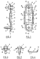
- the substantially rectangular wafer 1 of FIGS. 1 to 5 has a substantially flat face 2 in its middle 3 and on a region peripheral 4 along the bosses 5 and likely to come to rely on a support not shown such as a vehicle opening.
- the two symmetrical bosses 5 are formed by stamping at both ends of the wafer 1, and thus move the support zone away from the fastening elements, constituted for example on the one hand by a screw 6 with a head 7 and on the other hand by a screw 8 with a nut 9.
- the head 7 and the nut 9 rest on the edges of passage openings 10 provided in the bosses 5.
- the head 7 and the nut 9 are welded or crimped to the plate 1.
- the bosses 5 have a flat bottom bordered by a conical connection 11 (for example at 45 °) following the shape of the boss, here in rectangle of which small side is rounded semicircular.
- Raised edges 12 stiffen the plate 1, here around its middle 3.
- the surface of the flat areas support of the wafer on the support (surface of the peripheral region 4 and surface 2) is equal to or greater than the bearing surface of the head 7 and the nut 9 on the bosses 5 of the wafer.
- FIGS. 6 to 8 differs from the first in that the plate 1 is purely rectangular, and framed by two edges longitudinal surveys 12 extending over its entire length.
- One boss 5 is formed on the plate 1 on which the two elements of fastening constituted by a screw 6 with a head 7 and a screw 8 with a nut 9.
- the boss is rectangular in shape and has walls on its perimeter inclined at 45 °.
- the flat surface 2 of support of the plate on its support comprises in particular the parts 4 'separating the boss 5 from the folded edges 12.
Landscapes
- Engineering & Computer Science (AREA)
- Mechanical Engineering (AREA)
- Connection Of Plates (AREA)
- Container, Conveyance, Adherence, Positioning, Of Wafer (AREA)
- Body Structure For Vehicles (AREA)
Claims (7)
- Platte (1), aufweisend eine im Allgemeinen ebene Fläche (2), die fähig ist, sich an einem Träger anzulegen, und mindestens einen Durchgang (10) für ein durchgehendes Befestigungselement (6, 7; 8, 9), von dem ein Teil (7; 9) in Anlage an einem Bereich der Platte gehalten wird, welcher den Durchgang (10) umgibt, dadurch gekennzeichnet, dass der Bereich in einem Vorsprung (5) der Platte (1) in einer Weise gebildet ist, um die Anlagekräfte des Befestigungselements auf einen größeren Bereich des Trägers zu verlagern.
- Platte nach Anspruch 1, dadurch gekennzeichnet, dass der Vorsprung (5) durch Tiefziehen gebildet ist.
- Platte nach irgendeinem der Ansprüche 1 oder 2, dadurch gekennzeichnet, dass der Vorsprung (5) einen ebenen Boden aufweist, der von einem konischen Umfang (11) umgeben ist.
- Platte nach irgendeinem der Ansprüche 1 bis 3, dadurch gekennzeichnet, dass der konische Umfang (11) um in etwa 45° geneigt ist.
- Platte nach irgendeinem der Ansprüche 1 bis 4, dadurch gekennzeichnet, dass der Vorsprung (5) eine große Achse und eine kleine Achse aufweist.
- Platte nach irgendeinem der Ansprüche 1 bis 5, dadurch gekennzeichnet, dass die Platte aufgerichtete Ränder (12) aufweist.
- Platte nach irgendeinem der Ansprüche 1 bis 6, dadurch gekennzeichnet, dass der Anlageteil (7; 9) des durchgehenden Befestigungselements (6, 7; 8, 9) fest mit der Platte (1) verbunden ist.
Applications Claiming Priority (2)
| Application Number | Priority Date | Filing Date | Title |
|---|---|---|---|
| FR0102856A FR2821650B1 (fr) | 2001-03-02 | 2001-03-02 | Plaquette de fixation a cones de compression agrandis |
| FR0102856 | 2001-03-02 |
Publications (2)
| Publication Number | Publication Date |
|---|---|
| EP1236852A1 EP1236852A1 (de) | 2002-09-04 |
| EP1236852B1 true EP1236852B1 (de) | 2005-11-02 |
Family
ID=8860654
Family Applications (1)
| Application Number | Title | Priority Date | Filing Date |
|---|---|---|---|
| EP20020290359 Expired - Lifetime EP1236852B1 (de) | 2001-03-02 | 2002-02-14 | Befestigungsplatte |
Country Status (4)
| Country | Link |
|---|---|
| EP (1) | EP1236852B1 (de) |
| DE (1) | DE60206986T2 (de) |
| ES (1) | ES2247277T3 (de) |
| FR (1) | FR2821650B1 (de) |
Families Citing this family (2)
| Publication number | Priority date | Publication date | Assignee | Title |
|---|---|---|---|---|
| DE102005022813B3 (de) * | 2005-05-12 | 2006-06-14 | Ise Innomotive Systems Europe Gmbh | Kfz-Türscharnier zur gelenkigen Anordnung einer Fahrzeugtür an einer Fahrzeugkarosserie |
| FR2931509B1 (fr) * | 2008-05-23 | 2010-05-28 | Renault Sas | Dispositif et procede de fixation d'un ouvrant sur une caisse d'un vehicule automobile |
Family Cites Families (2)
| Publication number | Priority date | Publication date | Assignee | Title |
|---|---|---|---|---|
| FR2754008B1 (fr) * | 1996-09-27 | 1998-11-27 | Renault | Charnieres de portes ajourees pour automobiles et leur procede de fixation |
| FR2784135B1 (fr) * | 1998-10-02 | 2000-10-27 | Renault | Charniere pour ouvrant de vehicule automobile |
-
2001
- 2001-03-02 FR FR0102856A patent/FR2821650B1/fr not_active Expired - Fee Related
-
2002
- 2002-02-14 EP EP20020290359 patent/EP1236852B1/de not_active Expired - Lifetime
- 2002-02-14 ES ES02290359T patent/ES2247277T3/es not_active Expired - Lifetime
- 2002-02-14 DE DE2002606986 patent/DE60206986T2/de not_active Expired - Fee Related
Also Published As
| Publication number | Publication date |
|---|---|
| EP1236852A1 (de) | 2002-09-04 |
| ES2247277T3 (es) | 2006-03-01 |
| DE60206986D1 (de) | 2005-12-08 |
| FR2821650A1 (fr) | 2002-09-06 |
| FR2821650B1 (fr) | 2003-05-09 |
| DE60206986T2 (de) | 2006-07-27 |
Similar Documents
| Publication | Publication Date | Title |
|---|---|---|
| FR2737107A1 (fr) | Dispositif d'assemblage entre deux parties d'un element prothetique notamment | |
| FR2766442A1 (fr) | Dispositif d'essuie-glace pour vehicule | |
| BE1004911A3 (fr) | Tambour a lames d'une ramasseuse-hacheuse. | |
| FR2586764A1 (fr) | Bride a deblocage rapide | |
| EP0597739A1 (de) | Anordnung zum spielfreien Befestigen von Glasscheiben | |
| FR2919763A1 (fr) | Dispositif pour relier deux armoires pour appareils electriques | |
| EP1236852A1 (de) | Befestigungsplatte | |
| FR2795013A1 (fr) | Outil de centrage et de serrage | |
| FR2799925A1 (fr) | Montant pour une ossature metallique, notamment pour un chassis d'une armoire electrique | |
| FR2736974A1 (fr) | Attache pour la fixation reglable de deux pieces espacees | |
| EP1057552B1 (de) | Kombination von einem Kugelgelenk und einem Dreieckslenker | |
| FR2719009A1 (fr) | Mécanisme d'essuie-glace comportant un dispositif d'articulation perfectionné entre une bielle et une manivelle du mécanisme. | |
| FR2583469A1 (fr) | Ecrou encage | |
| FR2796427A1 (fr) | Dispositif de premontage d'un ecrou pour ensemble de fixation du type vis-ecrou | |
| CA2771683C (fr) | Pont amortissant | |
| EP3741510B1 (de) | Flugzeug mit versteifungen, mindestens einem elektrischen kabelbaum, unterstützungen, die den elektrischen kabelbaum unterstutzen und mit den versteifungen zusammenwirken | |
| BE1010262A5 (fr) | Dispositif de fixation pour rail. | |
| FR3158988A1 (fr) | Dispositif de fixation | |
| FR2571447A1 (fr) | Dispositif pour la fixation de composants electromecaniques a montage " servo " | |
| WO2025168229A1 (fr) | Dispositif de fixation | |
| FR2671147A1 (fr) | Dispositif d'immobilisation de deux pieces assemblees par pression de l'une sur l'autre, en particulier pour vehicule automobile. | |
| FR2809458A1 (fr) | Dispositif de serrage permettant de serrer un injecteur dans un moteur a combustion interne | |
| FR2809473A1 (fr) | Support pour la fixation d'une tablette a une paroi | |
| CA2376753A1 (fr) | Dispositif de fixation d'instruments sur une planche de bord | |
| EP1548295B1 (de) | Anordnung zur Befestigung eines Abgasanlageaufhängeelements an einem Träger am Unterboden eines Kraftfahrzeugs |
Legal Events
| Date | Code | Title | Description |
|---|---|---|---|
| PUAI | Public reference made under article 153(3) epc to a published international application that has entered the european phase |
Free format text: ORIGINAL CODE: 0009012 |
|
| AK | Designated contracting states |
Kind code of ref document: A1 Designated state(s): AT BE CH CY DE DK ES FI FR GB GR IE IT LI LU MC NL PT SE TR |
|
| AX | Request for extension of the european patent |
Free format text: AL;LT;LV;MK;RO;SI |
|
| AKX | Designation fees paid | ||
| REG | Reference to a national code |
Ref country code: DE Ref legal event code: 8566 |
|
| 17P | Request for examination filed |
Effective date: 20030228 |
|
| RBV | Designated contracting states (corrected) |
Designated state(s): BE DE ES GB |
|
| GRAP | Despatch of communication of intention to grant a patent |
Free format text: ORIGINAL CODE: EPIDOSNIGR1 |
|
| GRAS | Grant fee paid |
Free format text: ORIGINAL CODE: EPIDOSNIGR3 |
|
| GRAA | (expected) grant |
Free format text: ORIGINAL CODE: 0009210 |
|
| AK | Designated contracting states |
Kind code of ref document: B1 Designated state(s): BE DE ES GB |
|
| REG | Reference to a national code |
Ref country code: GB Ref legal event code: FG4D Free format text: NOT ENGLISH |
|
| REF | Corresponds to: |
Ref document number: 60206986 Country of ref document: DE Date of ref document: 20051208 Kind code of ref document: P |
|
| GBT | Gb: translation of ep patent filed (gb section 77(6)(a)/1977) |
Effective date: 20060112 |
|
| REG | Reference to a national code |
Ref country code: ES Ref legal event code: FG2A Ref document number: 2247277 Country of ref document: ES Kind code of ref document: T3 |
|
| PLBE | No opposition filed within time limit |
Free format text: ORIGINAL CODE: 0009261 |
|
| STAA | Information on the status of an ep patent application or granted ep patent |
Free format text: STATUS: NO OPPOSITION FILED WITHIN TIME LIMIT |
|
| 26N | No opposition filed |
Effective date: 20060803 |
|
| PGFP | Annual fee paid to national office [announced via postgrant information from national office to epo] |
Ref country code: DE Payment date: 20070216 Year of fee payment: 6 Ref country code: GB Payment date: 20070216 Year of fee payment: 6 |
|
| PGFP | Annual fee paid to national office [announced via postgrant information from national office to epo] |
Ref country code: ES Payment date: 20070227 Year of fee payment: 6 |
|
| PGFP | Annual fee paid to national office [announced via postgrant information from national office to epo] |
Ref country code: BE Payment date: 20070316 Year of fee payment: 6 |
|
| BERE | Be: lapsed |
Owner name: RENAULT S.A.S. Effective date: 20080228 |
|
| GBPC | Gb: european patent ceased through non-payment of renewal fee |
Effective date: 20080214 |
|
| PG25 | Lapsed in a contracting state [announced via postgrant information from national office to epo] |
Ref country code: DE Free format text: LAPSE BECAUSE OF NON-PAYMENT OF DUE FEES Effective date: 20080902 |
|
| PG25 | Lapsed in a contracting state [announced via postgrant information from national office to epo] |
Ref country code: BE Free format text: LAPSE BECAUSE OF NON-PAYMENT OF DUE FEES Effective date: 20080228 |
|
| REG | Reference to a national code |
Ref country code: ES Ref legal event code: FD2A Effective date: 20080215 |
|
| PG25 | Lapsed in a contracting state [announced via postgrant information from national office to epo] |
Ref country code: GB Free format text: LAPSE BECAUSE OF NON-PAYMENT OF DUE FEES Effective date: 20080214 |
|
| PG25 | Lapsed in a contracting state [announced via postgrant information from national office to epo] |
Ref country code: ES Free format text: LAPSE BECAUSE OF NON-PAYMENT OF DUE FEES Effective date: 20080215 |