EP1236630A1 - Mechanical or electric lifting system for automobile - Google Patents
Mechanical or electric lifting system for automobile Download PDFInfo
- Publication number
- EP1236630A1 EP1236630A1 EP01600014A EP01600014A EP1236630A1 EP 1236630 A1 EP1236630 A1 EP 1236630A1 EP 01600014 A EP01600014 A EP 01600014A EP 01600014 A EP01600014 A EP 01600014A EP 1236630 A1 EP1236630 A1 EP 1236630A1
- Authority
- EP
- European Patent Office
- Prior art keywords
- car
- automobile
- screw
- lift
- rods
- Prior art date
- Legal status (The legal status is an assumption and is not a legal conclusion. Google has not performed a legal analysis and makes no representation as to the accuracy of the status listed.)
- Withdrawn
Links
- 230000007246 mechanism Effects 0.000 claims abstract description 6
- 230000003028 elevating effect Effects 0.000 description 2
- 239000004519 grease Substances 0.000 description 1
- 210000003205 muscle Anatomy 0.000 description 1
- 239000004576 sand Substances 0.000 description 1
Images


Classifications
-
- B—PERFORMING OPERATIONS; TRANSPORTING
- B60—VEHICLES IN GENERAL
- B60S—SERVICING, CLEANING, REPAIRING, SUPPORTING, LIFTING, OR MANOEUVRING OF VEHICLES, NOT OTHERWISE PROVIDED FOR
- B60S9/00—Ground-engaging vehicle fittings for supporting, lifting, or manoeuvring the vehicle, wholly or in part, e.g. built-in jacks
- B60S9/02—Ground-engaging vehicle fittings for supporting, lifting, or manoeuvring the vehicle, wholly or in part, e.g. built-in jacks for only lifting or supporting
- B60S9/04—Ground-engaging vehicle fittings for supporting, lifting, or manoeuvring the vehicle, wholly or in part, e.g. built-in jacks for only lifting or supporting mechanically
- B60S9/06—Ground-engaging vehicle fittings for supporting, lifting, or manoeuvring the vehicle, wholly or in part, e.g. built-in jacks for only lifting or supporting mechanically of screw-and-nut type
- B60S9/08—Ground-engaging vehicle fittings for supporting, lifting, or manoeuvring the vehicle, wholly or in part, e.g. built-in jacks for only lifting or supporting mechanically of screw-and-nut type the screw axis being substantially vertical
Definitions
- This invention refers to a lift system situated properly on an automobile and composed of two identical components independent from each other, which are situated on both the left and right side of the automobile. With the help of these two automobile lift components we have the ability to elevate an automobile.
- This invention has the intention of improving the disadvantages above.
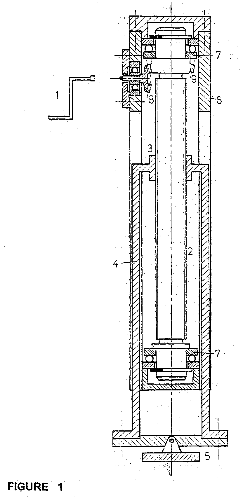
- Figure (1) shows one of the two parts which compose the motor operated part of the car lift.
- the circular motion of the removable wrench (1) is transmitted by the cone shaped toothed wheel (8) to the specially shaped section (9) of the screw movement (2) which brings about itself conic teeth. From there this circular motion changes to a straight up down movement with the help of the screw movement (2) which is a spiral trape-zoid and the screw nut (3) which work together resulting in the elevating or lowering of the automobile.
- the screw nut (3) is situated stably with the two rods with rectangular dimensions (4) which end up in the special footing (5) which has the ability to circle around its central support in a way that it is able to stabilize a car high with safety even on grounds with a slope.
- the rods (4) move up and down as the lifting or lowering of the automobile in to specially designed cavities of the shell of the lift system.
- the screw movement (2) is supported steadily on the shell of the mechanism (6) by two simple ball bearing axial disk shaped moving base.
- figure (2) it shows one of the two identical parts which composes the electric version of the car lift.
- the circular motion of the exit axle of the electric motor (1) is transferred directly to the motion screw (2) which has a spiral trapezoid and with the help of the screw nut (3) and rods (4) the circular motion changes to a straight up down movement resulting in the elevating or lowing of the vehicle.
- the screw nut (3) is situated stably with the two rods with rectangular dimensions (4) which end up in the special footing (5) which has the ability to circle around its central support in a way that is able to stabilize a car high with safety even on grounds with a slope.
- the rods (4) move up and down as the lifting or lowering of the automobile in two specially designed cavities of the shell of the lift system.
- the screw movement (2) is supported steadily on the shell of the mechanism (6) by two simple ball bearing axial disk shaped moving base (7).
Landscapes
- Engineering & Computer Science (AREA)
- Mechanical Engineering (AREA)
- Vehicle Cleaning, Maintenance, Repair, Refitting, And Outriggers (AREA)
Abstract
The lifting of a car can be achieved simply by two identical mechanisms
each of which uses a motion screw (2).
These two mechanisms are independent from each other and are
located on both left and right sides of the car. The motion is
transferred by a crank handle or by an electric motor. The
circular motion is changed into lifting or lowering movement
with the help of the motion screw (2) and of a screw nut (3).
Description
- This invention refers to a lift system situated properly on an automobile and composed of two identical components independent from each other, which are situated on both the left and right side of the automobile. With the help of these two automobile lift components we have the ability to elevate an automobile.
- In order to elevate an automobile in situations such as to change a tire or rise out of sand or mud etc. is now achieved by using a hand held jack, which all automobiles have. In order to correctly and safely use a jack to elevate an automobile we must first : a) have knowledge of how to use it b)have skill and experience in order to place it correctly especially when used on ground with a slope c) substantial muscle strength while working d) enough time which sometimes is precious. Finally we must take into consideration the. possible soiling of hands and clothes from the parts of the jack which are covered with grease.
- For all these reasons the use of a classic jack today results in an unpleasant problem for many people who seek easy and simple solutions having safety in mind.
- This invention has the intention of improving the disadvantages above. One needs to do nothing more than adjust properly the wrench (1) (figure 1) or function the electromotor. Without any effort and avoiding contact with any other part of the system we can achieve the elevation of the vehicle safely even on grounds with a slope. All this is done quickly and effortlessly.
- Figure (1) shows one of the two parts which compose the motor operated part of the car lift. The circular motion of the removable wrench (1) is transmitted by the cone shaped toothed wheel (8) to the specially shaped section (9) of the screw movement (2) which brings about itself conic teeth. From there this circular motion changes to a straight up down movement with the help of the screw movement (2) which is a spiral trape-zoid and the screw nut (3) which work together resulting in the elevating or lowering of the automobile.
- The screw nut (3) is situated stably with the two rods with rectangular dimensions (4) which end up in the special footing (5) which has the ability to circle around its central support in a way that it is able to stabilize a car high with safety even on grounds with a slope.
- The rods (4) move up and down as the lifting or lowering of the automobile in to specially designed cavities of the shell of the lift system.
- The screw movement (2) is supported steadily on the shell of the mechanism (6) by two simple ball bearing axial disk shaped moving base.
- In figure (2) it shows one of the two identical parts which composes the electric version of the car lift. The circular motion of the exit axle of the electric motor (1) is transferred directly to the motion screw (2) which has a spiral trapezoid and with the help of the screw nut (3) and rods (4) the circular motion changes to a straight up down movement resulting in the elevating or lowing of the vehicle.
- The screw nut (3) is situated stably with the two rods with rectangular dimensions (4) which end up in the special footing (5) which has the ability to circle around its central support in a way that is able to stabilize a car high with safety even on grounds with a slope.
- The rods (4) move up and down as the lifting or lowering of the automobile in two specially designed cavities of the shell of the lift system.
- The screw movement (2) is supported steadily on the shell of the mechanism (6) by two simple ball bearing axial disk shaped moving base (7).
Claims (2)
- The car lift is composed of two identical mechanisms each of which is one removable wrench (1) or an electric motor (2). From there 5 the circular motion changes to a straight up down movement with the help of a motion screw (2) which is spiral trapezoid and a screw nut (3)which is steadily connected to the rods (4) resulting in the elevation or lowering of the vehicle.
The car lift is characteristic in that the two mechanisms which it is made up of are independent between them and can work simultaneously or individually. - The lift system according with capability 1 is characteristic in that the two parts of the system are placed on both left and right side of the car and that the special footing (5) and rods (4) have the ability to revolve around its central support in a way that they can stabilize a car safely high even on grounds with a slope.
Applications Claiming Priority (2)
| Application Number | Priority Date | Filing Date | Title |
|---|---|---|---|
| GR2001100094 | 2001-02-20 | ||
| GR20010100094A GR1004000B (en) | 2001-02-20 | 2001-02-20 | Car jack |
Publications (1)
| Publication Number | Publication Date |
|---|---|
| EP1236630A1 true EP1236630A1 (en) | 2002-09-04 |
Family
ID=10944660
Family Applications (1)
| Application Number | Title | Priority Date | Filing Date |
|---|---|---|---|
| EP01600014A Withdrawn EP1236630A1 (en) | 2001-02-20 | 2001-06-01 | Mechanical or electric lifting system for automobile |
Country Status (3)
| Country | Link |
|---|---|
| EP (1) | EP1236630A1 (en) |
| GR (1) | GR1004000B (en) |
| WO (1) | WO2002066304A1 (en) |
Cited By (3)
| Publication number | Priority date | Publication date | Assignee | Title |
|---|---|---|---|---|
| WO2008014745A1 (en) | 2006-07-31 | 2008-02-07 | Haacon Hebetechnik Gmbh | Lifting device |
| US8388023B2 (en) | 2006-07-31 | 2013-03-05 | Haacon Hebetechnik Gmbh | Lifting device |
| US8469340B2 (en) | 2006-07-31 | 2013-06-25 | Haacon Hebetechnik Gmbh | Foot device for supporting a support device or lifting device |
Citations (7)
| Publication number | Priority date | Publication date | Assignee | Title |
|---|---|---|---|---|
| US3680836A (en) * | 1970-10-07 | 1972-08-01 | Joseph A Amelotte | Automatic orientation system |
| US3784160A (en) * | 1972-11-09 | 1974-01-08 | Wildwood Products | Vehicle support system |
| CH644802A5 (en) * | 1981-12-18 | 1984-08-31 | Roger Mettraux | Lifting device for a vehicle |
| CH656867A5 (en) * | 1984-02-07 | 1986-07-31 | Angelo Paparelli | Device for automatically lifting a motor vehicle or the like, without the use of a conventional manual jack |
| US4605086A (en) * | 1983-11-03 | 1986-08-12 | Itshak Marom | Lifting and maneuvering device for motor vehicles |
| WO2000013949A1 (en) * | 1998-09-09 | 2000-03-16 | Roy Spence | Tire changing system with frame mounted jacks and lug wrench |
| FR2794089A3 (en) * | 1999-05-28 | 2000-12-01 | Noberto Raul Lernik | Device for lifting of motor vehicles by means of jacks has two jack units selectively operated independently of each other, with jack unit fitted respectively on one of centre side struts of vehicle |
-
2001
- 2001-02-20 GR GR20010100094A patent/GR1004000B/en unknown
- 2001-06-01 EP EP01600014A patent/EP1236630A1/en not_active Withdrawn
-
2002
- 2002-01-30 WO PCT/GR2002/000003 patent/WO2002066304A1/en not_active Ceased
Patent Citations (7)
| Publication number | Priority date | Publication date | Assignee | Title |
|---|---|---|---|---|
| US3680836A (en) * | 1970-10-07 | 1972-08-01 | Joseph A Amelotte | Automatic orientation system |
| US3784160A (en) * | 1972-11-09 | 1974-01-08 | Wildwood Products | Vehicle support system |
| CH644802A5 (en) * | 1981-12-18 | 1984-08-31 | Roger Mettraux | Lifting device for a vehicle |
| US4605086A (en) * | 1983-11-03 | 1986-08-12 | Itshak Marom | Lifting and maneuvering device for motor vehicles |
| CH656867A5 (en) * | 1984-02-07 | 1986-07-31 | Angelo Paparelli | Device for automatically lifting a motor vehicle or the like, without the use of a conventional manual jack |
| WO2000013949A1 (en) * | 1998-09-09 | 2000-03-16 | Roy Spence | Tire changing system with frame mounted jacks and lug wrench |
| FR2794089A3 (en) * | 1999-05-28 | 2000-12-01 | Noberto Raul Lernik | Device for lifting of motor vehicles by means of jacks has two jack units selectively operated independently of each other, with jack unit fitted respectively on one of centre side struts of vehicle |
Cited By (5)
| Publication number | Priority date | Publication date | Assignee | Title |
|---|---|---|---|---|
| WO2008014745A1 (en) | 2006-07-31 | 2008-02-07 | Haacon Hebetechnik Gmbh | Lifting device |
| DE102006035915A1 (en) * | 2006-07-31 | 2008-02-14 | Haacon Hebetechnik Gmbh | lifting device |
| US8388023B2 (en) | 2006-07-31 | 2013-03-05 | Haacon Hebetechnik Gmbh | Lifting device |
| US8408522B2 (en) | 2006-07-31 | 2013-04-02 | Haacon Hebetechnik Gmbh | Lifting device |
| US8469340B2 (en) | 2006-07-31 | 2013-06-25 | Haacon Hebetechnik Gmbh | Foot device for supporting a support device or lifting device |
Also Published As
| Publication number | Publication date |
|---|---|
| WO2002066304A1 (en) | 2002-08-29 |
| GR1004000B (en) | 2002-09-19 |
Similar Documents
| Publication | Publication Date | Title |
|---|---|---|
| US8052125B2 (en) | Motor drive for a camper jack | |
| CN104890441B (en) | Steering lock for castor | |
| EP1236630A1 (en) | Mechanical or electric lifting system for automobile | |
| EP2462011B1 (en) | Landing gear | |
| CN209098109U (en) | A kind of rotatable lift up of steel structure device | |
| CN1651291A (en) | Height adjustable support for semi-trailer or like | |
| US7845447B2 (en) | System and methods for adjustment of vehicle bodies | |
| JP4709953B2 (en) | Stair lift | |
| US7392995B2 (en) | Driving device for wheels | |
| EP1707467A3 (en) | Low-lifting industrial truck | |
| DE102014006735B4 (en) | Shopping Trolley | |
| JP2006122641A (en) | Wheelchair lifting device | |
| US3785618A (en) | Vehicle jack | |
| CN207537047U (en) | A kind of machinery rocker-arm jack | |
| CN215826686U (en) | Support assembly for semitrailer | |
| CN110091840A (en) | Manual omnidirectional movement controls automobile mobile device to wheel | |
| CN114987631A (en) | Height adjusting device and vehicle | |
| CN212289390U (en) | Axle with variable-length structure | |
| CN210002913U (en) | net rack engineering sliding installation platform | |
| EP1775196A3 (en) | Steering assembly for work vehicles, particularly lift trucks, tractors, trailers and/or the like | |
| CN110091839A (en) | Lateral moving device for automobile is controlled to wheel manually | |
| CN2201302Y (en) | Automobile lifting apparatus | |
| RU33071U1 (en) | JACK FOR CAR | |
| CN107725737B (en) | Automatic separation type gearbox | |
| EP0321164A1 (en) | Vehicle jack |
Legal Events
| Date | Code | Title | Description |
|---|---|---|---|
| PUAI | Public reference made under article 153(3) epc to a published international application that has entered the european phase |
Free format text: ORIGINAL CODE: 0009012 |
|
| AK | Designated contracting states |
Kind code of ref document: A1 Designated state(s): AT BE CH CY DE DK ES FI FR GB GR IE IT LI LU MC NL PT SE TR |
|
| AX | Request for extension of the european patent |
Free format text: AL;LT;LV;MK;RO;SI |
|
| 17P | Request for examination filed |
Effective date: 20030211 |
|
| AKX | Designation fees paid |
Designated state(s): AT BE CH CY DE DK ES FI FR GB GR IE IT LI LU MC NL PT SE TR |
|
| STAA | Information on the status of an ep patent application or granted ep patent |
Free format text: STATUS: THE APPLICATION IS DEEMED TO BE WITHDRAWN |
|
| 18D | Application deemed to be withdrawn |
Effective date: 20040102 |