BACKGROUND OF THE INVENTION
1. Field of the Invention
The present invention relates to an inkjet head and an
inkjet printer, and, more particularly, to an inkjet head
and an inkjet printer in which, by providing a cleaning
member at a head cap for protecting an ink discharge surface,
the body of the printer is reduced in size.
2. Description of the Related Art
Technologies for cleaning an ink discharge surface of
an inkjet head with a cleaning member in a related inkjet
printer are disclosed in, for example, Japanese Unexamined
Patent Application Publication Nos. 57-61574 and 6-255117.
In the technology disclosed in Japanese Unexamined
Patent Application Publication No. 57-61574, a serial-type
inkjet head is used. This inkjet head reciprocates as a
result of being guided in the widthwise direction of a
recording sheet by a guide mechanism. In addition, a
cleaning roller including an ink absorption layer at its
peripheral surface and being rotatably held is provided
between a location where photographic printing or printing
on the recording sheet is started and a head accommodation
location situated outwardly of one side of the recording
sheet in the widthwise direction thereof. The ink discharge
surface of the inkjet head is cleaned by causing it to come
into contact with the cleaning roller when the inkjet head
reciprocates when the printing operation starts and ends.
In the technology disclosed in Japanese Unexamined
Patent Application Publication No. 6-255117, an inkjet head
is formed with a length that allows it to cover the entire
width of a recording sheet, and is secured above a
transportation path of the recording sheet. An ink-discharge
hole is provided in the inkjet head in
correspondence with the entire width of the recording sheet.
A cleaning roller which rotates while it contacts the entire
length of an ink discharge surface of the inkjet head is
provided. The cleaning roller is formed of a circular
cylindrical resilient material and has a plurality of
grooves formed in the outer peripheral surface thereof so as
to extend in the axial direction. This cleaning roller is
brought into contact with the ink discharge surface of the
inkjet head, and rotates while it moves in a parallel
direction,'with the direction of rotation being in the
direction of parallel movement, in order to hold ink in the
plurality of grooves, so that the ink discharge surface is
cleaned.
In inkjet printers, when photographic printing or
printing by the inkjet head is not carried out for a long
period of time, ink inside an ink discharge hole of the
inkjet head undergoes evaporation drying, thereby resulting
in increased viscosity or solidification of the ink, so that
it becomes difficult to perform a proper ink discharge
operation. In order to prevent this, a "preliminary
discharge operation" is carried out at a predetermined time
interval or prior to photographic printing or printing in
order to subject the ink inside the ink discharge hole to a
refreshing operation by, for example, sucking and
discharging the ink inside the ink-discharge hole at a
predetermined location inside the printer. Such a
technology is disclosed in, for example, Japanese Unexamined
Patent Application Publication No. 10-278299.
However, in the technology disclosed in Japanese
Unexamined Patent Application Publication No. 57-61574, it
is necessary to provide the cleaning roller and the inkjet
head accommodation location outwardly of one side of a
recording sheet in the widthwise direction thereof, so that
the size of the printer body in the widthwise direction
thereof is increased. In addition, since the cleaning
roller is affixed inside the printer body, replacement of
the cleaning roller is not easy to carry out and the inside
of the printer body may get contaminated because a receiving
section for receiving ink which may get spattered during the
cleaning of the inkjet head is not provided.
The place where a preliminary discharge operation for
subjecting ink inside a ink discharge hole of the inkjet
head to a refreshing operation is carried out is situated
outwardly of the width of the recording sheet in the
direction in which the inkjet head reciprocates, that is,
the widthwise direction of the recording sheet. Therefore,
a preliminary discharge ink receiving section must be
provided at this location. Consequently, as expected, the
size of the printer body in the widthwise direction thereof
is increased. In addition, since the preliminary discharge
ink receiving section is provided so that it cannot be
easily mounted and dismounted, it is difficult to, for
example, clean it.
In the technology disclosed in Japanese Unexamined
Patent Application Publication No. 6-255117, the cleaning
roller having a plurality of grooves formed in the outer
peripheral surface thereof is brought into contact with the
ink discharge surface of the inkjet head, and rotates while
it moves in a parallel direction, with the direction of
rotation being in the direction of parallel movement.
Therefore, although the cleaning performance of scooping up
the ink that has adhered to the ink discharge surface is
high, there were instances in which the performance of the
inkjet head got affected due to wearing of a resin
protective layer of an electrode provided at the ink
discharge surface. Edges are formed at the grooves of the
cleaning roller. Since, by the rotation of the cleaning
roller in the direction of movement of the cleaning roller,
the edges wear quickly, the cleaning performance is reduced,
so that it is difficult to maintain the cleaning performance
of the initial condition of the cleaning roller for a long
period of time.
Since the ink in the plurality of grooves has no place
to go, the cleaning member can no longer provide cleaning
performance when the grooves are filled completely with the
ink, so that, thereafter, cleaning cannot be performed. In
addition, since the cleaning roller is fixed inside the body
of the printer, replacement of the cleaning roller is not
easy to carry out and the inside of the printer body may get
contaminated because a receiving section for receiving ink
which may get spattered during the cleaning of the inkjet
head is not provided.
Since the inkjet head is formed with a length that
allows it to cover the entire width of a recording sheet,
and is fixed above a transportation path of the recording
sheet, when the place where a preliminary discharge
operation for subjecting the ink inside the ink-discharge
hole of the inkjet head to a refreshing operation is carried
out is situated outwardly of the width of the recording
sheet, a preliminary discharge ink receiving section and
means for moving the inkjet head in the widthwise direction
of the recording sheet must be separately provided at this
location. Therefore, the size of the printer body in the
widthwise direction becomes large or roughly twice the width
of the recording sheet.
SUMMARY OF THE INVENTION
Accordingly, in order to overcome such problems, it is
an object of the present invention to provide an inkjet head
and an inkjet printer which are constructed so as to reduce
the size of a printer body by providing a cleaning member at
a head cap for protecting an ink discharge surface.
In order to achieve this object, according to one
aspect of the present invention, there is provided an inkjet
head comprising a head cap, which moves relative to and is
removably mounted to a print head, for protecting an ink
discharge surface of the print head; and a cleaning member,
provided at a print-head side of the head cap in a
longitudinal direction of the print head, for cleaning the
ink discharge surface of the print head.
By virtue of such a structure, the ink discharge
surface of the print head is protected by the head cap that
moves relative to and is removably mounted to the print head,
and, using the cleaning member provided at the print head
side of the head cap in the longitudinal direction of the
print head, the ink discharge surface of the print head is
cleaned.
When the structure of the one aspect is used, an ink
receiving section for receiving ink preliminarily discharged
from an ink discharge hole may be provided at an inner side
of the head cap.
By this, the ink preliminarily discharged from the ink
discharge hole is reliably held in the ink receiving section
of the head cap.
When the structure of the one aspect is used, means for
detecting a timing of preliminary discharge from an ink
discharge hole of the print head when the head cap moves
relative to the print head may be provided at either an ink
cartridge or the head cap.
By this, using the detecting means provided at either
the ink cartridge or the head cap, it is possible to detect
the timing of the preliminary discharge from the ink-discharge
hole of the print head when the head cap moves
relative to the print head.
When the structure of the one aspect is used, the
cleaning member may be formed so as to have a circular
cylindrical shape that comes into contact with the entire
length of the ink discharge surface of the print head, and
may be removably held by the head cap.
By this, the cleaning member removably held by the head
cap and formed with a circular cylindrical shape is brought
into contact with and cleans the entire length of the ink
discharge surface of the print head.
When the cleaning member is formed so as to have a
circular cylindrical shape that comes into contact with the
entire length of the ink discharge surface of the print head,
and is removably held by the head cap, means for biasing the
cleaning member towards the ink discharge surface of the
print head may be provided at a portion where the cleaning
member is held by the head cap.
By this, using the biasing means provided at a portion
where the cleaning member is held by the head cap, it is
possible to bias the cleaning member towards the ink
discharge surface of the print head.
When an ink receiving section for receiving ink
preliminarily discharged from an ink discharge hole is
provided at an inner side of the head cap, means for
preventing the preliminarily discharged ink from being
spattered back may be provided at a receiving surface of the
ink receiving section.
By this, using the spattering-back preventing means
provided at the receiving surface of the ink receiving
section, it is possible to prevent the ink preliminarily
discharged towards the ink receiving section from spattering
back.
According to another aspect of the present invention,
there is provided an inkjet printer comprising an inkjet
head including an ink cartridge for holding ink of one color
or of a plurality of colors therein, a print head including
an ink discharge surface including an ink discharge hole for
discharging ink supplied from the ink cartridge, a head cap,
which moves relative to and is removably mounted to the
print head, for protecting the ink discharge surface of the
print head, and a cleaning member, provided at a print-head
side of the head cap in a longitudinal direction of the
print head, for cleaning the ink discharge surface of the
print head; a head mounting-and-dismounting mechanism for
mounting and securing the inkjet head to a predetermined
location of a printer body and for dismounting the inkjet
head from the predetermined location of the printer body;
and a head cap placing-and-removing mechanism for uncovering
the ink discharge surface and for placing the head cap after
completion of a printing operation by, with the inkjet head
being secured to the predetermined location of the printer
body, moving the head cap relative to the print head.
By such a structure, using the head mounting-and-dismounting
mechanism, the inkjet head is mounted to and
dismounted from a predetermined location of the printer body.
Using the head cap placing-and-removing mechanism, while the
inkjet head is mounted to the predetermined location of the
printer body, the head cap is moved relative to the print
head in order to uncover the ink discharge surface and to
place the head cap after completion of a printing operation.
Using the inkjet head including the ink cartridge, the print
head, the head cap, and the cleaning member, ink is formed
into very fine particles and the very fine particles are
discharged in order to blow ink dots onto a recording sheet,
whereby printing is performed.
The inkjet printer may further comprise an ink
receiving section, provided at an inner side of the head cap
of the inkjet head, for receiving ink preliminarily
discharged from the ink discharge hole.
By this, the ink preliminarily discharged from the ink-discharge
hole is reliably held at the ink receiving section
of the head cap.
BRIEF DESCRIPTION OF THE DRAWINGS
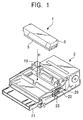
Fig. 1 is a perspective view of an inkjet head of an
embodiment of the present invention and a printer body, to
which the inkjet head is mounted, of a form used in the
present invention.
Fig. 2 is an enlarged transverse sectional view of the
inkjet head shown in Fig. 1.
Fig. 3 is a side view of specific examples of a head
cap, a cleaning roller, and an ink receiving section shown
in Fig. 2.
Fig. 4 is a plan view of the specific examples of the
head cap, the cleaning roller, and the ink receiving section.
Fig. 5 is a sectional view taken along line V-V of Fig.
4.
Fig. 6 illustrates means for detecting a timing of a
preliminary discharge operation from each ink discharge hole
carried out when the head cap moves relative to the print
head.
Figs. 7A and 7B schematically illustrate another form
of the cleaning roller.
Fig. 8 is a graph showing changes in an ink liquid
penetration distance with respect to an ink absorbing member
with time.
Fig. 9 schematically illustrates still another form of
the cleaning roller.
Fig. 10 schematically illustrates another form of the
ink receiving section of the head cap.
Fig. 11 schematically illustrates still another form of
the ink receiving section of the head cap.
Figs. 12A to 12F illustrate a cleaning operation using
the cleaning roller and the head cap of the inkjet head.
Fig. 13 is a perspective view of an inkjet printer of
an embodiment of the present invention in which the inkjet
head is mounted.
Fig. 14 is a perspective view similarly showing the
inkjet printer of the embodiment of the present invention in
which the head cap is removed.
Fig. 15 illustrates a specific mechanism in which the
inkjet head shown in Fig. 1 is accommodated in a
predetermined location of the printer body as a result of
insertion thereof in the direction of arrow H, and an
operation thereof.
Fig. 16 illustrates the specific mechanism in which the
inkjet head is secured to the predetermined location of the
printer body by a head mounting-and-dismounting mechanism
and in which the head cap is made movable, and an operation
thereof.
Fig. 17 illustrates the specific mechanism in which the
head cap mounted to the bottom surface of an ink cartridge
is being removed as a result of movement thereof in the
direction of arrow A, and an operation thereof.
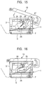
Fig. 18 illustrates the specific mechanism in which the
head cap successively moves in the direction of arrow A
along a movement path P, and an operation thereof.
Fig. 19 illustrates the specific mechanism in which the
head cap is at a withdrawal position as a result of
maximally moving in the direction of arrow A along the
movement path P, and an operation thereof.
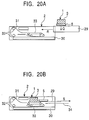
Figs. 20A and 20B schematically illustrate another type
of inkjet printer having the inkjet head mounted to the
printer body through a tray.
DESCRIPTION OF THE PREFERRED EMBODIMENTS
Hereunder, a detailed description of embodiments of the
present invention will be given with reference to the
attached drawings.
Fig. 1 is a perspective view of an inkjet head 1 of an
embodiment of the present invention and a printer body 2, to
which the inkjet head 1 is mounted, of a form used in the
present invention. In Fig. 1, the inkjet head 1 is
separately formed, and is of a type that is directly mounted
to the printer body 2. The inkjet head 1 is accommodated in
the direction of arrow H, and is set so as to be fixed to
the printer body 2 in order to form an inkjet printer.
The inkjet head 1 forms liquid ink into very fine
particles by, for example, electrothermal conversion or
electromechanical conversion, and discharges the very fine
particles in order to blow ink dots onto a recording sheet.
As shown in Figs. 1 and 2, the inkjet head 1 comprises an
ink cartridge 3, a print head 4, and a head cap 5.
The ink cartridge 3 holds ink of one color or of a
plurality of colors therein. Its housing is extended so as
to be elongated in the widthwise direction of the printer
body 2 shown in Fig. 1, that is, over the entire width of a
recording sheet in the widthwise direction thereof.
Although not shown, four divided ink chambers are formed
inside the housing and are filled with ink of corresponding
four colors, yellow Y, magenta M, cyan C, and black K. The
ink cartridge 3 is formed of, for example, a hard resin.
As shown in Fig. 2 (which is an enlarged transverse
sectional view of the inkjet head 1 shown in Fig. 1), the
print head 4 is provided at the bottom surface portion of
the ink cartridge 3. The print head 4 forms the ink
supplied from the ink cartridge 3 into very fine particles,
and discharges the very fine particles. The print head 4
includes ink discharge surfaces 6 having very small ink-discharge
holes provided in correspondence with the entire
width of a recording sheet along the longitudinal direction
of the ink cartridge 3. The ink discharge surfaces 6 extend
in the longitudinal direction of the ink cartridge 3, and
are provided in correspondence with the four colors of ink,
yellow Y, magenta M, cyan C, and black K, respectively.
Although not shown, the portions of the ink discharge
surfaces 6 that include the ink-discharge holes of the
corresponding colors of ink, Y, M, C, and K, and the
portions thereof that include protrusions where head
electrodes are covered with resin on both sides of the
corresponding ink-discharge holes are formed so as to have
undulating planar shapes.
The head cap 5 is mounted to the bottom surface of the
ink cartridge 3. The head cap 5 covers the ink discharge
surfaces 6 of the print head 4 and protects them in order to
prevent drying and clogging of the ink-discharge holes. The
head cap 5 extends so as to be elongated to the same length
as the housing of the ink cartridge 3, has the shape of a
box that is shallow and that has an open top side, and moves
relative to and is removably mounted to the print head 4.
The head cap 5 moves, as indicated by arrows A and B, in a
direction orthogonal to the longitudinal direction of the
ink discharge surfaces 6 of the print head 4. When the head
cap 5 has moved in the direction of arrow A, it is removed
from the ink cartridge 3, whereas, when the head cap 5 has
moved back in the direction of arrow B, it is placed on the
ink cartridge 3 again. The head cap 5 is formed of, for
example, a hard resin.
A cleaning roller 7 is provided at the inner side of
the head cap 5. The cleaning roller 7 is a cleaning member
for cleaning the ink discharge surfaces 6 of the print head
4, and is mounted at one side portion inside the head cap 5
in the longitudinal direction of the head cap 5. Therefore,
the cleaning roller 7 is provided parallel to the
longitudinal direction of the ink discharge surfaces 6 of
the print head 4. The cleaning roller 7 moves in the
direction of arrow A along with the head cap 5 in order to
clean the ink discharge surfaces 6 of the print head 4.
An ink receiving section 8 is similarly provided at the
inner side of the head cap 5. The ink receiving section 8
receives preliminarily discharged ink from the ink-discharge
holes of the print head 4, so that part of or the whole
bottom surface of the shallow-box-shaped head cap 5 receives
the preliminarily discharged ink.
Next, specific examples of the head cap 5, the cleaning
roller 7, and the ink receiving section 8 will be described
with reference to Figs. 3 to 5. In Fig. 4, the head cap 5
is formed into an elongated shape in accordance with the
width and length of the ink cartridge 3 shown in Fig. 1. As
shown in Fig. 3, the head cap 5 is formed with a bottom
surface (lower portion) and into the shape of a shallow box
in which a side of upstanding portions of side walls along
the entire periphery is open. As mentioned above, the head
cap 5 moves, as indicated by the arrows A and B, in a
direction orthogonal to the longitudinal direction of the
ink discharge surfaces 6 of the print head 4. As shown in
Fig. 3, as positioning means used when the head cap 5 is
placed onto the ink cartridge 3 again after the head cap 5
has moved back in the direction of arrow B, a positioning
pawl 12 is provided at the top end portion of a side wall of
the head cap 5 opposite to the cleaning roller 7. The
positioning pawl 12 positions the head cap 5 as a result of
being stopped by a side edge of the lower portion of the ink
cartridge 3.
The cleaning roller 7, which is formed into a circular
cylindrical shape and which comes into contact with the ink
discharge surfaces 6 of the print head 4 over the entire
length of the ink discharge surfaces 6, is removably held
near one of the side walls of the head cap 5 in the
longitudinal direction thereof at the print head 4 side of
the head cap 5. More specifically, as shown in Fig. 4,
protruding pins 9 are provided at both end portions of the
cleaning roller 7, and, as shown in Fig. 3, are held by
substantially U-shaped upstanding holding members 10. Pin-receiving
sections at the top portions of the holding
members 10 can be resiliently widened and narrowed. By
pushing the pins 9 against the pin-receiving sections from
thereabove, the pin-receiving sections are widened and
receive the pins 9, and, thereafter, are narrowed and hold
the pins 9. In contrast, by raising the pins 9 upward, the
pin-receiving sections are widened, so as to allow removal
of the pins 9.
As shown in Figs. 4 and 5, the circular cylindrical
shape of the cleaning roller 7 is what is called a crown
shape where the central portion in the longitudinal
direction thereof is moderately thick. The cleaning roller
7 has this shape to prevent the cleaning roller 7 from
moving out of contact with the ink discharge surfaces 6 when
the central portion of the cleaning roller 7 in the
longitudinal direction thereof flexes downward. The portion
of the cleaning roller 7 that comes into contact with the
ink discharge surfaces 6 is resilient and is formed of a
material that absorbs ink. More specifically, the core
material of the cleaning roller 7 is formed of, for example,
a metal or a hard resin, while the peripheral portion
thereof situated outwardly of the core material is formed of
a resilient material and a porous material having an ink
absorption property.
As shown in Fig. 3, a floating spring 11 is interposed
at the portion where the cleaning roller 7 is held by the
head cap 5. The floating spring 11 is means for biasing the
cleaning roller 7 towards the ink discharge surfaces 6 of
the print head 4; is, for example, a plate spring that is
substantially U-shaped in side view; and is inserted below
the pins 9 near the holding members 10. By causing the
biasing force of the floating spring 11 to act on the pins 9
at both end portions of the cleaning roller 7, the cleaning
roller 7 presses against the ink discharge surfaces 6 of the
print head 4 with a substantially uniform force.
By this, as shown in Fig. 2, with the head cap 5 being
placed on the bottom surface of the ink cartridge 3, the
cleaning roller 7 is such as to come into contact with the
entire length of the ink discharge surfaces 6 of the print
head 4 due to the biasing force of the floating spring 11
and the resilient force and the crown shape of the cleaning
roller 7. The floating spring 11 is not limited to a
substantially U-shaped plate spring, so that it may be a
coil spring.
The cleaning roller 7 is such as to be driven and
rotated as a result of coming into contact with the ink
discharge surfaces 6 of the print head 4. Therefore, as
shown in Fig. 2, when the head cap 5 moves in the direction
of arrow A, the cleaning roller 7 rotates while it comes
into close contact with the entire length of the ink
discharge surfaces 6 of the print head 4 with a proper
pressure in order to, by this rotational movement, clean off
the ink that has adhered to the ink discharge surfaces 6.
In this case, it is possible to clean off the ink without
injuring protective layers where head electrodes provided at
the ink discharge surfaces 6 are covered with resin.
The cleaning roller 7 may be secured so as not to
rotate while it is in contact with any one of the ink
discharge surfaces 6 of the print head 4. For example, in
Fig. 3, by providing two pins 9 at both end portions of the
cleaning roller 7 in the vertical direction, and by
inserting the two pins 9 at both end portions into a
substantially U-shaped groove of the holding members 10, the
cleaning roller 7 is prevented from rotating. In this case,
the cleaning roller 7 moves while it rubs against the ink
discharge surfaces 6. Therefore, it is possible to clean
off solidified ink stuck on the ink discharge surfaces 6,
not to mention liquid ink stuck on the ink discharge
surfaces 6.
The cleaning roller 7 may be such as to rotate while it
rubs against the ink discharge surfaces 6 of the print head
4 by limiting the rotation of the cleaning roller 7 by a
braking mechanism. For example, in Fig. 3, the braking
mechanism is a mechanism in which a proper resilient member
is interposed at the portion where the pins 9 provided at
both end portions of the cleaning roller 7 are held by the
holding members 10, and in which the pins 9 are press-fitted
to a hole formed in the resilient member, or both end
surfaces of the cleaning roller 7 are press-contacted to a
side surface of the resilient member. The braking mechanism
produces a proper braking force when the cleaning roller 7
rotates. In this case, since the cleaning roller 7 rotates
slightly while it rubs against the ink discharge surfaces 6,
it can clean off solidified ink stuck on the ink discharge
surfaces 6, not to mention liquid ink stuck on the ink
discharge surfaces 6, without injuring the ink discharge
surfaces 6.
As shown in Figs. 3 to 5, an ink-absorbing member 13 is
laid on a receiving surface, or bottom surface, of the ink
receiving section 8 at the inner side of the head cap 5.
The ink-absorbing member 13 is means for preventing ink
preliminarily discharged from the print head 4 from
spattering back; is formed of a porous, high molecular
material, such as sponge, polyurethane, or polyurethane foam,
and; as shown in Fig. 4, is laid over substantially the
entire receiving surface of the ink-receiving section 8.
However, as shown in Fig. 5, the ink-absorbing member 13 is
not laid below the large-diameter central portion of the
crown-shaped cleaning roller 7 in order to provide clearance
therebelow.
When the ink-absorbing member 13 is laid as described
above, the preliminarily discharged ink from the print head
4 shown in Fig. 2 is prevented from spattering back, and the
ink can be absorbed thereby so that the ink does not collect
at the ink-receiving section 8. Therefore, the problem that
the preliminarily discharged ink re-adheres onto the ink
discharge surfaces 6 as a result of being spattered back at
the ink-receiving section 8 is prevented from occurring.
After using the ink-absorbing member 13 for a proper period
of time, the ink-absorbing member 13 that has absorbed the
preliminarily discharged ink is removed from the ink-receiving
section 8 and discarded in order to lay another
ink-absorbing member 13, thereby making it possible to
easily clean off the preliminarily discharged ink.
Although, in the form shown in Figs. 3 to 5, the ink-receiving
section 8 is described as being provided along the
entire bottom surface of the head cap 5, the present
invention is not limited thereto, so that the ink-receiving
section 8 may be provided along part of the bottom surface
of the head cap 5. For example, in Fig. 2, the cleaning
roller 7 may be slightly moved towards the center portion,
and a partition plate may be provided between a cleaning-roller-7-side
side wall of the head cap 5 and the cleaning
roller 7 in order to form a chamber surrounded by the
partition plate and the side wall as the ink-receiving
section 8. In this case, it is possible to limit the
location that receives the preliminarily discharged ink from
the ink-discharge holes of the print head 4 to a particular
location of the head cap 5.
Next, the preliminary discharge of ink from the ink-discharge
holes of the print head 4 will be described. The
preliminary discharge of ink is carried out to, for example,
suck and discharge ink inside the ink-discharge holes prior
to printing or photographic printing for the purpose of
preventing the problem that normal ink discharge becomes
difficult to achieve due to increased viscosity or
solidification of ink caused by evaporation drying of the
ink inside the ink-discharge holes as described above. The
preliminary discharge of ink from the ink-discharge holes
towards the ink-receiving section 8 of the head cap 5 before
or after cleaning the ink discharge surfaces 6 by the
cleaning roller 7. For example, discharging of ink drops
from the ink-discharge holes of the print head 4 at a
frequency of the order of 10 kHz is repeated a few times in
order to carry out the preliminary discharge of ink.
In Fig. 2, when the preliminary discharge of ink is
carried out before cleaning the Y, M, C, and K colored ink
discharge surfaces 6, it is not necessary to particularly
control a timing of the preliminary discharge of the ink
from each of the ink-discharge holes, so that the
preliminary discharge may be carried out before or after the
head cap 5 starts moving, or from each of the colored ink
discharge holes simultaneously. In these cases, the
preliminary discharge of ink can be easily controlled.
However, when, in order to avoid mixing of colors resulting
from cleaning the colored ink discharge surfaces 6 using one
cleaning roller 7, the preliminary discharge of ink is
carried out after cleaning the colored ink discharge
surfaces 6, it is necessary to control the timing of the
preliminary discharge of ink.
Therefore, as shown in Fig. 6, means for detecting a
timing of preliminarily discharging ink from the ink-discharge
holes of the print head 4 when the head cap 5
moves relative to the print head 4 is provided at the head
cap 5. In Fig. 6, the cap head 5 moves in a direction
opposite to that in Fig. 2.
In Fig. 6, the preliminary discharge timing detecting
means comprises a position detection sheet 14 provided at
the bottom surface side of the head cap 5 and a
photoelectric switch 15 opposing the position detection
sheet 14 and provided inside the printer body 2 shown in Fig.
1. The position detection sheet 14 is provided for
examining locations corresponding to the colored ink
discharge surfaces 6 of the print head 4 when the head cap 5
moves in the direction of arrow A, and has, for example, a
light and dark pattern formed in correspondence with an
arrangement pitch of the Y, M, C, and K ink discharge
surfaces 6. The arrangement of the portions of the pattern
is opposite to the order of arrangement of each of the
colors, Y, M, C, and K for each of the ink discharge
surfaces 6. In the initial stage of movement of the head
cap 5, the arrangement of the portions of the pattern on the
position detection sheet 14 is displaced towards the back
when viewed in the direction of arrow A.
The photoelectric switch 15 is provided for detecting
the light and dark pattern on the position detection sheet
14 that moves along with the head cap 5, and is formed by
integrally combining a light-emitting section 16, such as a
light-emitting diode (LED), and a light receiving detecting
section 17, which is a photodiode. The light and dark
pattern on the position detection sheet 14 changes its
reflectivity with respect to the wavelength of light emitted
from the light emitting section 16, and the light receiving
detecting section 17 is sensitive to the wavelength of the
reflected light.
By such a structure, when the head cap 5 moves in the
direction of arrow A, so that the position detection sheet
14 at the bottom surface of the head cap 5 passes in front
of the photoelectric switch 15, it is possible to detect the
light and dark pattern on the position detection sheet 14 in
order to examine the locations corresponding to the
locations of the Y, M, C, and K ink discharge surfaces 6.
By this, the position of the cleaning roller 7 that moves
with the head cap 5 is known, and, immediately after
cleaning each of the colored ink discharge surfaces 6 by the
cleaning roller 7, the timing is controlled so that the
preliminary discharge of ink from each of the ink-discharge
holes is successively carried out. At this time, the ink
that has been preliminary discharged is reliably held inside
the ink-receiving section 8.
Figs. 7A and 7B schematically illustrate another form
of the cleaning roller 7. In this form, the cleaning roller
7 is such as to rotate forward or backward by a rotation
driving mechanism. More specifically, in Fig. 2, a rotary
shaft of a motor (not shown) provided inside the printer
body 2 is connected to the pins 9, provided at the cleaning
roller 7, through a gear mechanism having a proper reduction
ratio, so that the cleaning roller 7 is actively
rotationally driven.
As shown in Fig. 7A, the cleaning roller 7 is rotated
by the motor in the same direction as the direction of
movement of arrow A of the head cap 5 shown in Fig. 6 and
with a rotating speed that is set so that an outer
peripheral speed v2 of the cleaning roller 7 is greater than
a movement speed v1 of the head cap 5. In this case, the ink
discharge surfaces 6 are reliably cleaned by rubbing that is
based on the difference in speeds between the ink discharge
surfaces 6 of the print head 4 and the outer peripheral
surface of the cleaning roller 7. Even when the motor is
rotated with a rotating speed that is set so that the
movement speed v1 of the head cap 5 is greater than the outer
peripheral speed v2 of the cleaning roller 7, rubbing occurs
between the ink discharge surfaces 6 and the outer
peripheral surface of the cleaning roller 7 as mentioned
above, so that the ink discharge surfaces 6 are reliably
cleaned.
As shown in Fig. 7B, the cleaning roller 7 may be made
to rotate in a direction opposite to the direction of
movement of arrow A of the head cap 5 shown in Fig. 6. In
this case, rubbing occurs due to a difference between the
directions of movement of the ink discharge surfaces 6 of
the print head 4 and the outer peripheral surface of the
cleaning roller 7, so that the ink discharge surfaces 6 are
reliably cleaned.
In the form shown in Fig. 7, the ink discharge surfaces
6 of the print head 4 are cleaned by outer peripheral
surface portions that are successively provided by the
active rotation of the cleaning roller 7. When this is seen
in terms of changes in ink liquid penetration distance with
respect to the ink-absorbing member with time when, for
example, the circular cylindrical ink-absorbing member has
been immersed in the ink liquid, it is known that, as shown
in Fig. 8, the rate of increase of a penetration distance 1
is initially large, but gradually decreases with the passage
of time t.
For example, when the radius of the circular
cylindrical ink-absorbing member is r, the surface tension
of a liquid (ink) is γ, the viscosity of the liquid is η,
the angle of contact between the liquid and the ink-absorbing
member is , and the difference in external
pressures exerted on both ends of the circular cylindrical
ink-absorbing member is Δp, the penetration distance l is
expressed by the following general formula:
l2 = (r2 / 4η) {(2γ · cos / r) + Δp} t
In other words, when, as in the form shown in Figs. 7A
and 7B, rubbing is caused to positively occur between the
ink discharge surfaces 6 and the outer peripheral surface of
the cleaning roller 7 by a difference in speeds and
directions of movement, a cleaning effect in which the
possibility of incomplete wiping of the ink discharge
surfaces 6 is small can be expected.
Fig. 9 schematically illustrates still another form of
the cleaning roller 7. In this form, the cleaning roller 7
is formed so that the length of the cross-sectional
circumference of the cleaning roller 7 is equal to the
movement distance covered by the cleaning roller 7 when it
is driven and rotates by coming into contact with the ink
discharge surfaces 6 of the print head 4. More specifically,
in Fig. 9, when a length equal to the total lengths of the
ink discharge surfaces 6 in the direction in which a
recording sheet is fed is L, and a diameter of the cleaning
roller 7 is D, the length of the cross-sectional
circumference of the cleaning roller 7 is πD. Therefore, in
this case, the formula L = πD is established, so that D = L
/ π. In other words, the diameter D of the cleaning roller
7 is determined so that D = L / π.
By such a structure, as shown in Fig. 9, the Y, M, C,
and K colored ink discharge surfaces 6 are always cleaned by
the same outer peripheral surface portions as a result of
one rotation of the cleaning roller 7 because the outer
peripheral surface portions of the cleaning roller 7 roll on
the Y, M, C, and K colored ink discharge surfaces 6 as a
result of the cleaning roller 7 being driven and rotating in
the direction of arrow G while moving in the direction of
arrow F. Therefore, a particular outer peripheral surface
portion of the cleaning roller 7 always comes into contact
with the same ink discharge surface 6, so that mixing of
colors in that ink discharge surface 6 does not occur.
Therefore, there is no possibility of the quality of
printing and photographic printing by the inkjet head
getting reduced.
Fig. 10 schematically illustrates another form of the
ink-receiving section 8 provided at the head cap 5. In this
form, the receiving surface of the ink-receiving section 8
is formed into a rough surface. The rough surface is means
for preventing preliminarily discharged ink from the print
head 4 from being spattered back; is, for example, jagged,
bumpy, or wavy; and causes the preliminarily discharged ink
to be scattered sideways rather than being spattered back
upward. By the rough surface, the preliminarily discharged
ink is prevented from re-adhering to the ink discharge
surfaces 6 of the print head 4.
Fig. 11 schematically illustrates still another form of
the ink-receiving section 8 provided at the head cap 5. In
this form, the receiving surface of the ink-receiving
section 8 is formed into an inclined surface that inclines
towards one side in the longitudinal direction of the ink
discharge surfaces 6 of the print head 4. The inclined
surface is means for preventing ink that has been
preliminarily discharged from the print head 4 from being
spattered back. The preliminarily discharged ink flows
along the inclined surface and collects at an end at one
side of the inclined surface, so that the receiving surface
of the ink-receiving section 8 is maintained in a clean
state. By this, any ink remaining on the receiving surface
after a previous preliminary discharge operation is
spattered back by the currently preliminarily discharged ink
in order to eliminate the possibility of the residual ink
re-adhering to the ink discharge surfaces 6 of the print
head 4. As shown in Fig. 10, the receiving surface of the
inclined ink-receiving section 8 may be formed into a rough
surface.
Next, a description of the cleaning operation by the
cleaning roller 7 and the head cap 5 of the inkjet head 1
having a structure such as those described above will be
given with reference to Fig. 12. Here, in the inkjet head 1
shown in Fig. 6, the head cap 5 moves in the direction of
arrow A in order to clean the ink discharge surfaces 6 of
the print head 4, after which a preliminary discharge
operation of ink is carried out. Fig. 12A shows an initial
state in which the head cap 5 is placed on the ink cartridge
3. From the state shown in Fig. 1, the inkjet head 1 is
accommodated and set in the printer body 2.
Next, with the inkjet head 1 being set in the printer
body 2, as shown in Fig. 12B, the head cap 5 is moved in the
direction of arrow A relative to the ink cartridge 3 by a
head cap removal signal. This causes the cleaning roller 7
to move in the direction of arrow A along with the head cap
5 with respect to the ink cartridge 3, so that, with the
cleaning roller 7 being pushed against and brought into
contact with the ink discharge surfaces 6 of the print head
4, the ink discharge surfaces 6 are cleaned. At this time,
the cleaning roller 7 is driven and rotates while it is in
contact with any one the ink discharge surfaces 6, the
cleaning roller 7 is fixed, the rotation of the cleaning
roller 7 is limited by a braking mechanism, or the cleaning
roller 7 moves while being rotated in the forward or back
direction by a motor.
In this state, in Fig. 6, of the ink discharge surfaces
6 of the print head 4, for example, the yellow Y ink
discharge surfaces 6 is cleaned. Here, the yellow Y portion
of the position detection sheet 14, provided at the bottom
surface of the head cap 5, moves to a detection location of
the photoelectric switch 15 in order to detect that the
cleaning of the yellow Y ink discharge surface 6 is
completed. This causes a preliminary discharge start signal
to be sent to the ink discharge hole of the yellow Y ink
discharge surface.
Next, as shown in Fig. 12C, preliminary discharge ink
18 is ejected from the ink-discharge hole of the yellow Y
ink discharge surface 6. Then, a preliminary discharge
completion signal is sent to the ink-discharge hole of the
yellow Y ink discharge surface 6 in order to stop the
ejection of the preliminary discharge ink 18. Thereafter,
similarly, in Fig. 6, each time the cleaning roller 7
successively finishes cleaning each of the M, C, and K ink
discharge surfaces 6, the photoelectric switch 15 detects
completion of the cleaning of each of the ink discharge
surfaces 6 in order to send a preliminary discharge start
signal and a preliminary discharge completion signal to each
of the ink-discharge holes. By this, a timing of the
preliminary discharge operation from each of the ink-discharge
holes is controlled, so that the ink preliminary
discharge operations are successively carried out.
In this way, when the cleaning of and the preliminary
discharge operation from each of the colored ink discharge
surfaces 6 end, as shown in Fig. 12D, the head cap 5 moves
maximally in the direction of arrow A, moves slightly upward,
and settles in a withdrawal position. In this state,
printing or photographic printing is performed on a
recording sheet.
Next, when the printing or photographic printing on a
required number of pages is completed, a head cap placing
signal is transmitted, so that, as shown in Fig. 12E, the
head cap 5 moves in the direction of arrow B relative to the
ink cartridge 3 from the aforementioned withdrawal position.
This causes the cleaning roller 7 to move in the direction
of arrow B along with the head cap 5 with respect to the ink
cartridge 3, so that, with the cleaning roller 7 being
pushed against and coming into contact with the ink
discharge surfaces 6 of the print head 4, the cleaning
roller 7 moves back while cleaning the ink discharge
surfaces 6.
Thereafter, as shown in Fig. 12F, the head cap 5 moves
maximally in the direction of arrow B with respect to the
ink cartridge 3, and covers the ink cartridge 3, thereby
returning to its initial state. Then, the printer waits for
the next printing or photographic printing command.
The above-described operations have been described as
being carried out when the ink preliminary discharge
operations are carried out after cleaning the ink discharge
surfaces 6 of the print head 4. However, if there is no
possibility of a mixing of colors by the cleaning roller 7
that comes into contact with the ink discharge surfaces 6,
the preliminary discharge of ink may be carried out before
cleaning the ink discharge surfaces 6 by the cleaning roller
7. In this case, it is not necessary to control the timing
of the preliminary discharge operation from each of the Y, M,
C, and K colored ink discharge holes, or to provide the
position detection sheet 14 and the photoelectric switch 15
shown in Fig. 6.
Next, a description of an inkjet printer as a related
invention of the inkjet head will be described with
reference to Fig. 1 and Figs. 13 to 19. The inkjet printer
performs printing by forming ink from the inkjet head into
very fine particles and discharging them, and blowing ink
dots onto a recording sheet. As shown in Fig. 1, it
comprises the inkjet head 1, the printer body 2, a head
mounting-and-dismounting mechanism 19, and a head cap
placing-and-removing mechanism 20. The inkjet printer is
shown as a type in which the inkjet head 1 is directly
mounted to the printer body 2.
The inkjet head 1 forms liquid ink into very fine
particles by, for example, electrothermal conversion or
electromechanical conversion, and discharges the very fine
particles in order to blow ink dots onto a recording sheet.
Therefore, the inkjet head 1 has the same structure as that
described in Figs. 1 to 12.
The printer body 2 is provided to function as an inkjet
printer by mounting the inkjet head 1 to a predetermined
location thereof, and comprises a recording-sheet tray, a
recording-sheet transporting system, an operational driving
system, and a control circuit portion for controlling the
entire printer body 2. In Fig. 1, reference numeral 21
denotes a discharged-sheet receiver to which sheets are
discharged after printing.
The head mounting-and-dismounting mechanism 19 is
provided to mount the inkjet head 1 to and dismount it from
a predetermined location of the printer body 2, and
comprises, for example, an elongated bar member which holds
down the top surface portion of the inkjet head 1 by
insertion of the inkjet head 1 into the predetermined
location, that is, a recess in the center portion of the
printer body 2. In other words, the head mounting-and-dismounting
mechanism 19 extends in the direction of the
entire width of the printer body 2, and is such as to be,
for example, raised and lowered in the vertical and the
horizontal directions, respectively. With the bar member
being raised in the vertical direction as shown in Fig. 1,
the inkjet head 1 is accommodated and mounted in the
direction of arrow H, and, with the bar member being lowered
in the horizontal direction as shown in Fig. 13, the inkjet
head 1 is secured to the predetermined location.
With the inkjet head 1 being secured to the
predetermined location of the printer body 2, the head cap
placing-and-removing mechanism 20 causes the head cap 5 to
move relative to the print head 4 (see Fig. 2) in order to
uncover the ink discharge surfaces 6 (see Fig. 2), and
causes the head cap 5 to be placed on the print head 4 after
printing. The head cap placing-and-removing mechanism 20 is
formed by, for example, engaging a pinion 23 and a rack 22,
both of which are provided at a side surface of the printer
body 2. A pin-like protrusion is provided at a side surface
at the inner side of the rack 22, and is fitted to a recess
formed in a corresponding portion of the outer-side surface
of the head cap 5.
As shown in Fig. 13, with the inkjet head 1 being
secured to the predetermined location of the printer body 2
by the head mounting-and-dismounting mechanism 19, when the
pinion 23 is rotated in a predetermined direction by a motor
(not shown), as shown in Fig. 14, the rack 22 moves in the
direction of arrow A, causing the head cap 5 shown in Fig. 1
to move in the direction of arrow A, to be removed, and to
settle in the withdrawal position.
The head cap placing-and-removing mechanism 20 is not
limited to an engagement of the rack 22 and the pinion 23.
For example, there may be used another head cap placing-and-removing
mechanism in which a rubber roller pushes against
both side surfaces of the head cap 5, a motor is connected
to a rotary shaft of the rubber roller, and the motor is
rotated in order to move the head cap 5 in the direction of
arrow A by friction of the rubber roller and to remove it.
Next, with reference to Figs. 15 to 19, there will be
described a specific example of a mechanism used to uncover
the ink discharge surfaces 6 (see Fig. 2) by moving the head
cap 5 relative to the print head 4 (see Fig. 2) after
securing the inkjet head 1 to the predetermined location of
the printer body 2 shown in Fig. 1.
Fig. 15 shows a state in which the inkjet head 1 shown
in Fig. 1 is accommodated in the predetermined location of
the printer body 2 by insertion thereof in the direction of
arrow H. In this state, the bottom ends of cap lock hooks
24 provided at both side end portions inside the inkjet head
1 engage corresponding stopper portions 26 at both side
portions of the head cap 5 by a resilient force of a helical
spring 25. By this, the head cap 5 is integrally mounted to
the ink cartridge 3.
In this state, in Fig. 15, the head mounting-and-dismounting
mechanism 19 is pushed down in the direction of
arrow J and is secured. This causes a cap unlocking portion
27 provided at the bottom side portion of the head mounting-and-dismounting
mechanism 19 to push down and rotate top end
portions 28 of the cap lock hooks 24. As shown in Fig. 16,
this causes the bottom end portions of the cap lock hooks 24
to be lifted in order to disengage them from the
corresponding stopper portions 26 at both side portions of
the head cap 5. By this, as shown in Fig. 13, the inkjet
head 1 is secured to the predetermined location of the
printer body 2 by the head mounting-and-dismounting
mechanism 19, and the head cap 5 becomes movable.
Next, the head cap placing-and-removing mechanism 20,
shown in Fig 13, is operated in order to rotate the pinion
23 by a motor (not shown) and to move the rack 22 in the
direction of arrow A. As shown in Fig. 17, this causes the
head cap 5, mounted to the bottom surface of the ink
cartridge 3, to move, along with the rack 22, in the
direction of arrow A and to be subjected to a removing
operation. Then, as shown in Fig. 2, the cleaning roller 7
biased by the floating spring 11 starts cleaning the ink
discharge surfaces 6 of the print head 4 provided at the
bottom surface of the ink cartridge 3. In Fig. 17,
reference character P denotes a path of movement of the head
cap 5.
Thereafter, as shown in Fig. 18, the head cap 5 moves
successively in the direction of arrow A along the movement
path P. At this time, by the cleaning roller 7 mounted to
the head cap 5, each of the Y, M, C, and K colored ink
discharge surfaces 6, shown in Fig. 2, are successively
cleaned, and preliminary discharge operations of ink are
carried out before or after the cleaning operation.
When the cleaning of and the preliminary discharge from
each of the colored ink discharge surfaces 6 are completed,
as shown in Fig. 19, the head cap 5 moves maximally in the
direction of arrow A along the movement path P and is moved
slightly upward, so that it settles in the withdrawal
position, as shown in Fig. 14. In this state, printing or
photographic printing is carried out on a recording sheet.
At this time, since, as shown in Fig. 19, the head cap 5 is
moved slightly upward, the space required to accommodate it
can be made small. In Fig. 19, although the recording sheet
passes below the printer head 4 provided at the bottom
surface of the ink cartridge 3, the passage of the recording
sheet may be guided by the bottom surface of the head cap 5.
In this case, a rib for guiding the recording sheet may be
provided at the bottom surface of the head cap 5. A water-repellency
process may be carried out so that ink does not
stick onto the recording sheet that has been subjected to
printing.
In this state, when the printing or photographic
printing of a required number of pages is completed, the
head cap 5 moves in the direction of arrow B from the
withdrawal position shown in Fig. 19 by the above-described
operations performed in reverse order, and, as shown in Fig.
16, the head cap 5 returns to its initial state by returning
to the bottom surface of the ink cartridge 3.
Then, in Fig. 15, when the head mounting-and-dismounting
mechanism 19 opens in a direction opposite to
the direction of arrow J, the cap lock hooks 24 engage the
stopper portions 26 at both side portions of the head cap 5
by the resilient force of the helical spring 25, so that the
head cap 5 is integrally mounted to the ink cartridge 3. In
this state, as shown in Fig. 1, the inkjet head 1 can be
removed from the printer body 2.
With the head cap 5 being at the withdrawal position
shown in Fig. 19, when a power supply of the printer is
turned off for some reason, the head cap 5 remains at the
aforementioned withdrawal position. In this state, as shown
in Fig. 15, when the head mounting-and-dismounting mechanism
19 opens in a direction opposite to the direction of arrow J,
the ink cartridge 3 alone is removed with the head cap 5
remaining at the withdrawal position. To prevent this, an
interlock mechanism may be provided to cause the head cap 5
at the withdrawal position to automatically return to its
initial position shown in Fig. 15 when the power supply of
the printer is turned off for some reason, or to prevent the
head mounting-and-dismounting mechanism 19 from opening in a
direction opposite to the direction of arrow J when the head
cap 5 has not returned to its initial position shown in Fig.
15.
The inkjet printer illustrated in Figs. 13 to 19 is of
the type in which the inkjet head 1 is directly mounted to
the printer body 2. However, the present invention is not
limited thereto, so that an inkjet printer of the type in
which the inkjet head 1 is mounted to the printer body 2
through a tray may similarly be used. Hereunder, a general
description of another type of inkjet printer will be given
with reference to Fig. 20.
As shown in Fig. 20A, the inkjet head 1 that includes
the head cap 5 integrally mounted to the ink cartridge 3 is
mounted in the direction of arrow Q to a predetermined
location at the inner side of a tray 29 which is provided so
that it can advance and retreat with respect to the printer
body 2. Thereafter, the tray 29 is moved in the direction
of arrow R and is set inside the printer body 2. At this
time, as shown in Fig. 20B, while the tray 29 is moving in
the direction of arrow R, the head cap 5 is retained and
stopped by proper retaining means provided inside the
printer body 2. The tray 29 is provided for setting the
inkjet head 1 inside the printer body 2 and for replacing it.
Thereafter, by moving the tray 29 in the direction of
arrow R, the ink cartridge 3 moves in the direction of arrow
R relative to the head cap 5, so that the head cap 5 is
subjected to a removing operation. At the same time, by
performing the same operations as those illustrated in Fig.
12 while the head cap 5 is moving in the direction of arrow
R relative to the ink cartridge 3, the ink discharge
surfaces 6 of the print head 4 are cleaned and preliminary
discharge operations of ink are carried out. Thereafter,
printing or photographic printing is carried out on a
recording sheet. In Fig. 20, reference numeral 30 denotes a
recording sheet tray, reference numeral 31 denotes a
recording sheet, reference numeral 32 denotes a feed roller,
reference numeral 33 denotes a feed belt, reference numeral
34 denotes a sheet-discharge tray, and reference character S
denotes the direction in which the recording sheet is
discharged.
In this type of inkjet printer shown in Fig. 20, the
means for detecting a timing of a preliminary discharge
operation from each ink discharge hole of the print head 4
shown in Fig. 6 is provided at the side of the ink cartridge
3 that moves in the direction of arrow R. In other words,
in Fig. 6, the position detection sheet 14 may be provided
at the top surface side of the ink cartridge 3, and the
photoelectric switch 15 may be provided above the ink
cartridge 3 and inside the printer body 2 so as to oppose
the position detection sheet 14.