EP1236499B1 - SCR process and apparatus for the reduction of NOx emissions - Google Patents
SCR process and apparatus for the reduction of NOx emissions Download PDFInfo
- Publication number
- EP1236499B1 EP1236499B1 EP02003645A EP02003645A EP1236499B1 EP 1236499 B1 EP1236499 B1 EP 1236499B1 EP 02003645 A EP02003645 A EP 02003645A EP 02003645 A EP02003645 A EP 02003645A EP 1236499 B1 EP1236499 B1 EP 1236499B1
- Authority
- EP
- European Patent Office
- Prior art keywords
- reducing agent
- liquid reducing
- membrane
- liquid
- tank
- Prior art date
- Legal status (The legal status is an assumption and is not a legal conclusion. Google has not performed a legal analysis and makes no representation as to the accuracy of the status listed.)
- Expired - Lifetime
Links
- 238000000034 method Methods 0.000 title claims abstract description 24
- 230000009467 reduction Effects 0.000 title description 11
- 239000003638 chemical reducing agent Substances 0.000 claims abstract description 67
- MWUXSHHQAYIFBG-UHFFFAOYSA-N nitrogen oxide Inorganic materials O=[N] MWUXSHHQAYIFBG-UHFFFAOYSA-N 0.000 claims abstract description 60
- 239000007788 liquid Substances 0.000 claims abstract description 43
- 239000012528 membrane Substances 0.000 claims abstract description 40
- 239000007789 gas Substances 0.000 claims abstract description 36
- 239000012530 fluid Substances 0.000 claims abstract description 25
- 238000006073 displacement reaction Methods 0.000 claims abstract description 24
- XSQUKJJJFZCRTK-UHFFFAOYSA-N Urea Chemical compound NC(N)=O XSQUKJJJFZCRTK-UHFFFAOYSA-N 0.000 claims description 53
- 239000004202 carbamide Substances 0.000 claims description 53
- QGZKDVFQNNGYKY-UHFFFAOYSA-N Ammonia Chemical compound N QGZKDVFQNNGYKY-UHFFFAOYSA-N 0.000 claims description 30
- 229910021529 ammonia Inorganic materials 0.000 claims description 11
- 238000002156 mixing Methods 0.000 claims description 9
- 239000002283 diesel fuel Substances 0.000 claims description 5
- 230000033228 biological regulation Effects 0.000 claims description 4
- 238000001816 cooling Methods 0.000 claims description 2
- 239000000110 cooling liquid Substances 0.000 claims 1
- 239000003570 air Substances 0.000 description 24
- 239000000243 solution Substances 0.000 description 13
- 238000007710 freezing Methods 0.000 description 11
- 230000008014 freezing Effects 0.000 description 11
- 238000006722 reduction reaction Methods 0.000 description 10
- XLYOFNOQVPJJNP-UHFFFAOYSA-N water Substances O XLYOFNOQVPJJNP-UHFFFAOYSA-N 0.000 description 8
- 239000003054 catalyst Substances 0.000 description 7
- CURLTUGMZLYLDI-UHFFFAOYSA-N Carbon dioxide Chemical compound O=C=O CURLTUGMZLYLDI-UHFFFAOYSA-N 0.000 description 6
- IJGRMHOSHXDMSA-UHFFFAOYSA-N Atomic nitrogen Chemical compound N#N IJGRMHOSHXDMSA-UHFFFAOYSA-N 0.000 description 5
- 229910002092 carbon dioxide Inorganic materials 0.000 description 5
- 239000002826 coolant Substances 0.000 description 5
- 238000002425 crystallisation Methods 0.000 description 5
- 230000006378 damage Effects 0.000 description 5
- 239000007787 solid Substances 0.000 description 5
- 238000001321 HNCO Methods 0.000 description 4
- OWIKHYCFFJSOEH-UHFFFAOYSA-N Isocyanic acid Chemical compound N=C=O OWIKHYCFFJSOEH-UHFFFAOYSA-N 0.000 description 4
- 230000008025 crystallization Effects 0.000 description 4
- 229910000069 nitrogen hydride Inorganic materials 0.000 description 4
- 229920002943 EPDM rubber Polymers 0.000 description 3
- 238000006243 chemical reaction Methods 0.000 description 3
- 239000000463 material Substances 0.000 description 3
- 239000000203 mixture Substances 0.000 description 3
- 238000012546 transfer Methods 0.000 description 3
- MGWGWNFMUOTEHG-UHFFFAOYSA-N 4-(3,5-dimethylphenyl)-1,3-thiazol-2-amine Chemical compound CC1=CC(C)=CC(C=2N=C(N)SC=2)=C1 MGWGWNFMUOTEHG-UHFFFAOYSA-N 0.000 description 2
- VHUUQVKOLVNVRT-UHFFFAOYSA-N Ammonium hydroxide Chemical compound [NH4+].[OH-] VHUUQVKOLVNVRT-UHFFFAOYSA-N 0.000 description 2
- 229910000831 Steel Inorganic materials 0.000 description 2
- 238000010276 construction Methods 0.000 description 2
- 239000013078 crystal Substances 0.000 description 2
- 230000008021 deposition Effects 0.000 description 2
- 238000000151 deposition Methods 0.000 description 2
- 229920001821 foam rubber Polymers 0.000 description 2
- 238000010438 heat treatment Methods 0.000 description 2
- 239000010720 hydraulic oil Substances 0.000 description 2
- 230000007257 malfunction Effects 0.000 description 2
- 229910052757 nitrogen Inorganic materials 0.000 description 2
- JCXJVPUVTGWSNB-UHFFFAOYSA-N nitrogen dioxide Inorganic materials O=[N]=O JCXJVPUVTGWSNB-UHFFFAOYSA-N 0.000 description 2
- 239000010959 steel Substances 0.000 description 2
- 229910001369 Brass Inorganic materials 0.000 description 1
- ODUCDPQEXGNKDN-UHFFFAOYSA-N Nitrogen oxide(NO) Natural products O=N ODUCDPQEXGNKDN-UHFFFAOYSA-N 0.000 description 1
- 239000007864 aqueous solution Substances 0.000 description 1
- 230000009286 beneficial effect Effects 0.000 description 1
- 230000015572 biosynthetic process Effects 0.000 description 1
- 239000010951 brass Substances 0.000 description 1
- 239000001569 carbon dioxide Substances 0.000 description 1
- 238000010531 catalytic reduction reaction Methods 0.000 description 1
- 150000001875 compounds Chemical class 0.000 description 1
- 230000007797 corrosion Effects 0.000 description 1
- 238000005260 corrosion Methods 0.000 description 1
- 238000013461 design Methods 0.000 description 1
- 230000001066 destructive effect Effects 0.000 description 1
- 238000010586 diagram Methods 0.000 description 1
- 230000000694 effects Effects 0.000 description 1
- 229920001971 elastomer Polymers 0.000 description 1
- 230000005611 electricity Effects 0.000 description 1
- 238000005516 engineering process Methods 0.000 description 1
- 230000008020 evaporation Effects 0.000 description 1
- 238000001704 evaporation Methods 0.000 description 1
- 230000001747 exhibiting effect Effects 0.000 description 1
- 239000002803 fossil fuel Substances 0.000 description 1
- 230000030279 gene silencing Effects 0.000 description 1
- 231100001261 hazardous Toxicity 0.000 description 1
- 238000009413 insulation Methods 0.000 description 1
- ZFSLODLOARCGLH-UHFFFAOYSA-N isocyanuric acid Chemical compound OC1=NC(O)=NC(O)=N1 ZFSLODLOARCGLH-UHFFFAOYSA-N 0.000 description 1
- 231100000518 lethal Toxicity 0.000 description 1
- 230000001665 lethal effect Effects 0.000 description 1
- 238000012544 monitoring process Methods 0.000 description 1
- 231100000252 nontoxic Toxicity 0.000 description 1
- 230000003000 nontoxic effect Effects 0.000 description 1
- 238000001556 precipitation Methods 0.000 description 1
- 230000001681 protective effect Effects 0.000 description 1
- 238000000197 pyrolysis Methods 0.000 description 1
- 230000003134 recirculating effect Effects 0.000 description 1
- 230000001105 regulatory effect Effects 0.000 description 1
- 229920006395 saturated elastomer Polymers 0.000 description 1
- 238000000926 separation method Methods 0.000 description 1
- 231100000331 toxic Toxicity 0.000 description 1
- 230000002588 toxic effect Effects 0.000 description 1
- 238000013022 venting Methods 0.000 description 1
Images


Classifications
-
- F—MECHANICAL ENGINEERING; LIGHTING; HEATING; WEAPONS; BLASTING
- F01—MACHINES OR ENGINES IN GENERAL; ENGINE PLANTS IN GENERAL; STEAM ENGINES
- F01N—GAS-FLOW SILENCERS OR EXHAUST APPARATUS FOR MACHINES OR ENGINES IN GENERAL; GAS-FLOW SILENCERS OR EXHAUST APPARATUS FOR INTERNAL COMBUSTION ENGINES
- F01N3/00—Exhaust or silencing apparatus having means for purifying, rendering innocuous, or otherwise treating exhaust
- F01N3/08—Exhaust or silencing apparatus having means for purifying, rendering innocuous, or otherwise treating exhaust for rendering innocuous
- F01N3/10—Exhaust or silencing apparatus having means for purifying, rendering innocuous, or otherwise treating exhaust for rendering innocuous by thermal or catalytic conversion of noxious components of exhaust
- F01N3/18—Exhaust or silencing apparatus having means for purifying, rendering innocuous, or otherwise treating exhaust for rendering innocuous by thermal or catalytic conversion of noxious components of exhaust characterised by methods of operation; Control
- F01N3/20—Exhaust or silencing apparatus having means for purifying, rendering innocuous, or otherwise treating exhaust for rendering innocuous by thermal or catalytic conversion of noxious components of exhaust characterised by methods of operation; Control specially adapted for catalytic conversion ; Methods of operation or control of catalytic converters
- F01N3/2066—Selective catalytic reduction [SCR]
-
- B—PERFORMING OPERATIONS; TRANSPORTING
- B01—PHYSICAL OR CHEMICAL PROCESSES OR APPARATUS IN GENERAL
- B01D—SEPARATION
- B01D53/00—Separation of gases or vapours; Recovering vapours of volatile solvents from gases; Chemical or biological purification of waste gases, e.g. engine exhaust gases, smoke, fumes, flue gases, aerosols
- B01D53/34—Chemical or biological purification of waste gases
- B01D53/92—Chemical or biological purification of waste gases of engine exhaust gases
- B01D53/94—Chemical or biological purification of waste gases of engine exhaust gases by catalytic processes
- B01D53/9404—Removing only nitrogen compounds
-
- F—MECHANICAL ENGINEERING; LIGHTING; HEATING; WEAPONS; BLASTING
- F01—MACHINES OR ENGINES IN GENERAL; ENGINE PLANTS IN GENERAL; STEAM ENGINES
- F01N—GAS-FLOW SILENCERS OR EXHAUST APPARATUS FOR MACHINES OR ENGINES IN GENERAL; GAS-FLOW SILENCERS OR EXHAUST APPARATUS FOR INTERNAL COMBUSTION ENGINES
- F01N2610/00—Adding substances to exhaust gases
- F01N2610/02—Adding substances to exhaust gases the substance being ammonia or urea
-
- F—MECHANICAL ENGINEERING; LIGHTING; HEATING; WEAPONS; BLASTING
- F01—MACHINES OR ENGINES IN GENERAL; ENGINE PLANTS IN GENERAL; STEAM ENGINES
- F01N—GAS-FLOW SILENCERS OR EXHAUST APPARATUS FOR MACHINES OR ENGINES IN GENERAL; GAS-FLOW SILENCERS OR EXHAUST APPARATUS FOR INTERNAL COMBUSTION ENGINES
- F01N2610/00—Adding substances to exhaust gases
- F01N2610/03—Adding substances to exhaust gases the substance being hydrocarbons, e.g. engine fuel
-
- F—MECHANICAL ENGINEERING; LIGHTING; HEATING; WEAPONS; BLASTING
- F01—MACHINES OR ENGINES IN GENERAL; ENGINE PLANTS IN GENERAL; STEAM ENGINES
- F01N—GAS-FLOW SILENCERS OR EXHAUST APPARATUS FOR MACHINES OR ENGINES IN GENERAL; GAS-FLOW SILENCERS OR EXHAUST APPARATUS FOR INTERNAL COMBUSTION ENGINES
- F01N2610/00—Adding substances to exhaust gases
- F01N2610/08—Adding substances to exhaust gases with prior mixing of the substances with a gas, e.g. air
-
- F—MECHANICAL ENGINEERING; LIGHTING; HEATING; WEAPONS; BLASTING
- F01—MACHINES OR ENGINES IN GENERAL; ENGINE PLANTS IN GENERAL; STEAM ENGINES
- F01N—GAS-FLOW SILENCERS OR EXHAUST APPARATUS FOR MACHINES OR ENGINES IN GENERAL; GAS-FLOW SILENCERS OR EXHAUST APPARATUS FOR INTERNAL COMBUSTION ENGINES
- F01N2610/00—Adding substances to exhaust gases
- F01N2610/14—Arrangements for the supply of substances, e.g. conduits
- F01N2610/1406—Storage means for substances, e.g. tanks or reservoirs
-
- Y—GENERAL TAGGING OF NEW TECHNOLOGICAL DEVELOPMENTS; GENERAL TAGGING OF CROSS-SECTIONAL TECHNOLOGIES SPANNING OVER SEVERAL SECTIONS OF THE IPC; TECHNICAL SUBJECTS COVERED BY FORMER USPC CROSS-REFERENCE ART COLLECTIONS [XRACs] AND DIGESTS
- Y02—TECHNOLOGIES OR APPLICATIONS FOR MITIGATION OR ADAPTATION AGAINST CLIMATE CHANGE
- Y02A—TECHNOLOGIES FOR ADAPTATION TO CLIMATE CHANGE
- Y02A50/00—TECHNOLOGIES FOR ADAPTATION TO CLIMATE CHANGE in human health protection, e.g. against extreme weather
- Y02A50/20—Air quality improvement or preservation, e.g. vehicle emission control or emission reduction by using catalytic converters
-
- Y—GENERAL TAGGING OF NEW TECHNOLOGICAL DEVELOPMENTS; GENERAL TAGGING OF CROSS-SECTIONAL TECHNOLOGIES SPANNING OVER SEVERAL SECTIONS OF THE IPC; TECHNICAL SUBJECTS COVERED BY FORMER USPC CROSS-REFERENCE ART COLLECTIONS [XRACs] AND DIGESTS
- Y02—TECHNOLOGIES OR APPLICATIONS FOR MITIGATION OR ADAPTATION AGAINST CLIMATE CHANGE
- Y02T—CLIMATE CHANGE MITIGATION TECHNOLOGIES RELATED TO TRANSPORTATION
- Y02T10/00—Road transport of goods or passengers
- Y02T10/10—Internal combustion engine [ICE] based vehicles
- Y02T10/12—Improving ICE efficiencies
Definitions
- This invention relates to a process for the reduction of nitrogen oxide (NOx) emissions in the exhaust gases of diesel engines or turbines for stationary or mobile applications, and more particularly, to a process suitable for use in a Selective Catalytic Reduction (SCR) system.
- NOx nitrogen oxide
- SCR Selective Catalytic Reduction
- the SCR system represents a known and widely spread technology for the removal of oxides of nitrogen in the exhaust gases from turbines, boilers, burners, power plants and other plants utilizing fossil fuels in the heavy industry. This system is based on the creation of a reducing atmosphere over a catalyst in the presence of the NOx compounds present in the exhaust gases.
- reducing agent The selection of a reducing agent depends on the local conditions prevailing in the different geographical areas where SCR systems are used. Conditions such as pricing, legislation and logistics play a role in the choice of the reducing agent.
- Reducing agents that are commonly used with diesel engines are neat or aqueous ammonia (NH 3 ), solid urea (NH 2 CONH 2 ) or urea dissolved in water.
- Anhydrous ammonia is, however, extremely hazardous, toxic and volatile. On exposure to air, at a sufficiently high temperature and pressure, anhydrous ammonia can combine with air to form a combination that can be lethal. These properties therefore result in problems with the safety aspects where the storage, transportation and handling of large quantities of ammonia are concerned. Urea as a nontoxic alternative to ammonia does not present the same extensive safety problems, and it can be converted to ammonia at a latter stage.
- the reducing agent reacts with NOx compounds such as nitrogen oxide (NO) and nitrogen dioxide (NO 2 ), in the presence of a catalyst, and at normal exhaust gas temperatures of 250-450°C, to liberate free nitrogen (N 2 ) and water.
- NOx compounds such as nitrogen oxide (NO) and nitrogen dioxide (NO 2 )
- the catalysts used are generally known as DENOX catalysts.
- HNCO H 2 O ⁇ NH 3 + CO 2
- the CO 2 does not participate further in the DENOX reaction, whereas the ammonia molecules subsequently react with the nitrogen oxide, NO, on the surface of the catalyst according to the reaction: 2NO + 2 NH 3 + 1 ⁇ 2 O 2 + CO 2 ⁇ 2 N 2 + 3 H 2 O + CO 2
- DENOX catalysts for SCR systems to be used in the automotive industry requires that several criteria are fulfilled. These criteria include high resistance to extreme climatic conditions such as subzero temperatures lower than the crystallization point of urea, which is -11°C.
- US Patent No. 6, 063, 350 discloses a method for SCR NOx emission reduction in an exhaust gas from a lean-burn engine using an aqueous solution of urea.
- temperature fluctuations and formation of solid deposits are avoided by monitoring the quality, temperature and level of the urea solution in a storage vessel, using a modular assembly of different sensors mounted inside the urea storage vessel. Based on the sensed parameters, sensor signals are generated compared to reference values, and the flow of urea solution is controlled in response to these signals.
- a heater can be used to maintain the temperature of the urea solution.
- US Patent No. 6, 209, 315 discloses a method and a device for controlled feeding of a reducing agent in an SCR process for reducing NOx in exhaust gas.
- the reducing agent is pumped from a storage container to a pressure accumulator inserted between the storage container and the metering valve to the SCR catalyst.
- the quantity of reducing agent metered may be evaluated from the displacement of a sprung (sprin-loaded) diaphragm in the pressure accumulator in association with a pressure sensor.
- the invention described herein concerns a process for reducing the content of nitrogen oxides (NOx) in the exhaust gases of diesel engines or turbines for stationary or mobile applications/vehicles in an SCR system by providing a stored source of liquid reducing agent and a hydraulic or pneumatic displacement fluid, and feeding the stored reducing agent to the exhaust gases, said process comprising transferring the liquid reducing agent from the external storage tank to one or more membrane storage tanks, each equipped with an inner bellow consisting of a non-permeable flexible membrane, and a hydraulic or pneumatic displacement fluid located outside the inner bellow, filling up the flexible inner bellow with liquid reducing agent and simultaneously exerting pressure on the displacement fluid in the membrane storage tank until the feeding pressure is attained, increasing the pressure of the displacement fluid in the membrane storage tank by transferring more fluid into the volume present outside the flexible inner bellow, and thus forcing the liquid reducing agent to leave the flexible inner bellow, transferring the liquid reducing agent from the flexible inner bellow to the exhaust gases via a dosing valve and a mixing device.
- NOx nitrogen
- the invention concerns also an apparatus for reducing the content of nitrogen oxides (NOx) in the exhaust gases of diesel engines or turbines for stationary or mobile applications/vehicles in an SCR system, by providing a stored source of liquid reducing agent and feeding the stored reducing agent to the exhaust gases in a process according to claim 1, the apparatus comprising an external storage tank for storing liquid reducing agent, one or more membrane storage tanks, each equipped with an inner bellow consisting of a non-permeable flexible membrane, being adapted to expand and contract with the aid of a hydraulic or pneumatic displacement fluid located outside the inner bellow, a compressing device for the regulation of flow of displacement fluid to and from the membrane storage tank, a dosing device for regulation of flow of reducing agent to the mixing device, a mixing device for mixing reducing agent with air.
- NOx nitrogen oxides
- the process according to the invention utilizes a tank system with a modular membrane unit, which is more beneficial compared to tank systems which do not have such a unit.
- a gas such as air as a pneumatic force or a liquid as a hydraulic force, eliminates loss of reducing agent due to evaporation during refilling.
- Non-membrane systems have an equilibrium determined saturated vapour in the air above the reducing agent.
- urea vapour results in urea crystals when the vapour is dried. Deposition of solid urea crystals in the valves, inlets and outlets of the system lead to malfunction of the equipment.
- the membrane storage tank is used, the separation of the reducing agent from the air present ensures that no vapour from the reducing agent is present in the air part of the system. Thus, no problems associated with vapour in the air are observed.
- urea or ammonia is used as a reducing agent, tanks, valves and tubing etc. made of inexpensive brass components cannot be used as they corrode in the presence of these compounds. More expensive types of steel have to be used in the areas subjected to increased pressure. It is, however, not necessary to use steel components in the storage system used in the process according to the invention due to its unique construction and functioning.
- Another advantage of the system used in the process according to the invention is that the membrane tank system is not destroyed if it is accidentally cooled down below the freezing point of the urea solution.
- the reason for this is that the flexible membrane, containing the reducing agent solution, always has the ability to cope with the expansion of the reducing agent. This ability is obtained by using a flexible material, which can expand and contract. Suitable materials are different types of rubber, for instance EPDM (ethylene propylene diene monomer) rubber. Other types can also be used, provided they are flexible by nature.
- EPDM ethylene propylene diene monomer
- the inner side of the storage tank shell can be coated with foam rubber.
- a suitable layer of a few millimeters in thickness has shown to be sufficient to absorb the small expansion of the flexible membrane caused by the freezing or crystallisation of urea. No permanent damage of the tank system can thus be induced, and when the temperature exceeds the freezing point of the reducing agent, causing the reducing agent to melt, then the functioning of all equipment is normalised. To avoid freezing, precautions similar to those used for non-membrane systems may be used for example heating.
- the apparatus consists of an external tank (C) and a membrane storage tank (B) with an in-built inner bellow (A), the inner bellow (A) being constructed from a non-permeable flexible membrane (A1).
- a unit (H) for compressed air or any other gas to be used for pneumatic displacement, and a tank (T) for diesel oil or any other fluid to be used for hydraulic displacement, are also present.
- V1 3-way valve
- V2 3-way valve
- G dosing valve
- F mixing device
- a suitable mixing device could be of the type having a combined silencing and mixing effect such as the device described in EP patent application No. 960,650.
- urea as an example of a reducing agent. Any other reducing agent could be used in place of urea.
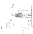
- Fig. 1 shows the SCR system using pressurized air or any other gas in the filling mode.
- Arrows on the simplified flow sheet indicate the actual flow direction through the system.
- the external storage tank (C) contains liquid urea and urea vapour. Liquid urea from (C), which could be the tank station, is transferred to the local tank system (B), which could be on the vehicle by means of an external pump (C1). Transfer pressure is indicated on pressure indicator (P3).
- the 3-way valve (V1) in an "off” position enables urea to flow to the inner part of the membrane (A1). During fill up, air surrounding the membrane is compressed and passes through valve V2, which is also in "off” position, and is led to the surrounding atmosphere through the vent (D). Final fill up is seen when the pressure increases to the same level as the feed pressure from the pump (C1), indicated on pressure indicator (P3).
- Fig. 1 also illustrates the placement of the rubber foam on the inner wall of the membrane storage tank (B). As mentioned earlier, the presence of this material prevents the potentially destructive expansion of the reducing agent, which can be caused by freezing or by heating.
- Fig. 2 shows the system of Fig. 1 using pressurized air in the operation mode.
- Arrows on the flow sheet indicate the actual flow direction.
- the two valves (V1) and (V2) have been turned to an 'on' position, thus reversing the flow direction of the urea.
- air or any other gas is compressed in the compressor (C2) and the compressed air flows through the two reduction valves (R1) and (R2).
- R1 the compressed air flows through valve (V2) into the membrane storage tank (B).
- the pressure is set to for instance 2 bars (2 ⁇ 10 5 Pa), and this is indicated on pressure indicator (P1).
- Urea in the inner bellow (A) is now forced to and through the valve (V1) to the dosing valve (G).
- (G) is electrically operated and the selected urea mass flow is determined by the conditions at this valve. Urea is then sent to the mixer (F). At this point, urea is mixed with air delivered from the reduction valve (R2).
- Fig. 3 shows another embodiment of the invention, where the system is operated in the filling mode using a pressurized liquid as a hydraulic displacement fluid, available on the existing systems in the engine or vehicle.
- the tank (T) can contain either an engine coolant such as water or hydraulic oil, diesel oil, or any other hydraulic displacement fluid.
- an engine coolant such as water or hydraulic oil, diesel oil, or any other hydraulic displacement fluid.
- fill mode the liquid is returned from the membrane tank (B) back to tank (T).
- Other operation parameters are equivalent to the description given for Fig. 1.
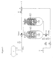
- Fig. 4 shows the system of Fig. 3 in operating mode.
- Liquid from the tank (T) is pumped by the pump (C3) to pressure regulator (R1), where the desired pressure is adjusted.
- the actual pressure is seen on the pressure indicator (P1).
- the liquid passes through the valve (V2) and enters the membrane storage tank (B), causing the reducing agent to leave the inner bellow (A) for the dosing valve (G).
- Fig. 5 shows another embodiment of the invention, where the urea capacity or volume can be doubled or tripled by simply adding additional tanks in series to the system as shown.
- any gas or liquid can be employed as a pneumatic or hydraulic displacement medium for the movement of the reducing agent in and out of the inner bellow (A).
- Displacement media used in this invention include fluids that are available at the actual location where the apparatus is being used. These fluids include gases such as air, carbon dioxide and nitrogen, and liquids such as diesel oil, cooling liquids and hydraulic fluids. Any other gases and liquids can also be used.
- gases such as air, carbon dioxide and nitrogen
- liquids such as diesel oil, cooling liquids and hydraulic fluids. Any other gases and liquids can also be used.
- the reducing agent as used in the following examples covers mixtures of urea or ammonia in water at any given concentration. However, any other reducing agent in any given concentration in water, or any of the above-mentioned liquids either in combinations with each other or neat, can be used. Typical use is 321 ⁇ 2 w/w% urea in water or 25 w/w% ammonia in water.
- the inner bellow (A) was filled with 32.5 w/w% aqueous urea solution.
- the valves (V1) and (V2) were switched to an 'on' position (operation mode).
- the pressure regulator (R1) was adjusted to 2 bar (2 ⁇ 10 5 Pa).
- Carrier air to the mixer (F) was adjusted to 1 bar (1 ⁇ 10 5 Pa) on reduction valve (R2).
- the dosing valve (G) was actuated and constant urea flow to exhaust gas (E) was established.
- the inner bellow (A) was filled with 25% aqueous ammonia. Pressure settings were identical to those of Example 1.
- the dosing valve (G) was actuated and constant ammonia flow was established.
- the system was filled with 32.5 w/w% aqueous urea and then emptied using pressurized air at 2 bars (2 ⁇ 10 5 Pa) in cycles repeated 1000 times.
- the filling time was 5 minutes, the hold time was 1 minute, and emptying time was 7 minutes. No malfunction of the system was observed under these strenuous conditions. Neither were there any visible signs of urea depositions.
- 32.5 w/w% urea crystallizes at -11°C.
- the inner bellow (A) of the storage tank (B) was filled with 32.5 w/w% aqueous urea and put into a freezer for 16 hours at -20°C.
- a temperature indicator was placed inside the membrane in the urea solution. After 16 hours, this indicator showed -19°C.
- the storage tank was then placed at ambient temperature for one day.
- the inner bellow (A) was emptied, separated from the tank and visually inspected. No damage to the inner bellow was observed.
Abstract
Description
- This invention relates to a process for the reduction of nitrogen oxide (NOx) emissions in the exhaust gases of diesel engines or turbines for stationary or mobile applications, and more particularly, to a process suitable for use in a Selective Catalytic Reduction (SCR) system.
- The SCR system represents a known and widely spread technology for the removal of oxides of nitrogen in the exhaust gases from turbines, boilers, burners, power plants and other plants utilizing fossil fuels in the heavy industry. This system is based on the creation of a reducing atmosphere over a catalyst in the presence of the NOx compounds present in the exhaust gases.
- The selection of a reducing agent depends on the local conditions prevailing in the different geographical areas where SCR systems are used. Conditions such as pricing, legislation and logistics play a role in the choice of the reducing agent. Reducing agents that are commonly used with diesel engines are neat or aqueous ammonia (NH3), solid urea (NH2CONH2) or urea dissolved in water.
- Anhydrous ammonia is, however, extremely hazardous, toxic and volatile. On exposure to air, at a sufficiently high temperature and pressure, anhydrous ammonia can combine with air to form a combination that can be lethal. These properties therefore result in problems with the safety aspects where the storage, transportation and handling of large quantities of ammonia are concerned. Urea as a nontoxic alternative to ammonia does not present the same extensive safety problems, and it can be converted to ammonia at a latter stage.
- In the case of ammonia or urea, the reducing agent reacts with NOx compounds such as nitrogen oxide (NO) and nitrogen dioxide (NO2), in the presence of a catalyst, and at normal exhaust gas temperatures of 250-450°C, to liberate free nitrogen (N2) and water. The catalysts used are generally known as DENOX catalysts.
- When the reducing agent is urea, it undergoes pyrolysis at approximately 275°C into gaseous ammonia and cyanuric acid (HNCO) according to the following reaction:
- The HNCO then reacts with the water in the exhaust gas as follows:
- The CO2 does not participate further in the DENOX reaction, whereas the ammonia molecules subsequently react with the nitrogen oxide, NO, on the surface of the catalyst according to the reaction:
- Storage and feeding systems for the selected reducing agent which are used in the various plants, vary in design and construction, but in general, most SCR systems are applied to stationary plants with good infrastructure. Consequently, access to electricity, heat, and sheltered surroundings provide solutions for the safe storage and operation of stationary systems.
- Contrary to the above-mentioned stationary plants are mobile applications such as heavy-duty (HD) truck vehicles operated either on the road, or off road vehicles and equipment. The application of DENOX catalysts for SCR systems to be used in the automotive industry requires that several criteria are fulfilled. These criteria include high resistance to extreme climatic conditions such as subzero temperatures lower than the crystallization point of urea, which is -11°C.
- Resistance to high temperature is also a requirement, since high temperature leads to the reducing agent exhibiting high vapour pressure, and this causes problems during re-fueling and venting of the vehicles. In addition, vehicle vibrations caused during driving also necessitate proper solutions in order to run the operations in a trouble-free manner.
- Thus, there are current demands for high durability and stability when introducing these systems to the automotive industry.
- There have been several attempts to reduce the emissions of NOx from diesel engines.
- US Patent No. 6, 063, 350 discloses a method for SCR NOx emission reduction in an exhaust gas from a lean-burn engine using an aqueous solution of urea. In this system, temperature fluctuations and formation of solid deposits are avoided by monitoring the quality, temperature and level of the urea solution in a storage vessel, using a modular assembly of different sensors mounted inside the urea storage vessel. Based on the sensed parameters, sensor signals are generated compared to reference values, and the flow of urea solution is controlled in response to these signals. A heater can be used to maintain the temperature of the urea solution.
- It also states that precipitation of solids is avoided by recirculating urea through a line between the storage vessel and the injector, which injects urea to the exhaust gases. The rate at which this recirculation takes place helps to maintain the temperature of the urea solution at a sufficiently low level, such that urea is not permitted sufficient time at elevated temperature to hydrolyze to the extent that solids are deposited.
- US Patent No. 6, 209, 315 discloses a method and a device for controlled feeding of a reducing agent in an SCR process for reducing NOx in exhaust gas. The reducing agent is pumped from a storage container to a pressure accumulator inserted between the storage container and the metering valve to the SCR catalyst. The quantity of reducing agent metered may be evaluated from the displacement of a sprung (sprin-loaded) diaphragm in the pressure accumulator in association with a pressure sensor.
- In all tank systems, various types of equipment can be used to avoid freezing of the urea solution. The freezing point of a 32.5 w/w% aqueous urea solution is -11°C. Insulation and various heaters supplied by the battery or other energy sources are mentioned in the prior art. These types of protective equipment are only effective provided a constant power source is available. Loss of battery power in cold weather will cause freezing and crystallization of the urea at sufficiently low temperatures. In ordinary tank systems, damage is seen as a result of the expansion during freezing. The tank and the contents of the tank such as sensors, pumps and other equipment installed inside may then be permanently damaged.
- Several problems associated with the SCR systems currently in use for NOx reductions are corrosion of the different components in the system, crystallization of urea which leads to deposits in the lines, maintaining constant valve settings and unacceptable evaporative emissions. Subzero temperatures also cause freezing followed by destruction of the tank liner pumps. No known system has so far been able to run safely during all the different operating modes.
- It is therefore an object of the invention to provide a safe, reliable SCR system for reducing NOx emissions from diesel systems.
- It is another object of the invention to eliminate the crystallization problems leading to destruction of equipment, associated with freezing of a reducing agent such as urea.
- It is yet another object of the invention to provide simple modular membrane equipment to be used in the SCR system.
- It is yet another specific object of the invention to provide an SCR system in which any type of liquid reducing agent can be used.
- It is yet another specific object of the invention to provide a gas as a pneumatic driving force behind the transfer of the reducing agent.
- It is yet another specific object of the invention to provide a liquid as a hydraulic driving force behind the transfer of the reducing agent.
- These objects are achieved by the present invention, which provides an improved process and a simple modular apparatus for SCR NOx reduction.
- The invention described herein concerns a process for reducing the content of nitrogen oxides (NOx) in the exhaust gases of diesel engines or turbines for stationary or mobile applications/vehicles in an SCR system by providing a stored source of liquid reducing agent and a hydraulic or pneumatic displacement fluid, and feeding the stored reducing agent to the exhaust gases, said process comprising transferring the liquid reducing agent from the external storage tank to one or more membrane storage tanks, each equipped with an inner bellow consisting of a non-permeable flexible membrane, and a hydraulic or pneumatic displacement fluid located outside the inner bellow,
filling up the flexible inner bellow with liquid reducing agent and simultaneously exerting pressure on the displacement fluid in the membrane storage tank until the feeding pressure is attained,
increasing the pressure of the displacement fluid in the membrane storage tank by transferring more fluid into the volume present outside the flexible inner bellow, and thus forcing the liquid reducing agent to leave the flexible inner bellow,
transferring the liquid reducing agent from the flexible inner bellow to the exhaust gases via a dosing valve and a mixing device. - The invention concerns also an apparatus for reducing the content of nitrogen oxides (NOx) in the exhaust gases of diesel engines or turbines for stationary or mobile applications/vehicles in an SCR system, by providing a stored source of liquid reducing agent and feeding the stored reducing agent to the exhaust gases in a process according to
claim 1, the apparatus comprising an external storage tank for storing liquid reducing agent,
one or more membrane storage tanks, each equipped with an inner bellow consisting of a non-permeable flexible membrane, being adapted to expand and contract with the aid of a hydraulic or pneumatic displacement fluid located outside the inner bellow,
a compressing device for the regulation of flow of displacement fluid to and from the membrane storage tank,
a dosing device for regulation of flow of reducing agent to the mixing device,
a mixing device for mixing reducing agent with air. - The process according to the invention utilizes a tank system with a modular membrane unit, which is more beneficial compared to tank systems which do not have such a unit. The use of a gas such as air as a pneumatic force or a liquid as a hydraulic force, eliminates loss of reducing agent due to evaporation during refilling. Non-membrane systems have an equilibrium determined saturated vapour in the air above the reducing agent.
- If urea is used, urea vapour results in urea crystals when the vapour is dried. Deposition of solid urea crystals in the valves, inlets and outlets of the system lead to malfunction of the equipment. When the membrane storage tank is used, the separation of the reducing agent from the air present ensures that no vapour from the reducing agent is present in the air part of the system. Thus, no problems associated with vapour in the air are observed.
- If urea or ammonia is used as a reducing agent, tanks, valves and tubing etc. made of inexpensive brass components cannot be used as they corrode in the presence of these compounds. More expensive types of steel have to be used in the areas subjected to increased pressure. It is, however, not necessary to use steel components in the storage system used in the process according to the invention due to its unique construction and functioning.
- Another advantage of the system used in the process according to the invention is that the membrane tank system is not destroyed if it is accidentally cooled down below the freezing point of the urea solution. The reason for this is that the flexible membrane, containing the reducing agent solution, always has the ability to cope with the expansion of the reducing agent. This ability is obtained by using a flexible material, which can expand and contract. Suitable materials are different types of rubber, for instance EPDM (ethylene propylene diene monomer) rubber. Other types can also be used, provided they are flexible by nature.
- The inner side of the storage tank shell can be coated with foam rubber. A suitable layer of a few millimeters in thickness has shown to be sufficient to absorb the small expansion of the flexible membrane caused by the freezing or crystallisation of urea. No permanent damage of the tank system can thus be induced, and when the temperature exceeds the freezing point of the reducing agent, causing the reducing agent to melt, then the functioning of all equipment is normalised. To avoid freezing, precautions similar to those used for non-membrane systems may be used for example heating.
-
- Fig. 1 is a flow diagram showing the operation of the SCR system using pressurized air or gas in the filling mode.
- Fig. 2 shows the system of Fig. 1 using pressurized air or gas in the operation mode.
- Fig. 3 shows the operation of the SCR system using pressurized liquid in the filling mode.
- Fig. 4 shows the system of Fig. 3 using pressurized liquid in the operation mode.
- Fig. 5 shows a system with increased tank capacity.
-
- The apparatus consists of an external tank (C) and a membrane storage tank (B) with an in-built inner bellow (A), the inner bellow (A) being constructed from a non-permeable flexible membrane (A1). A unit (H) for compressed air or any other gas to be used for pneumatic displacement, and a tank (T) for diesel oil or any other fluid to be used for hydraulic displacement, are also present.
- In addition there is a 3-way valve (V1) for the entrance and exit of reducing agent to the membrane storage tank, another 3-way valve (V2) allowing the displacement fluid to enter or exit the membrane storage tank, and a number of pressure indicators and reduction valves. A dosing valve (G) for transferring the reducing agent to a mixing device (F) is also present. Finally the reducing agent enters the exhaust gas stream (E).
- A suitable mixing device could be of the type having a combined silencing and mixing effect such as the device described in EP patent application No. 960,650.
- The figures are explained using urea as an example of a reducing agent. Any other reducing agent could be used in place of urea.
- Fig. 1 shows the SCR system using pressurized air or any other gas in the filling mode. Arrows on the simplified flow sheet indicate the actual flow direction through the system. The external storage tank (C) contains liquid urea and urea vapour. Liquid urea from (C), which could be the tank station, is transferred to the local tank system (B), which could be on the vehicle by means of an external pump (C1). Transfer pressure is indicated on pressure indicator (P3). The 3-way valve (V1) in an "off" position enables urea to flow to the inner part of the membrane (A1). During fill up, air surrounding the membrane is compressed and passes through valve V2, which is also in "off" position, and is led to the surrounding atmosphere through the vent (D). Final fill up is seen when the pressure increases to the same level as the feed pressure from the pump (C1), indicated on pressure indicator (P3).
- Fig. 1 also illustrates the placement of the rubber foam on the inner wall of the membrane storage tank (B). As mentioned earlier, the presence of this material prevents the potentially destructive expansion of the reducing agent, which can be caused by freezing or by heating.
- Fig. 2 shows the system of Fig. 1 using pressurized air in the operation mode. Arrows on the flow sheet indicate the actual flow direction. The two valves (V1) and (V2) have been turned to an 'on' position, thus reversing the flow direction of the urea. In this case, air or any other gas is compressed in the compressor (C2) and the compressed air flows through the two reduction valves (R1) and (R2). From (R1), the compressed air flows through valve (V2) into the membrane storage tank (B). On the reduction valve (R1) the pressure is set to for instance 2 bars (2·105 Pa), and this is indicated on pressure indicator (P1). Urea in the inner bellow (A) is now forced to and through the valve (V1) to the dosing valve (G). (G) is electrically operated and the selected urea mass flow is determined by the conditions at this valve. Urea is then sent to the mixer (F). At this point, urea is mixed with air delivered from the reduction valve (R2).
- This results in a homogeneous controlled mixture being delivered to the exhaust gas (E). Pressure is regulated to, for instance, 1 bar (1·105 Pa), as shown on the pressure indicator (P2). The final urea/air mixture is now ready to be delivered to the exhaust gas (E).
- Fig. 3 shows another embodiment of the invention, where the system is operated in the filling mode using a pressurized liquid as a hydraulic displacement fluid, available on the existing systems in the engine or vehicle. The tank (T) can contain either an engine coolant such as water or hydraulic oil, diesel oil, or any other hydraulic displacement fluid. In fill mode the liquid is returned from the membrane tank (B) back to tank (T). Other operation parameters are equivalent to the description given for Fig. 1.
- Fig. 4 shows the system of Fig. 3 in operating mode. Liquid from the tank (T) is pumped by the pump (C3) to pressure regulator (R1), where the desired pressure is adjusted. The actual pressure is seen on the pressure indicator (P1). The liquid passes through the valve (V2) and enters the membrane storage tank (B), causing the reducing agent to leave the inner bellow (A) for the dosing valve (G).
- Other operation parameters are equivalent to the description given for Fig. 2.
- Fig. 5 shows another embodiment of the invention, where the urea capacity or volume can be doubled or tripled by simply adding additional tanks in series to the system as shown.
- With reference to the above, it can be seen that air is eliminated from the system, once the reducing agent is withdrawn from the tank (C), thus increasing the safety aspects of the apparatus.
- It is also obvious that any gas or liquid can be employed as a pneumatic or hydraulic displacement medium for the movement of the reducing agent in and out of the inner bellow (A).
- Displacement media used in this invention include fluids that are available at the actual location where the apparatus is being used. These fluids include gases such as air, carbon dioxide and nitrogen, and liquids such as diesel oil, cooling liquids and hydraulic fluids. Any other gases and liquids can also be used.
- In the following examples a tank (B) equipped with an inner bellow (A) made of a flexible EPDM rubber membrane (A1) was tested.
- The reducing agent as used in the following examples covers mixtures of urea or ammonia in water at any given concentration. However, any other reducing agent in any given concentration in water, or any of the above-mentioned liquids either in combinations with each other or neat, can be used. Typical use is 32½ w/w% urea in water or 25 w/w% ammonia in water.
- A system as described above was built and tested. The inner bellow (A) was filled with 32.5 w/w% aqueous urea solution. The valves (V1) and (V2) were switched to an 'on' position (operation mode). The pressure regulator (R1) was adjusted to 2 bar (2·105 Pa). Carrier air to the mixer (F) was adjusted to 1 bar (1·105 Pa) on reduction valve (R2). The dosing valve (G) was actuated and constant urea flow to exhaust gas (E) was established.
- Instead of urea solution, the inner bellow (A) was filled with 25% aqueous ammonia. Pressure settings were identical to those of Example 1. The dosing valve (G) was actuated and constant ammonia flow was established.
- As in Example 1, but in this case coolant liquid from tank (T) was used instead of compressed air. Coolant was pumped via the pump (C3). The stream pressure was adjusted on reduction valve (R1) to 2 bar (2·105 Pa) as shown on the pressure indicator (P1). The liquid flow was sent through (V2), which was in an "on" position to tank (B). Urea contained in the inner bellow (A) was pressurized to the equivalent pressure of 2 bar (2·105 Pa). Urea flow to the mixer (F) was established as in Example 1.
- As in Example 3, but using diesel oil instead of coolant in tank (T). Flow was established as in the previous Example.
- As in Example 3, but using hydraulic oil instead of coolant in tank (T). Flow was also established.
- The system was filled with 32.5 w/w% aqueous urea and then emptied using pressurized air at 2 bars (2·105 Pa) in cycles repeated 1000 times. The filling time was 5 minutes, the hold time was 1 minute, and emptying time was 7 minutes. No malfunction of the system was observed under these strenuous conditions. Neither were there any visible signs of urea depositions.
- 32.5 w/w% urea crystallizes at -11°C. In order to determine the membrane storage tank's resistance to extremely cold conditions, the inner bellow (A) of the storage tank (B) was filled with 32.5 w/w% aqueous urea and put into a freezer for 16 hours at -20°C. A temperature indicator was placed inside the membrane in the urea solution. After 16 hours, this indicator showed -19°C. The storage tank was then placed at ambient temperature for one day. The inner bellow (A) was emptied, separated from the tank and visually inspected. No damage to the inner bellow was observed.
Claims (10)
- A process for reducing the content of nitrogen oxides (NOx) in the exhaust gases of diesel engines or turbines for stationary or mobile applications/vehicles in an SCR system by providing a stored source of liquid reducing agent and feeding the stored reducing agent to the exhaust gases, said process comprising
transferring the liquid reducing agent from an external storage tank to one or more membrane storage tanks, each equipped with an inner bellow consisting of a non-permeable flexible membrane, and a hydraulic or pneumatic displacement fluid located outside the inner bellow,
filling the flexible inner bellow with liquid reducing agent and simultaneously exerting pressure on the displacement fluid in the membrane storage tank until the feeding pressure is attained,
increasing the pressure of the displacement fluid in the membrane storage tank by transferring more fluid into the volume present outside the flexible inner bellow, and thus forcing the liquid reducing agent to leave the flexible inner bellow,
transferring the liquid reducing agent from the flexible inner bellow to the exhaust gases. - A process as specified in claim 1, wherein said fluid used for the pneumatic or hydraulic displacement of liquid reducing agent present in the flexible inner tank, is a gas or a liquid, respectively.
- A process as specified in claim 1, wherein said fluid used for the pneumatic displacement of liquid reducing agent in the flexible inner tank is compressed air.
- A process as specified in claim 1, wherein said fluid used for the hydraulic displacement of liquid reducing agent in the flexible inner tank is cooling liquid.
- A process as specified in claim 1, wherein said fluid used for the hydraulic displacement of liquid reducing agent in the flexible inner tank, is diesel oil.
- A process as specified in claim 1, wherein at least two membrane storage tanks in series are available for storage of the liquid reducing agent.
- A process as specified in claims 1-6, wherein the liquid reducing agent is aqueous urea or ammonia.
- An apparatus for reducing the content of nitrogen oxides (NOx) in the exhaust gases of diesel engines or turbines for stationary or mobile applications/vehicles in an SCR system, by providing a stored source of liquid reducing agent and feeding the stored reducing agent to the exhaust gases, in a process according to claim 1, the apparatus comprising,
an external storage tank for storing liquid reducing agent,
one or more membrane storage tanks, each equipped with an inner bellow consisting of a non-permeable flexible membrane, being adapted to expand and contract with the aid of a hydraulic or pneumatic displacement fluid located outside the inner bellow,
compressing device for the regulation of flow of displacement fluid to and from the membrane storage tank,
dosing device for regulation of flow of reducing agent,
mixing device for mixing reducing agent with air. - An apparatus as specified in claim 8, wherein the membrane storage tank is built into the diesel tank of the engine.
- An apparatus as specified in claim 8, wherein the membrane storage tank is built into the cooling system of the engine.
Applications Claiming Priority (2)
| Application Number | Priority Date | Filing Date | Title |
|---|---|---|---|
| DK200100345 | 2001-03-02 | ||
| DKPA200100345 | 2001-03-02 |
Publications (2)
| Publication Number | Publication Date |
|---|---|
| EP1236499A1 EP1236499A1 (en) | 2002-09-04 |
| EP1236499B1 true EP1236499B1 (en) | 2004-05-19 |
Family
ID=8160338
Family Applications (1)
| Application Number | Title | Priority Date | Filing Date |
|---|---|---|---|
| EP02003645A Expired - Lifetime EP1236499B1 (en) | 2001-03-02 | 2002-02-18 | SCR process and apparatus for the reduction of NOx emissions |
Country Status (8)
| Country | Link |
|---|---|
| US (1) | US6550250B2 (en) |
| EP (1) | EP1236499B1 (en) |
| JP (1) | JP2002327617A (en) |
| CN (1) | CN1245244C (en) |
| AT (1) | ATE267041T1 (en) |
| CA (1) | CA2374253C (en) |
| DE (1) | DE60200491T2 (en) |
| RU (1) | RU2002105456A (en) |
Cited By (7)
| Publication number | Priority date | Publication date | Assignee | Title |
|---|---|---|---|---|
| WO2010049022A1 (en) * | 2008-10-27 | 2010-05-06 | Albonair Gmbh | Metering system |
| US8074673B2 (en) | 2004-05-18 | 2011-12-13 | Hydraulik-Ring Gmbh | Freeze-resistant metering valve |
| US8201393B2 (en) | 2008-03-05 | 2012-06-19 | Hilite Germany Gmbh | Exhaust-gas aftertreatment device |
| RU2459978C1 (en) * | 2011-07-26 | 2012-08-27 | Общество с ограниченной ответственностью "Купер" | Adjustable diaphragm pump unit |
| US8266892B2 (en) | 2007-01-25 | 2012-09-18 | Friedrich Zapf | Calibrated dosing unit, especially of an exhaust gas treatment unit |
| US8875502B2 (en) | 2010-12-14 | 2014-11-04 | Cummins Ltd. | SCR exhaust gas aftertreatment device |
| US8938949B2 (en) | 2009-08-03 | 2015-01-27 | Cummins Ltd. | SCR exhaust gas aftertreatment device |
Families Citing this family (83)
| Publication number | Priority date | Publication date | Assignee | Title |
|---|---|---|---|---|
| DE10127834A1 (en) * | 2001-06-08 | 2002-12-12 | Bosch Gmbh Robert | Device for dosing a reducing agent, especially urea or a urea-water solution, comprises units for introducing the agent into a catalyst arrangement, a dosing valve arranged at the end |
| DE10312102B4 (en) * | 2003-03-19 | 2015-10-08 | Robert Bosch Gmbh | Device for measuring a level of a liquid in a container |
| DE10316184A1 (en) * | 2003-04-09 | 2004-10-28 | Robert Bosch Gmbh | Method for metering a reagent into the exhaust gas stream of an internal combustion engine |
| DE10346220A1 (en) * | 2003-09-23 | 2005-04-14 | Robert Bosch Gmbh | Fuel injection combustion engine with exhaust gas treatment has a pressure accumulator for use with a reducing agent storage and injection system for spraying the agent into the exhaust gas |
| SE526072C2 (en) * | 2003-12-04 | 2005-06-28 | Volvo Lastvagnar Ab | Heating device |
| DE102004006333B4 (en) * | 2004-02-10 | 2008-01-03 | Hydraulik-Ring Gmbh | Intermediate accumulator for an exhaust aftertreatment medium of an exhaust aftertreatment device for vehicles with diesel internal combustion engines |
| US7776265B2 (en) * | 2004-03-18 | 2010-08-17 | Cummins Filtration Ip, Inc. | System for diagnosing reagent solution quality |
| JP4137838B2 (en) * | 2004-04-30 | 2008-08-20 | ボッシュ株式会社 | Liquid supply device for exhaust gas aftertreatment device |
| FR2870172B1 (en) * | 2004-05-13 | 2006-07-07 | Inergy Automotive Systems Res | ADDITIVE TANK FOR A VEHICLE HAVING AN INTERNAL COMBUSTION ENGINE |
| ITMI20041318A1 (en) | 2004-06-30 | 2004-09-30 | Iveco Spa | EQUIPMENT AND METHOD FOR INJECTION OF A LIQUID TO A GASEOUS CURRENT EXHAUST GAS TREATMENT PLANT AND VEHICLE EQUIPPED WITH SUCH SYSTEM |
| JP4541069B2 (en) * | 2004-08-09 | 2010-09-08 | 東京エレクトロン株式会社 | Chemical supply system |
| US7498009B2 (en) * | 2004-08-16 | 2009-03-03 | Dana Uv, Inc. | Controlled spectrum ultraviolet radiation pollution control process |
| JP4290110B2 (en) * | 2004-11-04 | 2009-07-01 | 日産ディーゼル工業株式会社 | Exhaust purification equipment |
| DE102004063071B4 (en) * | 2004-12-28 | 2021-10-14 | Robert Bosch Gmbh | Vehicle with a supply unit |
| DE102005006243B4 (en) * | 2005-02-11 | 2007-05-31 | Daimlerchrysler Ag | Motor vehicle with internal combustion engine and emission control system |
| US20070163245A1 (en) * | 2006-01-19 | 2007-07-19 | Sheridan Todd A | Reagent refill and supply system for an SCR exhaust aftertreatment system |
| DE102006019051A1 (en) * | 2006-04-25 | 2007-10-31 | Robert Bosch Gmbh | Device for supplying a reducing agent in an exhaust line of an internal combustion engine |
| US20070289288A1 (en) * | 2006-06-19 | 2007-12-20 | Ford Global Technologies, Llc | Venting of on-board vehicle emissions treatment system with pressure assist |
| DE102007005004A1 (en) * | 2007-02-01 | 2008-08-07 | Bayerische Motoren Werke Aktiengesellschaft | Feeding device for a liquid additive for an internal combustion engine |
| DE102007005006A1 (en) * | 2007-02-01 | 2008-08-07 | Bayerische Motoren Werke Aktiengesellschaft | Device for supplying a liquid additive for an internal combustion engine |
| FR2912932B1 (en) * | 2007-02-23 | 2011-06-10 | Total France | AQUEOUS SOLUTION FOR THE TREATMENT OF EXHAUST GASES FROM DIESEL ENGINES |
| FR2914013A1 (en) * | 2007-03-22 | 2008-09-26 | Peugeot Citroen Automobiles Sa | LOW TEMPERATURE UREA INJECTION PROCESS |
| JP5028165B2 (en) * | 2007-07-03 | 2012-09-19 | 日立建機株式会社 | Engine powered machine |
| EP2014886A1 (en) * | 2007-07-09 | 2009-01-14 | Delphi Technologies, Inc. | Reservoir for a fluid dosing system |
| US20090103838A1 (en) * | 2007-10-17 | 2009-04-23 | Caterpillar Inc. | Collapsible fluid storage tank |
| DE102008005759A1 (en) * | 2008-01-24 | 2009-07-30 | Volkswagen Ag | Storage vessel for storage of hygroscopic solid provided in division level, has partial volume of interior space of storage vessel, where solid is stored |
| US8141353B2 (en) * | 2008-04-25 | 2012-03-27 | Tenneco Automotive Operating Company Inc. | Exhaust gas additive/treatment system and mixer for use therein |
| US8201394B2 (en) | 2008-04-30 | 2012-06-19 | Cummins Ip, Inc. | Apparatus, system, and method for NOx signal correction in feedback controls of an SCR system |
| US8505278B2 (en) | 2009-04-30 | 2013-08-13 | Cummins Ip, Inc. | Engine system properties controller |
| US8161730B2 (en) | 2008-04-30 | 2012-04-24 | Cummins Ip, Inc. | Apparatus, system, and method for reducing NOx emissions on an SCR catalyst |
| US8181450B2 (en) | 2008-04-30 | 2012-05-22 | Cummins IP. Inc. | Apparatus, system, and method for reducing NOx emissions on an SCR catalyst using ammonia storage and slip control |
| US8109079B2 (en) | 2008-04-30 | 2012-02-07 | Cummins Ip, Inc. | Apparatus, system, and method for controlling ammonia slip from an SCR catalyst |
| WO2009135071A2 (en) * | 2008-04-30 | 2009-11-05 | Cummins Ip, Inc. | Apparatus, system, and method for reducing nox emissions from an engine system |
| US8281572B2 (en) | 2008-04-30 | 2012-10-09 | Cummins Ip, Inc. | Apparatus, system, and method for reducing NOx emissions from an engine system |
| US8074445B2 (en) | 2008-04-30 | 2011-12-13 | Cummins Ip, Inc. | Apparatus, system, and method for reducing NOx emissions on an SCR catalyst |
| US8141340B2 (en) | 2008-04-30 | 2012-03-27 | Cummins Ip, Inc | Apparatus, system, and method for determining the degradation of an SCR catalyst |
| DE102008023437B4 (en) * | 2008-05-14 | 2012-12-06 | Pierburg Gmbh | Motor vehicle SCR particulate storage assembly |
| CN101660443B (en) * | 2008-05-28 | 2011-08-10 | 中国第一汽车集团公司 | Vehicle-mounted SCR metering and ejecting system taking exhaust gas temperature as variable |
| DE102008030756A1 (en) * | 2008-06-27 | 2010-01-07 | Emitec Gesellschaft Für Emissionstechnologie Mbh | Method for operating a HWL dosing system |
| DE102008044708A1 (en) * | 2008-08-28 | 2010-03-04 | Emitec Gesellschaft Für Emissionstechnologie Mbh | SCR system with compensation element |
| DE102008049097A1 (en) | 2008-09-26 | 2010-04-01 | Daimler Ag | A motor vehicle with a system for supplying liquid into another medium, in particular for supplying a reducing agent into the exhaust gas of an internal combustion engine |
| WO2010065965A2 (en) | 2008-12-05 | 2010-06-10 | Cummins Ip, Inc. | Apparatus, system, and method for controlling reductant dosing in an scr catalyst system |
| WO2010065963A2 (en) | 2008-12-05 | 2010-06-10 | Cummins Ip, Inc. | Apparatus, system, and method for estimating an nox conversion efficiency of a selective catalytic reduction catalyst |
| DE102009009899A1 (en) * | 2009-02-20 | 2010-08-26 | Bayerische Motoren Werke Aktiengesellschaft | Motor vehicle, has inner container part whose wall lies on outer part under influence of frozen urea solution if urea solution is in partially frozen state and inner container part experiences volume expansion |
| FR2943999A1 (en) * | 2009-04-02 | 2010-10-08 | Peugeot Citroen Automobiles Sa | UREE TANK, EXHAUST LINE AND VEHICLE |
| DE102009024965B4 (en) * | 2009-06-12 | 2021-03-18 | Dürr Somac GmbH | Filling device |
| FR2949503B1 (en) * | 2009-08-27 | 2012-11-16 | Coutier Moulage Gen Ind | FLEXIBLE TANK FOR ADDITIVE PRODUCT |
| FR2949504B1 (en) * | 2009-08-27 | 2012-11-16 | Coutier Moulage Gen Ind | FLEXIBLE TANK FOR ADDITIVE PRODUCT |
| WO2011032020A2 (en) | 2009-09-10 | 2011-03-17 | Cummins Ip, Inc. | Low temperature selective catalytic reduction catalyst and associated systems and methods |
| US8733083B2 (en) | 2010-04-26 | 2014-05-27 | Cummins Filtration Ip, Inc. | SCR catalyst ammonia surface coverage estimation and control |
| CN102400742B (en) * | 2010-09-07 | 2013-12-25 | 博世汽车柴油系统股份有限公司 | Vehicle SCR (Selective Catalytic Reduction) system and reducing agent supply device thereof |
| FR2965295B1 (en) * | 2010-09-28 | 2012-09-28 | Peugeot Citroen Automobiles Sa | METHOD FOR STARTING A SELECTIVE CATALYTIC REDUCTION SYSTEM FOR A VEHICLE, SYSTEM AND VEHICLE THEREFOR |
| US8495869B2 (en) | 2010-11-02 | 2013-07-30 | Girtz Industries Inc. | Power systems with internally integrated aftertreatment and modular features |
| CN102102566B (en) * | 2010-12-29 | 2013-04-03 | 潍柴动力股份有限公司 | Transient compensation method and system for nitrogen oxide discharging of automobile engine |
| DE102011014026A1 (en) * | 2011-03-15 | 2012-09-20 | Albonair Gmbh | reducer |
| BE1019966A3 (en) * | 2011-05-03 | 2013-03-05 | Inergy Automotive Systems Res | TUBE FOR A FLUID SYSTEM IN A VEHICLE. |
| EP2522823B1 (en) * | 2011-05-13 | 2014-04-23 | Aaqius & Aaqius S.A. | Device for measuring an amount of a reducing agent, preferably NH3, contained in a tank |
| US8881507B2 (en) * | 2011-08-22 | 2014-11-11 | Mi Yan | Air driven reductant delivery system |
| US20150283505A1 (en) * | 2012-11-09 | 2015-10-08 | Mack Trucks, Inc. | Method and apparatus for urea conditioning and injection control in a selective catalytic reduction system |
| EP2829699A1 (en) * | 2013-07-24 | 2015-01-28 | Inergy Automotive Systems Research (Société Anonyme) | Engine exhaust gas additive storage system |
| US9429060B2 (en) | 2013-10-28 | 2016-08-30 | Cummins Emission Solutions Inc. | Systems and methods for control of engine NOx emissions using liquid and dry reductant sources |
| US10060316B2 (en) | 2015-06-29 | 2018-08-28 | General Electric Company | Power generation system exhaust cooling |
| US9850794B2 (en) | 2015-06-29 | 2017-12-26 | General Electric Company | Power generation system exhaust cooling |
| US9752503B2 (en) | 2015-06-29 | 2017-09-05 | General Electric Company | Power generation system exhaust cooling |
| US10087801B2 (en) | 2015-06-29 | 2018-10-02 | General Electric Company | Power generation system exhaust cooling |
| US10030558B2 (en) | 2015-06-29 | 2018-07-24 | General Electric Company | Power generation system exhaust cooling |
| US9840953B2 (en) | 2015-06-29 | 2017-12-12 | General Electric Company | Power generation system exhaust cooling |
| US9938874B2 (en) | 2015-06-29 | 2018-04-10 | General Electric Company | Power generation system exhaust cooling |
| US9752502B2 (en) | 2015-06-29 | 2017-09-05 | General Electric Company | Power generation system exhaust cooling |
| US9850818B2 (en) | 2015-06-29 | 2017-12-26 | General Electric Company | Power generation system exhaust cooling |
| US10215070B2 (en) | 2015-06-29 | 2019-02-26 | General Electric Company | Power generation system exhaust cooling |
| US10077694B2 (en) | 2015-06-29 | 2018-09-18 | General Electric Company | Power generation system exhaust cooling |
| US9856768B2 (en) * | 2015-06-29 | 2018-01-02 | General Electric Company | Power generation system exhaust cooling |
| CN105545422B (en) * | 2016-02-05 | 2018-01-30 | 东风商用车有限公司 | A kind of air-assisted atomized urea spraying system and its control method |
| CN105545423B (en) * | 2016-02-05 | 2018-01-30 | 东风商用车有限公司 | One kind is without air-assisted atomized urea spraying system and its control method |
| DE102016204691A1 (en) * | 2016-03-22 | 2017-09-28 | Volkswagen Aktiengesellschaft | Apparatus and method for regeneration of a particulate filter |
| US10316759B2 (en) | 2016-05-31 | 2019-06-11 | General Electric Company | Power generation system exhaust cooling |
| US11028752B2 (en) * | 2018-02-12 | 2021-06-08 | Cummins Emission Solutions Inc. | Reductant insertion assembly comprising a bladder |
| CN108301906B (en) * | 2018-03-21 | 2023-11-03 | 武汉洛特福动力技术有限公司 | Air pressurization infiltration belt cleaning device |
| GB2591678B (en) * | 2018-10-02 | 2022-11-23 | Cummins Emission Solutions Inc | Systems and methods for dry chemical reductant insertion in aftertreatment systems |
| US11867111B2 (en) | 2019-05-09 | 2024-01-09 | Cummins Emission Solutions Inc. | Valve arrangement for split-flow close-coupled catalyst |
| US11732628B1 (en) | 2020-08-12 | 2023-08-22 | Old World Industries, Llc | Diesel exhaust fluid |
| US11635010B1 (en) | 2021-10-05 | 2023-04-25 | Umicore Ag & Co. Kg | Combustion turbine and heat recovery system combination with SCR reactor assembly, and methods of assembling and using the same |
Family Cites Families (10)
| Publication number | Priority date | Publication date | Assignee | Title |
|---|---|---|---|---|
| DE1172910B (en) | 1957-07-11 | 1964-06-25 | Olaer Patent Co | Pressure vessel |
| GB840259A (en) | 1958-09-04 | 1960-07-06 | Greer Hydraulics Inc | Gas pressure booster system |
| JPH02207119A (en) | 1989-02-06 | 1990-08-16 | Shinko Electric Co Ltd | Denitrating device for exhaust gas of engine |
| US5709080A (en) * | 1996-03-15 | 1998-01-20 | Caterpillar Inc. | Leak detection method and apparatus for an exhaust purification system |
| DE19629163C1 (en) * | 1996-07-19 | 1997-10-09 | Daimler Benz Ag | Diesel engine operation to suppress nitrogen oxides emission |
| US6063350A (en) * | 1997-04-02 | 2000-05-16 | Clean Diesel Technologies, Inc. | Reducing nox emissions from an engine by temperature-controlled urea injection for selective catalytic reduction |
| DE19726392A1 (en) * | 1997-06-21 | 1998-12-24 | Bosch Gmbh Robert | Mixture dispenser |
| DE19819579C1 (en) | 1998-04-30 | 1999-09-30 | Siemens Ag | Secondary treatment of exhaust from lean burn diesel engine with SCR catalyst, minimizing pump usage and energy consumption |
| US6273120B1 (en) * | 1998-11-12 | 2001-08-14 | Siemens Aktiengesellschaft | Device for introducing a liquid reducing agent into an exhaust gas purification system |
| US6427439B1 (en) * | 2000-07-13 | 2002-08-06 | Ford Global Technologies, Inc. | Method and system for NOx reduction |
-
2002
- 2002-02-18 AT AT02003645T patent/ATE267041T1/en not_active IP Right Cessation
- 2002-02-18 DE DE60200491T patent/DE60200491T2/en not_active Expired - Lifetime
- 2002-02-18 EP EP02003645A patent/EP1236499B1/en not_active Expired - Lifetime
- 2002-02-22 US US10/079,421 patent/US6550250B2/en not_active Expired - Lifetime
- 2002-03-01 JP JP2002056250A patent/JP2002327617A/en active Pending
- 2002-03-01 CN CNB021064180A patent/CN1245244C/en not_active Expired - Fee Related
- 2002-03-01 CA CA002374253A patent/CA2374253C/en not_active Expired - Fee Related
- 2002-03-04 RU RU2002105456/06A patent/RU2002105456A/en not_active Application Discontinuation
Cited By (9)
| Publication number | Priority date | Publication date | Assignee | Title |
|---|---|---|---|---|
| US8074673B2 (en) | 2004-05-18 | 2011-12-13 | Hydraulik-Ring Gmbh | Freeze-resistant metering valve |
| US8266892B2 (en) | 2007-01-25 | 2012-09-18 | Friedrich Zapf | Calibrated dosing unit, especially of an exhaust gas treatment unit |
| US8875491B2 (en) | 2007-01-25 | 2014-11-04 | Cummins Ltd. | Exhaust gas aftertreatment system and method |
| US8201393B2 (en) | 2008-03-05 | 2012-06-19 | Hilite Germany Gmbh | Exhaust-gas aftertreatment device |
| US8959895B2 (en) | 2008-03-05 | 2015-02-24 | Cummins Ltd. | Exhaust-gas aftertreatment device |
| WO2010049022A1 (en) * | 2008-10-27 | 2010-05-06 | Albonair Gmbh | Metering system |
| US8938949B2 (en) | 2009-08-03 | 2015-01-27 | Cummins Ltd. | SCR exhaust gas aftertreatment device |
| US8875502B2 (en) | 2010-12-14 | 2014-11-04 | Cummins Ltd. | SCR exhaust gas aftertreatment device |
| RU2459978C1 (en) * | 2011-07-26 | 2012-08-27 | Общество с ограниченной ответственностью "Купер" | Adjustable diaphragm pump unit |
Also Published As
| Publication number | Publication date |
|---|---|
| EP1236499A1 (en) | 2002-09-04 |
| US20020124568A1 (en) | 2002-09-12 |
| US6550250B2 (en) | 2003-04-22 |
| CA2374253A1 (en) | 2002-09-07 |
| DE60200491D1 (en) | 2004-06-24 |
| DE60200491T2 (en) | 2005-06-09 |
| CN1382517A (en) | 2002-12-04 |
| CA2374253C (en) | 2009-10-27 |
| RU2002105456A (en) | 2003-09-10 |
| CN1245244C (en) | 2006-03-15 |
| ATE267041T1 (en) | 2004-06-15 |
| JP2002327617A (en) | 2002-11-15 |
Similar Documents
| Publication | Publication Date | Title |
|---|---|---|
| EP1236499B1 (en) | SCR process and apparatus for the reduction of NOx emissions | |
| US7818961B2 (en) | System for storing an additive and for injecting it into engine exhaust gases | |
| US6387336B2 (en) | Method and device for selective catalytic NOx reduction | |
| US7497075B2 (en) | Method and device for storing and dosing a reducing agent | |
| US9803530B2 (en) | Liquid reservoir, in particular for an aqueous urea solution | |
| US10695719B2 (en) | Producing ammonium carbamate and reducing nitrogen oxides | |
| EP2057046B1 (en) | Line equipped with a coupling having an integrated heating element | |
| US7497076B2 (en) | Emission control system | |
| EP2014886A1 (en) | Reservoir for a fluid dosing system | |
| US8424724B2 (en) | System for storing an additive solution and injecting it into the exhaust gases of an engine | |
| WO2008058977A1 (en) | System for storing an additive and injecting it into the exhaust gases of an engine | |
| EP2941551B1 (en) | Method and system for generating power on board a vehicle | |
| WO2012134516A1 (en) | Status indicator for ammonia cartridge | |
| EP3480438B1 (en) | Device to supply an internal combustion engine with water coming from a tank of an exhaust system provided with exhaust gas after-treatment | |
| US11788452B2 (en) | Tank for a liquid solution | |
| Thompson et al. | Case studies of urea SCR integration on passenger cars monitoring of urea inside the tank during hot and cold environment test missions | |
| WO2006067075A1 (en) | Pressure switch with integrated power relay |
Legal Events
| Date | Code | Title | Description |
|---|---|---|---|
| PUAI | Public reference made under article 153(3) epc to a published international application that has entered the european phase |
Free format text: ORIGINAL CODE: 0009012 |
|
| AK | Designated contracting states |
Kind code of ref document: A1 Designated state(s): AT BE CH CY DE DK ES FI FR GB GR IE IT LI LU MC NL PT SE TR |
|
| AX | Request for extension of the european patent |
Free format text: AL;LT;LV;MK;RO;SI |
|
| 17P | Request for examination filed |
Effective date: 20030304 |
|
| AKX | Designation fees paid |
Designated state(s): AT BE CH CY DE DK ES FI FR GB GR IE IT LI LU MC NL PT SE TR |
|
| GRAP | Despatch of communication of intention to grant a patent |
Free format text: ORIGINAL CODE: EPIDOSNIGR1 |
|
| GRAS | Grant fee paid |
Free format text: ORIGINAL CODE: EPIDOSNIGR3 |
|
| GRAA | (expected) grant |
Free format text: ORIGINAL CODE: 0009210 |
|
| AK | Designated contracting states |
Kind code of ref document: B1 Designated state(s): AT BE CH CY DE DK ES FI FR GB GR IE IT LI LU MC NL PT SE TR |
|
| PG25 | Lapsed in a contracting state [announced via postgrant information from national office to epo] |
Ref country code: FI Free format text: LAPSE BECAUSE OF FAILURE TO SUBMIT A TRANSLATION OF THE DESCRIPTION OR TO PAY THE FEE WITHIN THE PRESCRIBED TIME-LIMIT Effective date: 20040519 Ref country code: AT Free format text: LAPSE BECAUSE OF FAILURE TO SUBMIT A TRANSLATION OF THE DESCRIPTION OR TO PAY THE FEE WITHIN THE PRESCRIBED TIME-LIMIT Effective date: 20040519 Ref country code: LI Free format text: LAPSE BECAUSE OF FAILURE TO SUBMIT A TRANSLATION OF THE DESCRIPTION OR TO PAY THE FEE WITHIN THE PRESCRIBED TIME-LIMIT Effective date: 20040519 Ref country code: BE Free format text: LAPSE BECAUSE OF FAILURE TO SUBMIT A TRANSLATION OF THE DESCRIPTION OR TO PAY THE FEE WITHIN THE PRESCRIBED TIME-LIMIT Effective date: 20040519 Ref country code: NL Free format text: LAPSE BECAUSE OF FAILURE TO SUBMIT A TRANSLATION OF THE DESCRIPTION OR TO PAY THE FEE WITHIN THE PRESCRIBED TIME-LIMIT Effective date: 20040519 Ref country code: CH Free format text: LAPSE BECAUSE OF FAILURE TO SUBMIT A TRANSLATION OF THE DESCRIPTION OR TO PAY THE FEE WITHIN THE PRESCRIBED TIME-LIMIT Effective date: 20040519 Ref country code: TR Free format text: LAPSE BECAUSE OF FAILURE TO SUBMIT A TRANSLATION OF THE DESCRIPTION OR TO PAY THE FEE WITHIN THE PRESCRIBED TIME-LIMIT Effective date: 20040519 |
|
| REG | Reference to a national code |
Ref country code: GB Ref legal event code: FG4D |
|
| REG | Reference to a national code |
Ref country code: CH Ref legal event code: EP |
|
| REG | Reference to a national code |
Ref country code: IE Ref legal event code: FG4D |
|
| REF | Corresponds to: |
Ref document number: 60200491 Country of ref document: DE Date of ref document: 20040624 Kind code of ref document: P |
|
| REG | Reference to a national code |
Ref country code: SE Ref legal event code: TRGR |
|
| PG25 | Lapsed in a contracting state [announced via postgrant information from national office to epo] |
Ref country code: DK Free format text: LAPSE BECAUSE OF FAILURE TO SUBMIT A TRANSLATION OF THE DESCRIPTION OR TO PAY THE FEE WITHIN THE PRESCRIBED TIME-LIMIT Effective date: 20040819 Ref country code: GR Free format text: LAPSE BECAUSE OF FAILURE TO SUBMIT A TRANSLATION OF THE DESCRIPTION OR TO PAY THE FEE WITHIN THE PRESCRIBED TIME-LIMIT Effective date: 20040819 |
|
| PG25 | Lapsed in a contracting state [announced via postgrant information from national office to epo] |
Ref country code: ES Free format text: LAPSE BECAUSE OF FAILURE TO SUBMIT A TRANSLATION OF THE DESCRIPTION OR TO PAY THE FEE WITHIN THE PRESCRIBED TIME-LIMIT Effective date: 20040830 |
|
| NLV1 | Nl: lapsed or annulled due to failure to fulfill the requirements of art. 29p and 29m of the patents act | ||
| REG | Reference to a national code |
Ref country code: CH Ref legal event code: PL |
|
| ET | Fr: translation filed | ||
| PG25 | Lapsed in a contracting state [announced via postgrant information from national office to epo] |
Ref country code: CY Free format text: LAPSE BECAUSE OF FAILURE TO SUBMIT A TRANSLATION OF THE DESCRIPTION OR TO PAY THE FEE WITHIN THE PRESCRIBED TIME-LIMIT Effective date: 20050218 Ref country code: IE Free format text: LAPSE BECAUSE OF NON-PAYMENT OF DUE FEES Effective date: 20050218 Ref country code: LU Free format text: LAPSE BECAUSE OF NON-PAYMENT OF DUE FEES Effective date: 20050218 |
|
| PG25 | Lapsed in a contracting state [announced via postgrant information from national office to epo] |
Ref country code: MC Free format text: LAPSE BECAUSE OF NON-PAYMENT OF DUE FEES Effective date: 20050228 |
|
| PGFP | Annual fee paid to national office [announced via postgrant information from national office to epo] |
Ref country code: SE Payment date: 20050321 Year of fee payment: 4 |
|
| PLBE | No opposition filed within time limit |
Free format text: ORIGINAL CODE: 0009261 |
|
| STAA | Information on the status of an ep patent application or granted ep patent |
Free format text: STATUS: NO OPPOSITION FILED WITHIN TIME LIMIT |
|
| 26N | No opposition filed |
Effective date: 20050222 |
|
| REG | Reference to a national code |
Ref country code: IE Ref legal event code: MM4A |
|
| PG25 | Lapsed in a contracting state [announced via postgrant information from national office to epo] |
Ref country code: SE Free format text: LAPSE BECAUSE OF NON-PAYMENT OF DUE FEES Effective date: 20060219 |
|
| EUG | Se: european patent has lapsed | ||
| PG25 | Lapsed in a contracting state [announced via postgrant information from national office to epo] |
Ref country code: PT Free format text: LAPSE BECAUSE OF NON-PAYMENT OF DUE FEES Effective date: 20041019 |
|
| REG | Reference to a national code |
Ref country code: FR Ref legal event code: PLFP Year of fee payment: 14 |
|
| PGFP | Annual fee paid to national office [announced via postgrant information from national office to epo] |
Ref country code: IT Payment date: 20150224 Year of fee payment: 14 Ref country code: DE Payment date: 20150226 Year of fee payment: 14 |
|
| PGFP | Annual fee paid to national office [announced via postgrant information from national office to epo] |
Ref country code: GB Payment date: 20150226 Year of fee payment: 14 Ref country code: FR Payment date: 20150217 Year of fee payment: 14 |
|
| REG | Reference to a national code |
Ref country code: DE Ref legal event code: R119 Ref document number: 60200491 Country of ref document: DE |
|
| GBPC | Gb: european patent ceased through non-payment of renewal fee |
Effective date: 20160218 |
|
| REG | Reference to a national code |
Ref country code: FR Ref legal event code: ST Effective date: 20161028 |
|
| PG25 | Lapsed in a contracting state [announced via postgrant information from national office to epo] |
Ref country code: IT Free format text: LAPSE BECAUSE OF NON-PAYMENT OF DUE FEES Effective date: 20160218 |
|
| PG25 | Lapsed in a contracting state [announced via postgrant information from national office to epo] |
Ref country code: DE Free format text: LAPSE BECAUSE OF NON-PAYMENT OF DUE FEES Effective date: 20160901 Ref country code: GB Free format text: LAPSE BECAUSE OF NON-PAYMENT OF DUE FEES Effective date: 20160218 Ref country code: FR Free format text: LAPSE BECAUSE OF NON-PAYMENT OF DUE FEES Effective date: 20160229 |