EP1235419A2 - Anticounterfeit detector with low-resolution CCD - Google Patents
Anticounterfeit detector with low-resolution CCD Download PDFInfo
- Publication number
- EP1235419A2 EP1235419A2 EP02003374A EP02003374A EP1235419A2 EP 1235419 A2 EP1235419 A2 EP 1235419A2 EP 02003374 A EP02003374 A EP 02003374A EP 02003374 A EP02003374 A EP 02003374A EP 1235419 A2 EP1235419 A2 EP 1235419A2
- Authority
- EP
- European Patent Office
- Prior art keywords
- high resolution
- low resolution
- image
- image signal
- printer
- Prior art date
- Legal status (The legal status is an assumption and is not a legal conclusion. Google has not performed a legal analysis and makes no representation as to the accuracy of the status listed.)
- Withdrawn
Links
- 238000000034 method Methods 0.000 claims description 11
- 238000012358 sourcing Methods 0.000 claims 1
- 238000001914 filtration Methods 0.000 abstract description 4
- 239000002245 particle Substances 0.000 description 13
- 239000010408 film Substances 0.000 description 9
- 239000010410 layer Substances 0.000 description 8
- 238000003384 imaging method Methods 0.000 description 3
- 239000000463 material Substances 0.000 description 3
- 230000015572 biosynthetic process Effects 0.000 description 2
- 239000000872 buffer Substances 0.000 description 2
- 230000015556 catabolic process Effects 0.000 description 2
- 238000006731 degradation reaction Methods 0.000 description 2
- 238000001514 detection method Methods 0.000 description 2
- 239000000758 substrate Substances 0.000 description 2
- 239000010409 thin film Substances 0.000 description 2
- 239000012790 adhesive layer Substances 0.000 description 1
- 238000004458 analytical method Methods 0.000 description 1
- 238000003705 background correction Methods 0.000 description 1
- 230000000903 blocking effect Effects 0.000 description 1
- 238000004140 cleaning Methods 0.000 description 1
- 239000003086 colorant Substances 0.000 description 1
- 238000010586 diagram Methods 0.000 description 1
- 238000010438 heat treatment Methods 0.000 description 1
- 230000000873 masking effect Effects 0.000 description 1
- 239000002356 single layer Substances 0.000 description 1
Images

Classifications
-
- H—ELECTRICITY
- H04—ELECTRIC COMMUNICATION TECHNIQUE
- H04N—PICTORIAL COMMUNICATION, e.g. TELEVISION
- H04N1/00—Scanning, transmission or reproduction of documents or the like, e.g. facsimile transmission; Details thereof
- H04N1/00838—Preventing unauthorised reproduction
- H04N1/0084—Determining the necessity for prevention
- H04N1/00843—Determining the necessity for prevention based on recognising a copy prohibited original, e.g. a banknote
-
- G—PHYSICS
- G07—CHECKING-DEVICES
- G07D—HANDLING OF COINS OR VALUABLE PAPERS, e.g. TESTING, SORTING BY DENOMINATIONS, COUNTING, DISPENSING, CHANGING OR DEPOSITING
- G07D7/00—Testing specially adapted to determine the identity or genuineness of valuable papers or for segregating those which are unacceptable, e.g. banknotes that are alien to a currency
- G07D7/06—Testing specially adapted to determine the identity or genuineness of valuable papers or for segregating those which are unacceptable, e.g. banknotes that are alien to a currency using wave or particle radiation
- G07D7/12—Visible light, infrared or ultraviolet radiation
- G07D7/121—Apparatus characterised by sensor details
-
- G—PHYSICS
- G07—CHECKING-DEVICES
- G07D—HANDLING OF COINS OR VALUABLE PAPERS, e.g. TESTING, SORTING BY DENOMINATIONS, COUNTING, DISPENSING, CHANGING OR DEPOSITING
- G07D7/00—Testing specially adapted to determine the identity or genuineness of valuable papers or for segregating those which are unacceptable, e.g. banknotes that are alien to a currency
- G07D7/20—Testing patterns thereon
-
- H—ELECTRICITY
- H04—ELECTRIC COMMUNICATION TECHNIQUE
- H04N—PICTORIAL COMMUNICATION, e.g. TELEVISION
- H04N1/00—Scanning, transmission or reproduction of documents or the like, e.g. facsimile transmission; Details thereof
- H04N1/00838—Preventing unauthorised reproduction
- H04N1/00856—Preventive measures
- H04N1/00864—Modifying the reproduction, e.g. outputting a modified copy of a scanned original
-
- H—ELECTRICITY
- H04—ELECTRIC COMMUNICATION TECHNIQUE
- H04N—PICTORIAL COMMUNICATION, e.g. TELEVISION
- H04N1/00—Scanning, transmission or reproduction of documents or the like, e.g. facsimile transmission; Details thereof
- H04N1/00838—Preventing unauthorised reproduction
- H04N1/00856—Preventive measures
- H04N1/00875—Inhibiting reproduction, e.g. by disabling reading or reproduction apparatus
Definitions
- the present invention relates to anti-counterfeit detection (ACD) of currency or negotiable securities, and more particularly, to such detection as used in xerographic, ink jet, etc., copiers and printers.
- ACD anti-counterfeit detection
- the scanner provides a quick first copy out time by allowing scanning and printing at the same time.
- providing ACD while at the same time maintaining quick first copy out time, can be expensive.
- internal buffers will have to be maintained which capture the high resolution data. These size of these buffers will be dictated by the amount of data needed by the ACD algorithms.
- a process comprises obtaining a high resolution image signal of an object, obtaining a low resolution image signal of said object, and performing a corrective action if the low resolution signal represents a selected type of image.
- the process further comprises printing the results of said high resolution obtaining step.
- said corrective action comprises stopping said printing step. In a further embodiment said stopping occurs before even partial printing.
- said selected type of image represents a member of the group consisting of negotiable securities and currency.
- at least one of said obtaining steps comprises scanning. In a further embodiment both of said obtaining steps comprise scanning. In a further embodiment said low resolution obtaining step comprises filtering said high resolution image signal.
- said low resolution obtaining step comprises decimating said high resolution image signal.
- said corrective action comprises invalidating said high resolution image signal.
- An apparatus comprises a source of a high resolution image signal of an object, a source of a low resolution image signal of said object, and a corrector for performing a corrective action if the low resolution image signal represents a selected type of image signal.
- said sources each comprises imagers.
- said low resolution imager comprises a camera and said high resolution imager comprises a line scanner.
- said low resolution source comprises a low pass filter receiving said high resolution image signal.
- said low resolution source comprises a decimator receiving said high resolution image signal.
- said selected type of image represents a member of the group consisting of currency and negotiable securities.
- said corrective action comprises stopping said printer. In a further embodiment said stopping occurs before even partial printing. In a further embodiment said printer comprises at least one station.
- the apparatus further comprises a plurality of stations respectively receiving color component signals from said high resolution scanner.
- Fig. 1 shows an embodiment, wherein a document 100 is disposed on a platen (not shown) of a scanner 102, which scanner can be a stand alone one or part of a system, e.g., xerography apparatus. Disposed within scanner 102 is both an added low resolution imager 108, e.g., a digital cameral for imaging the platen, and a normally present high resolution imager 109, e.g. a CCD device, which images only a small portion of platen 107 at a time. Signals from both imagers 108 and 109 are provided to a printer 106, which can be, e.g., a local printer, a network printer, etc.
- a printer 106 which can be, e.g., a local printer, a network printer, etc.
- This printer 106 can be an independent printer or be a part of a xerographic or non-xerographic copier, e.g., ink jet, or facsimile (fax) machine.
- the high resolution signal can be obtained from a remote analog or digital source received at input port 140.
- the low resolution signal can be obtained by low pass filtering (analog source) or decimating (digital source) the high resolution signal.
- An image processor 114 receives signals from scanner 102 or front end 140 and generates a color image. Digital signals which represent the blue, green and red density signals of the image are converted in the image processing unit into four bitmaps: yellow (Y), cyan (C), magenta (M), and black (K). The bitmap represents the values of the exposure required for each color component of the pixel. Image processor 114 may contain a low pass filter, a decimator a shading correction unit, an undercolor removal unit (UCR), a masking unit, a dithering unit, a gray level processing unit, and other imaging processing sub-systems known in the art. The image processor 114 can store bitmap information for subsequent images or can operate in a real time mode.
- toner of a first color is formed on either a belt or drum 116.
- the photoconductive member is preferably a drum of the type which is typically multilayered and has a substrate, a conductive layer, an optional adhesive layer, an optional hole blocking layer, a charge generating layer and a charge transport layer (none shown).
- the drum is charged by charging unit 101.
- Raster output scanner (ROS) 120 controlled by image processor unit 114, writes a first color image by selectively erasing charges on the drum 116.
- the ROS 120 writes the image information pixel by pixel.
- DAD discharged area development
- CAD charged area development
- drum 116 advances the electrostatic latent image to development station 103.
- Dry developer material is supplied by development station 103 to develop the latent image.
- the charge of the toner particles is opposite in polarity to the charge on the photoconductive surface, thereby attracting toner particles thereto.
- the latent image is developed with a less than monolayer coverage of toner particles. On the average, the uniformity of the development is such that toner particles are near neighboring toner particles.
- Development station 103 employs small size toner, preferably having average particles size of about 5 ⁇ m.
- the developed image is electrostatically transferred to the compliant, low surface energy intermediate member 110 by applying an electrical bias between the drum 116 and intermediate member or belt 110. Any residual toner on the drum 116 is removed with a cleaner 104.
- Intermediate member 110 may be either a roll or an endless belt with a conductive substrate and a compliant overcoat.
- the path of the belt is defined by a plurality of internal rollers.
- An optional plurality of heating elements 132 are in close proximity to the toned image such that the heat causes the toner particles present on the surface to soften.
- the softened toner particles pass through a film layer formation station 130.
- Station 130 includes a heated roller (not shown) which is in contact with the softened toner image and a backup pressure roll (not shown) behind intermediate member 110.
- Filming station 130 spreads the softened toner particles into a thin film so that the small gaps between neighboring toner particles are covered with toner without degradation of the image.
- the toner flow required is very small to cover the spaces between the toner particles.
- the film forming station should form a film of the desired thickness (about 1 ⁇ m) regardless of the local toner coverage.
- One possible way of achieving this is to make the heated roller self-spaced from the intermediate belt 110 at the desired thickness.
- One method for achieving this requirement would be to utilize a gravure-type roll for the heated roller not shown).
- stage B illustrated in Fig. 1 formation of a second color takes place in the same manner as described above.
- the drum 116 is charged with charging unit 101, and then it is exposed by ROS 120 according to second color image bitmap information. After the electrostatic latent image has been recorded, drum 116 advances the electrostatic latent image to development station 103. Dry developer material with toner of the second color is supplied by development station 103 to develop the latent image.
- the developed image is electrostatically transferred to the intermediate member 110 by an electrical bias voltage between drum 116 and belt 110. (Any residual toner on drum 116 is cleaned by cleaner 104).
- the developed second color image is superimposed on the previous first color image.
- a multi-layer film image is formed by superimposing black, yellow, magenta, and cyan toners.
- the full color advances to transfusing stage E.
- the multi-layer full-color film image is transfused to the recording sheet or paper 126 by the application of heat and pressure between a heated roll 135 behind the intermediate belt 110 and a backup pressure roll 136 behind the recording sheet.
- recording sheet 126 may have a previously transferred toner image present on the back surface thereof as the result of a prior imaging operation, i.e. duplexing.
- the multi-layer toner film adheres to the surface of the recording sheet 126, and due to greater attractive forces between the paper 126 and toner film, as compared to the attraction between the toner film and the low surface energy surface of the compliant intermediate member 110, the multilayer toner film is transferred to the recording sheet 126 as a full-color image.
- the transfused image becomes permanent once it advances past the transfuse nip 134 and is allowed to cool below the softening temperature of the toner materials.
- the cycle for forming another document is initiated following the cleaning of any residual toner from the intermediate belt 110 by cleaner 106.
- the first step 200 is the user placing the document 100 on platen 107.
- Other image acquisition methods e.g., the user placing sheets on a feeder apparatus (not shown), etc., can be used.
- a digital document signal enters through a digital front end, e.g., front end 140.
- the user selects COPY or FAX by clicking on the appropriate icon (not shown) as shown by step 202.
- the low resolution imager 108 quickly provides signals representative of the entire platen at step 208.
- the low resolution image is quickly generated by decimation (digital signal) or low pass filtering (analog signal).
- the hardware or software for performing this can be in imager processor 114.
- ACD analysis is done by e.g., as shown said U.S. Patent 5,533,144, hereby incorporated by reference. Any other ACD hardware or software devices and methods can be used.
- a COPY or FAX function is begun at step 204 using high resolution data, which is at a slower data rate than the low resolution data rate from low resolution imager 108 or from the decimator or low pass filter.
- Process step 214 prepares the document for printing after the appropriate image processing has been applied. Appropriate image processing could include scaling, halftoning, color correction, etc. and the results are sent to decision step 216 where it is determined if currency and/or negotiable securities, etc., are detected. If YES, then the video data is invalidated at step 218, preferably before even partial printing of currency occurs. This causes printer 106 to not properly print, e.g. to print "INVALID", print in only one color, completely stop printing, etc. If no currency has been detected, then the printer prints document 100 as indicated by step 220.
Landscapes
- Engineering & Computer Science (AREA)
- Signal Processing (AREA)
- Multimedia (AREA)
- Computer Security & Cryptography (AREA)
- General Health & Medical Sciences (AREA)
- Toxicology (AREA)
- Physics & Mathematics (AREA)
- Health & Medical Sciences (AREA)
- General Physics & Mathematics (AREA)
- Computer Vision & Pattern Recognition (AREA)
- Image Processing (AREA)
- Facsimile Image Signal Circuits (AREA)
- Accessory Devices And Overall Control Thereof (AREA)
- Cleaning In Electrography (AREA)
Abstract
Description
- The present invention relates to anti-counterfeit detection (ACD) of currency or negotiable securities, and more particularly, to such detection as used in xerographic, ink jet, etc., copiers and printers.
- ACD hardware and software is know from U.S. Pat. 5,533,144, hereby incorporated by reference.
- In copiers, printers, and facsimile machines which have a high resolution scanner, the scanner provides a quick first copy out time by allowing scanning and printing at the same time. In such machines, providing ACD, while at the same time maintaining quick first copy out time, can be expensive. In particular, in order to accomplish this, internal buffers will have to be maintained which capture the high resolution data. These size of these buffers will be dictated by the amount of data needed by the ACD algorithms. There also exists the problem of partially printing currency by these machines before it is detected.
- It is therefore desirable to have methods and apparatus for performing ACD which also allows quick first page out time.
- A process comprises obtaining a high resolution image signal of an object, obtaining a low resolution image signal of said object, and performing a corrective action if the low resolution signal represents a selected type of image.
- In a further embodiment the process further comprises printing the results of said high resolution obtaining step.
- In a further embodiment said corrective action comprises stopping said printing step.
In a further embodiment said stopping occurs before even partial printing.
In a further embodiment said selected type of image represents a member of the group consisting of negotiable securities and currency.
In a further embodiment at least one of said obtaining steps comprises scanning.
In a further embodiment both of said obtaining steps comprise scanning.
In a further embodiment said low resolution obtaining step comprises filtering said high resolution image signal. - In a further embodiment said low resolution obtaining step comprises decimating said high resolution image signal.
- In a further embodiment said corrective action comprises invalidating said high resolution image signal.
- An apparatus comprises a source of a high resolution image signal of an object, a source of a low resolution image signal of said object, and a corrector for performing a corrective action if the low resolution image signal represents a selected type of image signal.
- In a further embodiment said sources each comprises imagers.
In a further embodiment said low resolution imager comprises a camera and said high resolution imager comprises a line scanner.
In a further embodiment said low resolution source comprises a low pass filter receiving said high resolution image signal.
In a further embodiment said low resolution source comprises a decimator receiving said high resolution image signal.
In a further embodiment said selected type of image represents a member of the group consisting of currency and negotiable securities. - In a further embodiment of the apparatus defined in claim 10 said corrective action comprises stopping said printer.
In a further embodiment said stopping occurs before even partial printing.
In a further embodiment said printer comprises at least one station. - In a further embodiment the apparatus further comprises a plurality of stations respectively receiving color component signals from said high resolution scanner.
-
- Fig. 1 is a block diagram of an embodiment of the invention; and
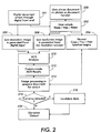
- Fig. 2 is a flow chart of the operation of Fig. 1;
-
- Fig. 1 shows an embodiment, wherein a
document 100 is disposed on a platen (not shown) of ascanner 102, which scanner can be a stand alone one or part of a system, e.g., xerography apparatus. Disposed withinscanner 102 is both an addedlow resolution imager 108, e.g., a digital cameral for imaging the platen, and a normally presenthigh resolution imager 109, e.g. a CCD device, which images only a small portion ofplaten 107 at a time. Signals from bothimagers printer 106, which can be, e.g., a local printer, a network printer, etc. Thisprinter 106 can be an independent printer or be a part of a xerographic or non-xerographic copier, e.g., ink jet, or facsimile (fax) machine. Alternatively, the high resolution signal can be obtained from a remote analog or digital source received atinput port 140. Then the low resolution signal can be obtained by low pass filtering (analog source) or decimating (digital source) the high resolution signal. - The details of
printer 106 are substantially the same as shown in U.S. Patent No. 5,991,201. Animage processor 114 receives signals fromscanner 102 orfront end 140 and generates a color image. Digital signals which represent the blue, green and red density signals of the image are converted in the image processing unit into four bitmaps: yellow (Y), cyan (C), magenta (M), and black (K). The bitmap represents the values of the exposure required for each color component of the pixel.Image processor 114 may contain a low pass filter, a decimator a shading correction unit, an undercolor removal unit (UCR), a masking unit, a dithering unit, a gray level processing unit, and other imaging processing sub-systems known in the art. Theimage processor 114 can store bitmap information for subsequent images or can operate in a real time mode. - At stage A, toner of a first color is formed on either a belt or
drum 116. The photoconductive member is preferably a drum of the type which is typically multilayered and has a substrate, a conductive layer, an optional adhesive layer, an optional hole blocking layer, a charge generating layer and a charge transport layer (none shown). The drum is charged bycharging unit 101. Raster output scanner (ROS) 120, controlled byimage processor unit 114, writes a first color image by selectively erasing charges on thedrum 116. The ROS 120 writes the image information pixel by pixel. It should be noted that either discharged area development (DAD) can be employed in which discharged portions are developed or charged area development (CAD) can be employed in which the charged portions are developed with toner. After the electrostatic latent image has been recorded,drum 116 advances the electrostatic latent image todevelopment station 103. Dry developer material is supplied bydevelopment station 103 to develop the latent image. In the case of CAD development, the charge of the toner particles is opposite in polarity to the charge on the photoconductive surface, thereby attracting toner particles thereto. The latent image is developed with a less than monolayer coverage of toner particles. On the average, the uniformity of the development is such that toner particles are near neighboring toner particles.Development station 103 employs small size toner, preferably having average particles size of about 5 µm. - The developed image is electrostatically transferred to the compliant, low surface energy
intermediate member 110 by applying an electrical bias between thedrum 116 and intermediate member orbelt 110. Any residual toner on thedrum 116 is removed with acleaner 104.Intermediate member 110 may be either a roll or an endless belt with a conductive substrate and a compliant overcoat. The path of the belt is defined by a plurality of internal rollers. An optional plurality ofheating elements 132 are in close proximity to the toned image such that the heat causes the toner particles present on the surface to soften. The softened toner particles pass through a filmlayer formation station 130.Station 130 includes a heated roller (not shown) which is in contact with the softened toner image and a backup pressure roll (not shown) behindintermediate member 110.Filming station 130 spreads the softened toner particles into a thin film so that the small gaps between neighboring toner particles are covered with toner without degradation of the image. The toner flow required is very small to cover the spaces between the toner particles. Ideally, the film forming station should form a film of the desired thickness (about 1 µm) regardless of the local toner coverage. One possible way of achieving this is to make the heated roller self-spaced from theintermediate belt 110 at the desired thickness. One method for achieving this requirement would be to utilize a gravure-type roll for the heated roller not shown). - At stage B illustrated in Fig. 1, formation of a second color takes place in the same manner as described above. The
drum 116 is charged with chargingunit 101, and then it is exposed byROS 120 according to second color image bitmap information. After the electrostatic latent image has been recorded, drum 116 advances the electrostatic latent image todevelopment station 103. Dry developer material with toner of the second color is supplied bydevelopment station 103 to develop the latent image. - The developed image is electrostatically transferred to the
intermediate member 110 by an electrical bias voltage betweendrum 116 andbelt 110. (Any residual toner ondrum 116 is cleaned by cleaner 104). The developed second color image is superimposed on the previous first color image. - Heat from the
optional heater 132 softens the toner particles. The softened toner particles on theintermediate member 110 pass through theheated filming station 116, which spreads the softened image into a thin film without degradation of the image. - The process is repeated for the next two colors at stages C and D. A multi-layer film image is formed by superimposing black, yellow, magenta, and cyan toners. The full color advances to transfusing stage E.
- At transfuse nip 134 illustrated in Fig. 1, the multi-layer full-color film image is transfused to the recording sheet or
paper 126 by the application of heat and pressure between aheated roll 135 behind theintermediate belt 110 and abackup pressure roll 136 behind the recording sheet. Moreover,recording sheet 126 may have a previously transferred toner image present on the back surface thereof as the result of a prior imaging operation, i.e. duplexing. As therecording sheet 126 passes through the transfuse nip 134, the multi-layer toner film adheres to the surface of therecording sheet 126, and due to greater attractive forces between thepaper 126 and toner film, as compared to the attraction between the toner film and the low surface energy surface of the compliantintermediate member 110, the multilayer toner film is transferred to therecording sheet 126 as a full-color image. The transfused image becomes permanent once it advances past the transfuse nip 134 and is allowed to cool below the softening temperature of the toner materials. The cycle for forming another document is initiated following the cleaning of any residual toner from theintermediate belt 110 by cleaner 106. - Normally within the
scanner 102 orimage processor 114 is software performing the operation as shown in Fig. 2. Thefirst step 200 is the user placing thedocument 100 onplaten 107. Other image acquisition methods, e.g., the user placing sheets on a feeder apparatus (not shown), etc., can be used. In particular, as shown bystep 201, a digital document signal enters through a digital front end, e.g.,front end 140. Then the user selects COPY or FAX by clicking on the appropriate icon (not shown) as shown bystep 202. Thelow resolution imager 108 quickly provides signals representative of the entire platen atstep 208. As shown atstep 209, if the document entered through a front end, the low resolution image is quickly generated by decimation (digital signal) or low pass filtering (analog signal). The hardware or software for performing this can be inimager processor 114. Then atstep 210 ACD analysis is done by e.g., as shown said U.S. Patent 5,533,144, hereby incorporated by reference. Any other ACD hardware or software devices and methods can be used. Simultaneous with the above-described steps, and just after step 206, a COPY or FAX function is begun atstep 204 using high resolution data, which is at a slower data rate than the low resolution data rate fromlow resolution imager 108 or from the decimator or low pass filter. This is sent to processstep 214 as is the ACD results as indicated bystep 212.Process step 214 prepares the document for printing after the appropriate image processing has been applied. Appropriate image processing could include scaling, halftoning, color correction, etc. and the results are sent todecision step 216 where it is determined if currency and/or negotiable securities, etc., are detected. If YES, then the video data is invalidated atstep 218, preferably before even partial printing of currency occurs. This causesprinter 106 to not properly print, e.g. to print "INVALID", print in only one color, completely stop printing, etc. If no currency has been detected, then the printer prints document 100 as indicated bystep 220. - It will be appreciated that by adding an inexpensive
low resolution imager 108 toscanner 102, it is possible to quickly perform ACD, thereby preventing even partial printing of currency. This quickness is due to the fact that there is less data from thelow resolution imager 108 than fromhigh resolution imager 109 and also that the ACD software does not require high resolution data.
Claims (10)
- A process comprising:obtaining a high resolution image signal of an object;obtaining a low resolution image signal of said object; andperforming a corrective action if the low resolution signal represents a selected type of image.
- The process of claim 1, wherein said corrective action comprises stopping said high resolution obtaining step.
- An apparatus comprising:a source of a high resolution image signal of an object;a source of a low resolution image signal of said object; anda corrector for performing a corrective action if the low resolution image signal represents a selected type of image signal.
- The apparatus of claim 3, wherein corrective action comprises stopping said high resolution sourcing.
- The apparatus of claim 4, further comprising a printer for printing said high resolution image signal.
- The apparatus of claim 5, wherein said printer comprises xerographic printer.
- The apparatus of claim 5, wherein said corrective action comprises said corrector stopping said printer.
- The apparatus of claim 7, wherein said corrective action stops said printer before even partial printing occurs.
- The apparatus of claim 5, wherein said printer comprises an ink jet printer.
- A xerographic apparatus comprising:a low resolution scanner having a low resolution output image signal of an object;a high resolution scanner having a high resolution output image signal of said object;a corrector performing a corrective action if low resolution output signal represent a selected type of image; anda xerographic printer.
Applications Claiming Priority (2)
| Application Number | Priority Date | Filing Date | Title |
|---|---|---|---|
| US790467 | 2001-02-22 | ||
| US09/790,467 US6470168B1 (en) | 2001-02-22 | 2001-02-22 | ACD using an added low resolution CCD to prevent even partial printout |
Publications (2)
| Publication Number | Publication Date |
|---|---|
| EP1235419A2 true EP1235419A2 (en) | 2002-08-28 |
| EP1235419A3 EP1235419A3 (en) | 2004-01-07 |
Family
ID=25150768
Family Applications (1)
| Application Number | Title | Priority Date | Filing Date |
|---|---|---|---|
| EP02003374A Withdrawn EP1235419A3 (en) | 2001-02-22 | 2002-02-13 | ACD using an added low resolution CCD to prevent even partial printout |
Country Status (4)
| Country | Link |
|---|---|
| US (1) | US6470168B1 (en) |
| EP (1) | EP1235419A3 (en) |
| JP (1) | JP2002335399A (en) |
| CN (1) | CN1207685C (en) |
Cited By (1)
| Publication number | Priority date | Publication date | Assignee | Title |
|---|---|---|---|---|
| EP1725011A1 (en) * | 2005-05-19 | 2006-11-22 | Ricoh Company, Ltd. | Image forming apparatus with copy prohibition function |
Families Citing this family (3)
| Publication number | Priority date | Publication date | Assignee | Title |
|---|---|---|---|---|
| EP1376484A1 (en) * | 2002-06-25 | 2004-01-02 | Mars Incorporated | Method and apparatus for processing signals in testing currency items |
| US20060170951A1 (en) * | 2005-01-31 | 2006-08-03 | Hewlett-Packard Development Company, L.P. | Method and arrangement for inhibiting counterfeit printing of legal tender |
| JP2020155884A (en) * | 2019-03-19 | 2020-09-24 | コニカミノルタ株式会社 | Image formation device, control method of them, and program |
Citations (1)
| Publication number | Priority date | Publication date | Assignee | Title |
|---|---|---|---|---|
| EP0871318A2 (en) | 1997-04-11 | 1998-10-14 | Eastman Kodak Company | Copy restrictive system for color-reversal documents |
Family Cites Families (4)
| Publication number | Priority date | Publication date | Assignee | Title |
|---|---|---|---|---|
| JPH06164914A (en) * | 1992-11-20 | 1994-06-10 | Toppan Printing Co Ltd | Copy protection method and copier |
| EP0664642B1 (en) * | 1994-01-20 | 2002-07-24 | Omron Corporation | Image processing device for identifying an input image, and copier including same |
| US5533144A (en) | 1994-10-17 | 1996-07-02 | Xerox Corporation | Anti-counterfeit pattern detector and method |
| US6011857A (en) * | 1997-08-07 | 2000-01-04 | Eastman Kodak Company | Detecting copy restrictive documents |
-
2001
- 2001-02-22 US US09/790,467 patent/US6470168B1/en not_active Expired - Fee Related
-
2002
- 2002-02-08 JP JP2002031619A patent/JP2002335399A/en active Pending
- 2002-02-13 EP EP02003374A patent/EP1235419A3/en not_active Withdrawn
- 2002-02-22 CN CNB021051860A patent/CN1207685C/en not_active Expired - Fee Related
Patent Citations (1)
| Publication number | Priority date | Publication date | Assignee | Title |
|---|---|---|---|---|
| EP0871318A2 (en) | 1997-04-11 | 1998-10-14 | Eastman Kodak Company | Copy restrictive system for color-reversal documents |
Cited By (1)
| Publication number | Priority date | Publication date | Assignee | Title |
|---|---|---|---|---|
| EP1725011A1 (en) * | 2005-05-19 | 2006-11-22 | Ricoh Company, Ltd. | Image forming apparatus with copy prohibition function |
Also Published As
| Publication number | Publication date |
|---|---|
| US6470168B1 (en) | 2002-10-22 |
| JP2002335399A (en) | 2002-11-22 |
| CN1372223A (en) | 2002-10-02 |
| EP1235419A3 (en) | 2004-01-07 |
| CN1207685C (en) | 2005-06-22 |
Similar Documents
| Publication | Publication Date | Title |
|---|---|---|
| JP3907155B2 (en) | Image data correction apparatus, image reading apparatus, and image forming apparatus | |
| US7016621B1 (en) | Back-transfer reduction in a tandem electrostatographic printer | |
| JPH1055084A (en) | Device for forming toner image of highlight | |
| JP2008532065A (en) | Electrostatic image printing with enhanced color gamut | |
| US6203953B1 (en) | Method for forming a toner image with low toner pile height | |
| US5999201A (en) | Apparatus and method for forming a toner image with low toner pile height | |
| US6456394B1 (en) | Method for reducing halo print defects associated with color images | |
| US6470168B1 (en) | ACD using an added low resolution CCD to prevent even partial printout | |
| EP1008953B1 (en) | Image forming apparatus | |
| US6868174B2 (en) | Anti-counterfeit detection for low end products | |
| US20020064303A1 (en) | Anti-counterfeit detection for low end products | |
| JP2006325026A (en) | Image forming apparatus, image forming method, and image forming program | |
| JP4798854B2 (en) | Image forming apparatus and residual toner removing method in image forming apparatus | |
| JP6060764B2 (en) | Image processing apparatus and image forming apparatus | |
| US8345312B2 (en) | Method of printing a text with an apparatus using channels | |
| JP3906964B2 (en) | Image processing apparatus and image forming apparatus | |
| US5867635A (en) | Selectable quality control and productivity in a color reprographic printing machine | |
| JP3958923B2 (en) | Image data processing apparatus, image reading apparatus, and image forming apparatus | |
| JP3363356B2 (en) | Color image forming equipment | |
| JP2003162182A (en) | Image forming device | |
| JP3402963B2 (en) | Image forming device | |
| JP3659403B2 (en) | Image processing device | |
| JP2003324602A (en) | Image forming device | |
| JP2002112033A (en) | Image reading processing method, image reading apparatus, and image forming apparatus | |
| JPH05181344A (en) | Color image forming apparatus and method thereof |
Legal Events
| Date | Code | Title | Description |
|---|---|---|---|
| PUAI | Public reference made under article 153(3) epc to a published international application that has entered the european phase |
Free format text: ORIGINAL CODE: 0009012 |
|
| AK | Designated contracting states |
Kind code of ref document: A2 Designated state(s): AT BE CH CY DE DK ES FI FR GB GR IE IT LI LU MC NL PT SE TR |
|
| AX | Request for extension of the european patent |
Free format text: AL;LT;LV;MK;RO;SI |
|
| PUAL | Search report despatched |
Free format text: ORIGINAL CODE: 0009013 |
|
| AK | Designated contracting states |
Kind code of ref document: A3 Designated state(s): AT BE CH CY DE DK ES FI FR GB GR IE IT LI LU MC NL PT SE TR |
|
| AX | Request for extension of the european patent |
Extension state: AL LT LV MK RO SI |
|
| RIC1 | Information provided on ipc code assigned before grant |
Ipc: 7G 07D 7/20 B Ipc: 7H 04N 1/00 A |
|
| RTI1 | Title (correction) |
Free format text: ACD USING AN ADDED LOW RESOLUTION CCD TO PREVENT EVEN PARTIAL PRINTOUT |
|
| 17P | Request for examination filed |
Effective date: 20040707 |
|
| AKX | Designation fees paid |
Designated state(s): DE FR GB |
|
| 17Q | First examination report despatched |
Effective date: 20090205 |
|
| STAA | Information on the status of an ep patent application or granted ep patent |
Free format text: STATUS: THE APPLICATION IS DEEMED TO BE WITHDRAWN |
|
| 18D | Application deemed to be withdrawn |
Effective date: 20140902 |