EP1235243A1 - Disjoncteur incluant un canal de vidange de la chambre de compression par piston - Google Patents
Disjoncteur incluant un canal de vidange de la chambre de compression par piston Download PDFInfo
- Publication number
- EP1235243A1 EP1235243A1 EP02290175A EP02290175A EP1235243A1 EP 1235243 A1 EP1235243 A1 EP 1235243A1 EP 02290175 A EP02290175 A EP 02290175A EP 02290175 A EP02290175 A EP 02290175A EP 1235243 A1 EP1235243 A1 EP 1235243A1
- Authority
- EP
- European Patent Office
- Prior art keywords
- chamber
- circuit breaker
- thermal
- compression chamber
- piston
- Prior art date
- Legal status (The legal status is an assumption and is not a legal conclusion. Google has not performed a legal analysis and makes no representation as to the accuracy of the status listed.)
- Granted
Links
- 230000006835 compression Effects 0.000 title claims abstract description 56
- 238000007906 compression Methods 0.000 title claims abstract description 56
- 239000007789 gas Substances 0.000 claims description 45
- 238000007664 blowing Methods 0.000 claims description 38
- 238000010891 electric arc Methods 0.000 claims description 10
- 230000001105 regulatory effect Effects 0.000 abstract 1
- 238000006073 displacement reaction Methods 0.000 description 2
- 238000010438 heat treatment Methods 0.000 description 2
- 206010061876 Obstruction Diseases 0.000 description 1
- 238000010276 construction Methods 0.000 description 1
- 239000012777 electrically insulating material Substances 0.000 description 1
- 238000002347 injection Methods 0.000 description 1
- 239000007924 injection Substances 0.000 description 1
- 230000002093 peripheral effect Effects 0.000 description 1
- 230000008929 regeneration Effects 0.000 description 1
- 238000011069 regeneration method Methods 0.000 description 1
- 238000011144 upstream manufacturing Methods 0.000 description 1
Images
Classifications
-
- H—ELECTRICITY
- H01—ELECTRIC ELEMENTS
- H01H—ELECTRIC SWITCHES; RELAYS; SELECTORS; EMERGENCY PROTECTIVE DEVICES
- H01H33/00—High-tension or heavy-current switches with arc-extinguishing or arc-preventing means
- H01H33/70—Switches with separate means for directing, obtaining, or increasing flow of arc-extinguishing fluid
- H01H33/88—Switches with separate means for directing, obtaining, or increasing flow of arc-extinguishing fluid the flow of arc-extinguishing fluid being produced or increased by movement of pistons or other pressure-producing parts
- H01H33/90—Switches with separate means for directing, obtaining, or increasing flow of arc-extinguishing fluid the flow of arc-extinguishing fluid being produced or increased by movement of pistons or other pressure-producing parts this movement being effected by or in conjunction with the contact-operating mechanism
- H01H33/901—Switches with separate means for directing, obtaining, or increasing flow of arc-extinguishing fluid the flow of arc-extinguishing fluid being produced or increased by movement of pistons or other pressure-producing parts this movement being effected by or in conjunction with the contact-operating mechanism making use of the energy of the arc or an auxiliary arc
Definitions
- the invention relates to a circuit breaker comprising two contacts arranged in a breaking space filled with a dielectric gas under pressure and between which an electric arc is established during an operation opening of the circuit breaker, and including a blowing chamber thermal communicating directly with the breaking space and a compression chamber by piston communicating with the thermal blowing, and in which the compression chamber by piston communicates with the cutting space through an evacuation channel which is separated from the thermal blowing chamber and which is closed by a valve.
- Such a high voltage circuit breaker is known from the German patent DE-19613030.
- the breaking space is delimited by the neck and the diverging part of a nozzle secured to the movable contact of the circuit breaker.
- the fixed contact of the circuit breaker crosses the neck of the nozzle.
- the thermal blowing chamber and the discharge channel open directly into the nozzle neck and the valve is mounted between the piston compression chamber and the exhaust channel so as to prevent a return of gases from the cutting space towards the piston compression chamber.
- the canal is connected to the neck of the nozzle so that during a circuit breaker opening operation, the thermal blowing chamber is put in communication with the breaking space before setting communication of the piston compression chamber with the breaking chamber through the discharge channel.
- the dielectric gas When a low current is cut off, the dielectric gas is put faster overpressure in the compression chamber by piston than in the thermal blowing chamber. Due to the difference of gas overpressure between these two chambers, the one-way valve, placed in the communication channel between the two chambers, opens and the gas overpressure in the piston compression chamber is blown into the cutting space through the blowing chamber thermal. But part of the gas in overpressure in the chamber piston compression is also discharged into the cut-out space through the drainage channel. This gas escape through the channel evacuation to reduce the intrinsic extinguishing capacity by blowing the compression chamber by piston.
- the object of the invention is to provide a circuit breaker which does not have not the disadvantages indicated above.
- a goal of the invention is to provide a circuit breaker in which, when breaking of a weak current, all the gas in overpressure in the chamber of compression by piston passing through the thermal blowing chamber to blow the electric arc which is established between the two contacts of the circuit breaker and, in which, when a strong current is cut, the piston compression chamber is drained completely without use of calibrated valves in the compression piston but by gas evacuation in the breaking space through a channel separate evacuation, this injection of little or no ionized gas contributing to regenerate the hot gases present in the breaking space to improve the dielectric strength of the circuit breaker during an operation subsequent opening of it.
- the invention relates to a circuit breaker comprising two contacts arranged in a breaking space filled with a gas dielectric under pressure and between which an electric arc is established during an operation to open the circuit breaker, and including a thermal blowing communicating directly with the space of cut-off and a piston compression chamber communicating with the compression chamber, and in which the compression chamber by piston communicates with the cutting space through a channel separate discharge from the thermal blowing chamber and closed by a valve, characterized in that said valve is disposed between the chamber of thermal blowing and the compression chamber by piston of such so as to open to allow the evacuation of overpressure gases from the piston compression chamber to the cutting space through said channel when the gas overpressure in the blowing chamber thermal is higher than the gas overpressure in the piston compression.
- the valve is displaced by the resulting force corresponding to the gap between the gas overpressure in the thermal blowing chamber and the gas overpressure in the piston compression chamber.
- the overpressure in the compression by piston is more important than in the chamber of thermal blowing and the resulting force acting on the valve tends to keep in its closed position to prevent emptying of the piston compression chamber through the discharge channel.
- the gases in the piston compression chamber are therefore blown into the cut-off space through the one-way valve and the thermal blowing.
- breaking a strong current the force resulting which acts on the valve tends on the contrary to move it to open the evacuation channel which allows the emptying of the compression by piston in the cutting space.
- the valve is a movable ring through the bottom of the thermal blowing chamber and the ceiling of the chamber compression piston and the discharge channel has an opening which opens into the ceiling of the piston compression chamber.
- the crown is pressed against the opening of the drainage channel under the action of a return spring working between the crown and the bottom of the thermal blowing chamber.
- the cutting space is defined by a nozzle having a neck and a diverging and the evacuation channel opens into the diverging downstream of the nozzle neck.
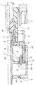
- circuit breaker according to the invention is described below in detail and illustrated schematically in the single figure.
- the figure shows schematically, in axial half-section, a exemplary embodiment of a high voltage circuit breaker according to the invention.
- the circuit breaker comprises a fixed arcing contact 1 in the form of a rod and a movable arcing contact 2 which is displaced in the axial direction A.
- the contact 2 is hollow and is part of a moving assembly including a nozzle blowing 3 coaxial with contacts 1 and 2, a blowing chamber thermal 4 and a piston compression chamber 5.
- the crew mobile also includes a permanent current contact 6 which cooperates when the circuit breaker closes with a permanent current contact 7 which is fixed.
- the nozzle 3 made of an electrically insulating material, comprises a diverging 3B downstream of the neck 3A of narrowed section.
- the arcing contact 1 crosses the neck 3B of the nozzle and enters the hollow contact 2 disposed upstream of the neck 3A of the nozzle according to the direction of travel for closing contact 2.
- the neck 3A and the diverging 3B of the nozzle define the space of interruption of an electric arc that stretches between the two contacts 1 and 2 during a circuit breaker opening operation.
- This breaking space is filled with a dielectric insulating gas, such as SF6, under pressure a few bars, for example 3 bars.
- This breaking space communicates with the blowing chamber thermal 4 via an annular channel 8 formed in the nozzle 3 and which opens on the side of the cutting space in the neck 3A of the nozzle.
- the thermal blowing chamber 4 defines a fixed volume annular coaxial with contacts 1 and 2 in which the dielectric gas is overpressure by heating in contact with the electric arc which is established between contacts 1 and 2 on opening.
- the piston compression chamber 5 is adjacent to the chamber 4 and defines a variable annular volume also coaxial with contacts 1 and 2 in which the dielectric gas is put under overpressure by displacement of a piston 9 constituting the bottom 5A of the chamber 5.
- the ceiling 5B of the chamber 5 is merged with the bottom 4A of the chamber 4 and the channel 8 opens into the ceiling 4B of room 4.
- the thermal blowing chamber 4 communicates with the compression chamber by piston 5 through a channel 10 passing through the bottom 4A and the floor 5B.
- Channel 10 is closed by a valve unidirectional 11 allowing only gas flow from the chamber 5 towards chamber 4.
- the bottom 5A of the compression chamber by piston also constituting piston 9 is also crossed by a channel closed by a one-way valve 12 letting the gas pass from the rear of the piston to chamber 5 when the breaker.
- the piston compression chamber 5 communicates with the breaking space through an annular channel 13 coaxial with contacts 1 and 2 and which leads, on the one hand, into the diverging 3B from the nozzle and, on the other hand, in the ceiling 5B from the compression chamber by piston 5.
- a valve 14 is also disposed between the thermal blowing chamber 4 and the compression by piston 5. It crosses the ceiling 5B or the bottom 4A and opens from the side of the compression chamber by piston 5.
- This valve 14 here is in the form of a movable crown mounted according to the direction A as indicated by the arrow.
- the crown 14 has a peripheral annular stop 15 which extends radially under the opening of channel 13 opening into chamber 5.
- An annular spring 16 works between the bottom 4A of the thermal blowing chamber 4 and the crown 14 to close the channel 13 while maintaining the stop 15 against the opening of the channel 13 opening into the chamber 5.
- a displacement from the crown 14 to the left of the figure and therefore in the chamber 5 opens the channel 13 while a movement of the crown 14 towards the right of the figure and therefore in the chamber 4 tends to close the channel 13.
- the volume of gas in the chamber 5 rises faster in overpressure than the volume of gas in chamber 4 and the unidirectional valve 11 opens the channel 10 connecting rooms 4 and 5.
- the overpressure in the chamber 5 being greater than the overpressure in chamber 4, the force resulting tends to move the crown 14 to the right of the figure and is added to that exerted by the spring 16 so that the stop 15 of the crown closes the discharge channel 13.
- all the gas overpressure in chamber 5 is blown into the breaking space on the root of the electric arc through channel 10, chamber 4 and channel 8.
- the discharge channel 13 is always closed by the crown 14 which prevents the return of hot gases from the breaking space to the room 5.
- the discharge channel 13 has a part of length which extends parallel to direction A in the thickness of the outer wall of the thermal blowing chamber 4. Thus, the discharge channel 13 does not pass through the defined volume of gas through the thermal blowing chamber.
Landscapes
- Circuit Breakers (AREA)
- Switches Operated By Changes In Physical Conditions (AREA)
- Percussive Tools And Related Accessories (AREA)
Abstract
Description
Claims (4)
- Disjoncteur comprenant deux contacts (1,2) disposés dans un espace de coupure rempli d'un gaz diélectrique sous pression et entre lesquels s'établit un arc électrique lors d'une opération d'ouverture du disjoncteur, et incluant une chambre de soufflage thermique (4) communiquant directement avec l'espace de coupure et une chambre de compression par piston (5) communiquant avec la chambre de soufflage thermique (4), et dans lequel la chambre de compression par piston (5) communique avec l'espace de coupure par un canal d'évacuation (13) séparé de la chambre de soufflage thermique et fermé par un clapet (14), caractérisé en ce que ledit clapet (14) est disposé entre la chambre de soufflage thermique (4) et la chambre de compression par piston (5) de telle manière à s'ouvrir pour permettre l'évacuation du gaz en surpression de la chambre de compression par piston (5) vers l'espace de coupure à travers ledit canal (13) quand la surpression des gaz dans la chambre de soufflage thermique est supérieure à la surpression des gaz dans la chambre de compression par piston.
- Disjoncteur selon la revendication 1, dans lequel le clapet (14) est une couronne mobile traversant le fond (4A) de la chambre de soufflage thermique et le plafond (5B) de la chambre de compression par piston, dans lequel le canal d'évacuation (13) a une ouverture qui débouche dans le plafond (5B) de la chambre de compression par piston et dans lequel ladite couronne est plaquée contre l'ouverture du canal d'évacuation sous l'action d'un ressort de rappel (16) travaillant entre la couronne et le fond de la chambre de soufflage thermique.
- Disjoncteur selon l'une des revendications 1 à 2, dans lequel l'espace de coupure est défini par une buse (3) ayant un divergeant (3B) dans lequel débouche le canal d'évacuation (13).
- Disjoncteur selon l'une des revendications 1 à 3, dans lequel le canal d'évacuation (13) est formé dans une paroi de la chambre de soufflage thermique (4).
Applications Claiming Priority (2)
| Application Number | Priority Date | Filing Date | Title |
|---|---|---|---|
| FR0102627A FR2821482B1 (fr) | 2001-02-27 | 2001-02-27 | Disjoncteur incluant un canal de vidange de la chambre de compression par piston |
| FR0102627 | 2001-02-27 |
Publications (2)
| Publication Number | Publication Date |
|---|---|
| EP1235243A1 true EP1235243A1 (fr) | 2002-08-28 |
| EP1235243B1 EP1235243B1 (fr) | 2010-04-28 |
Family
ID=8860478
Family Applications (1)
| Application Number | Title | Priority Date | Filing Date |
|---|---|---|---|
| EP02290175A Expired - Lifetime EP1235243B1 (fr) | 2001-02-27 | 2002-01-24 | Disjoncteur incluant un canal de vidange de la chambre de compression par piston |
Country Status (5)
| Country | Link |
|---|---|
| US (1) | US6624371B2 (fr) |
| EP (1) | EP1235243B1 (fr) |
| AT (1) | ATE466372T1 (fr) |
| DE (1) | DE60236122D1 (fr) |
| FR (1) | FR2821482B1 (fr) |
Cited By (1)
| Publication number | Priority date | Publication date | Assignee | Title |
|---|---|---|---|---|
| EP1863054A1 (fr) * | 2006-05-29 | 2007-12-05 | ABB Technology AG | Interrupteur à piston de soufflage avec un clapet de surpression |
Families Citing this family (9)
| Publication number | Priority date | Publication date | Assignee | Title |
|---|---|---|---|---|
| ATE433191T1 (de) * | 2006-04-05 | 2009-06-15 | Abb Research Ltd | Schaltkammer eines hochspannungsschalters mit einem heizvolumen veränderbarer grösse |
| US20070241079A1 (en) * | 2006-04-13 | 2007-10-18 | Johnson David S | High voltage circuit breaker with re-fill valve |
| FR2937179A1 (fr) | 2008-10-09 | 2010-04-16 | Areva T & D Sa | Chambre de coupure pour disjoncteur haute tension a soufflage d'arc ameliore |
| FR2947377B1 (fr) | 2009-06-29 | 2011-07-22 | Areva T & D Sa | Valve a clapet de decharge destinee a decharger un gaz dielectrique entre deux volumes d'une chambre de coupure de disjoncteur haute ou moyenne tension |
| JP5389279B2 (ja) * | 2011-01-07 | 2014-01-15 | 三菱電機株式会社 | 開閉装置 |
| HUE050927T2 (hu) * | 2017-06-20 | 2021-01-28 | General Electric Technology Gmbh | Elektromos nagyfeszültségû megszakító |
| DE102018211621A1 (de) * | 2018-07-12 | 2020-01-16 | Siemens Aktiengesellschaft | Gasisolierter Schalter |
| CN113330529B (zh) * | 2019-03-19 | 2024-04-02 | 株式会社东芝 | 气体断路器 |
| JP2024124633A (ja) * | 2023-03-03 | 2024-09-13 | 株式会社東芝 | ガス遮断器 |
Citations (5)
| Publication number | Priority date | Publication date | Assignee | Title |
|---|---|---|---|---|
| DE1127442B (de) * | 1959-06-10 | 1962-04-12 | Siemens Ag | Elektrischer Fluessigkeitsschalter |
| US4046979A (en) * | 1974-11-25 | 1977-09-06 | Siemens Aktiengesellschaft | Arc quenching arrangement for a gas-flow type circuit breaker |
| DE29520809U1 (de) * | 1995-12-19 | 1996-02-15 | Siemens AG, 80333 München | Hochspannungs-Leistungsschalter mit einem Gasspeicherraum |
| WO1996021234A1 (fr) * | 1994-12-29 | 1996-07-11 | Asea Brown Boveri Ab | Disjoncteur a haute tension |
| DE19613030A1 (de) * | 1996-03-19 | 1997-09-25 | Siemens Ag | Elektrischer Hochspannungs-Leistungsschalter mit einem Heizraum |
Family Cites Families (2)
| Publication number | Priority date | Publication date | Assignee | Title |
|---|---|---|---|---|
| CH568649A5 (fr) * | 1974-07-29 | 1975-10-31 | Sprecher & Schuh Ag | |
| FR2720188B1 (fr) * | 1994-05-19 | 1996-06-14 | Gec Alsthom T & D Sa | Disjoncteur à autocompression réduite. |
-
2001
- 2001-02-27 FR FR0102627A patent/FR2821482B1/fr not_active Expired - Fee Related
-
2002
- 2002-01-24 DE DE60236122T patent/DE60236122D1/de not_active Expired - Lifetime
- 2002-01-24 EP EP02290175A patent/EP1235243B1/fr not_active Expired - Lifetime
- 2002-01-24 AT AT02290175T patent/ATE466372T1/de not_active IP Right Cessation
- 2002-01-31 US US10/059,360 patent/US6624371B2/en not_active Expired - Fee Related
Patent Citations (6)
| Publication number | Priority date | Publication date | Assignee | Title |
|---|---|---|---|---|
| DE1127442B (de) * | 1959-06-10 | 1962-04-12 | Siemens Ag | Elektrischer Fluessigkeitsschalter |
| US4046979A (en) * | 1974-11-25 | 1977-09-06 | Siemens Aktiengesellschaft | Arc quenching arrangement for a gas-flow type circuit breaker |
| WO1996021234A1 (fr) * | 1994-12-29 | 1996-07-11 | Asea Brown Boveri Ab | Disjoncteur a haute tension |
| EP0806049A1 (fr) * | 1994-12-29 | 1997-11-12 | Asea Brown Boveri Ab | Disjoncteur a haute tension |
| DE29520809U1 (de) * | 1995-12-19 | 1996-02-15 | Siemens AG, 80333 München | Hochspannungs-Leistungsschalter mit einem Gasspeicherraum |
| DE19613030A1 (de) * | 1996-03-19 | 1997-09-25 | Siemens Ag | Elektrischer Hochspannungs-Leistungsschalter mit einem Heizraum |
Cited By (2)
| Publication number | Priority date | Publication date | Assignee | Title |
|---|---|---|---|---|
| EP1863054A1 (fr) * | 2006-05-29 | 2007-12-05 | ABB Technology AG | Interrupteur à piston de soufflage avec un clapet de surpression |
| US7820933B2 (en) | 2006-05-29 | 2010-10-26 | Abb Technology Ag | Puffer circuit breaker with an overpressure valve |
Also Published As
| Publication number | Publication date |
|---|---|
| ATE466372T1 (de) | 2010-05-15 |
| FR2821482B1 (fr) | 2003-04-04 |
| US20020117475A1 (en) | 2002-08-29 |
| EP1235243B1 (fr) | 2010-04-28 |
| US6624371B2 (en) | 2003-09-23 |
| DE60236122D1 (de) | 2010-06-10 |
| FR2821482A1 (fr) | 2002-08-30 |
Similar Documents
| Publication | Publication Date | Title |
|---|---|---|
| EP2332160B1 (fr) | Chambre de coupure pour disjoncteur haute tension à soufflage d'arc ameliore | |
| EP0239068B1 (fr) | Disjoncteur à gaz diélectrique sous pression | |
| FR2632771A1 (fr) | Disjoncteur limiteur basse tension a chambre de coupure etanche | |
| EP1235243B1 (fr) | Disjoncteur incluant un canal de vidange de la chambre de compression par piston | |
| EP0179834B1 (fr) | Dispositif interrupteur a ecran de coupure d'arc | |
| FR2576142A1 (fr) | Disjoncteur a haute tension, a gaz comprime, a energie de manoeuvre assistee par l'effet thermique de l'arc | |
| EP0367072B1 (fr) | Disjoncteur à haute tension à gaz diélectrique sous pression | |
| EP0821382A1 (fr) | Disjoncteur à haute tension à autosoufflage d'arc | |
| FR2696274A1 (fr) | Disjoncteur à haute tension à auto-soufflage ayant une chambre de coupure à compression de gaz réduite. | |
| FR2576144A1 (fr) | Disjoncteur a haute tension, a gaz comprime, a faible energie de manoeuvre | |
| FR2610763A1 (fr) | Disjoncteur a faible energie de manoeuvre | |
| FR2766609A1 (fr) | Interrupteur a gaz a volume d'expansion thermique compressible | |
| EP1148528B1 (fr) | Interrupteur à auto-soufflage avec une chambre de coupure à deux volumes | |
| EP0458236B1 (fr) | Disjoncteur à moyenne tension | |
| CA2101214C (fr) | Disjoncteur a deux chambres de coupure concentriques | |
| FR2535518A1 (fr) | Chambre de coupure pour disjoncteur a gaz | |
| EP0986081A1 (fr) | Interrupteur avec un système d'insertion d'une résistance à longue durée d'insertion | |
| FR2980033A1 (fr) | Chambre de coupure pour disjoncteur | |
| FR2575594A1 (fr) | Disjoncteur a gaz dielectrique sous pression a auto-soufflage | |
| FR2563372A1 (fr) | Disjoncteur haute tension a soufflage d'arc | |
| FR2509521A1 (fr) | Disjoncteur a haute tension sous enveloppe contenant un gaz isolant | |
| CH688702A5 (fr) | Disjoncteur à haute tension ayant une chambre de coupure à volume de soufflage variable. | |
| CA1251818A (fr) | Disjoncteur haute tension a soufflage d'arc | |
| FR2762925A1 (fr) | Disjoncteur a haute tension a double mouvement des contacts d'arc | |
| FR2751462A1 (fr) | Disjoncteur a haute tension a auto-soufflage d'arc |
Legal Events
| Date | Code | Title | Description |
|---|---|---|---|
| PUAI | Public reference made under article 153(3) epc to a published international application that has entered the european phase |
Free format text: ORIGINAL CODE: 0009012 |
|
| AK | Designated contracting states |
Kind code of ref document: A1 Designated state(s): AT BE CH CY DE DK ES FI FR GB GR IE IT LI LU MC NL PT SE TR |
|
| AX | Request for extension of the european patent |
Free format text: AL;LT;LV;MK;RO;SI |
|
| 17P | Request for examination filed |
Effective date: 20030228 |
|
| AKX | Designation fees paid |
Designated state(s): AT BE CH CY DE DK ES FI FR GB GR IE IT LI LU MC NL PT SE TR |
|
| RAP1 | Party data changed (applicant data changed or rights of an application transferred) |
Owner name: AREVA T&D SA |
|
| RAP1 | Party data changed (applicant data changed or rights of an application transferred) |
Owner name: AREVA T&D SA |
|
| 17Q | First examination report despatched |
Effective date: 20090904 |
|
| RAP1 | Party data changed (applicant data changed or rights of an application transferred) |
Owner name: AREVA T&D SAS |
|
| RAP1 | Party data changed (applicant data changed or rights of an application transferred) |
Owner name: AREVA T&D SAS |
|
| GRAP | Despatch of communication of intention to grant a patent |
Free format text: ORIGINAL CODE: EPIDOSNIGR1 |
|
| GRAS | Grant fee paid |
Free format text: ORIGINAL CODE: EPIDOSNIGR3 |
|
| GRAA | (expected) grant |
Free format text: ORIGINAL CODE: 0009210 |
|
| AK | Designated contracting states |
Kind code of ref document: B1 Designated state(s): AT BE CH CY DE DK ES FI FR GB GR IE IT LI LU MC NL PT SE TR |
|
| REG | Reference to a national code |
Ref country code: GB Ref legal event code: FG4D Free format text: NOT ENGLISH |
|
| REG | Reference to a national code |
Ref country code: CH Ref legal event code: EP |
|
| REG | Reference to a national code |
Ref country code: IE Ref legal event code: FG4D Free format text: LANGUAGE OF EP DOCUMENT: FRENCH |
|
| REF | Corresponds to: |
Ref document number: 60236122 Country of ref document: DE Date of ref document: 20100610 Kind code of ref document: P |
|
| REG | Reference to a national code |
Ref country code: SE Ref legal event code: TRGR |
|
| REG | Reference to a national code |
Ref country code: NL Ref legal event code: VDEP Effective date: 20100428 |
|
| PG25 | Lapsed in a contracting state [announced via postgrant information from national office to epo] |
Ref country code: ES Free format text: LAPSE BECAUSE OF FAILURE TO SUBMIT A TRANSLATION OF THE DESCRIPTION OR TO PAY THE FEE WITHIN THE PRESCRIBED TIME-LIMIT Effective date: 20100808 Ref country code: NL Free format text: LAPSE BECAUSE OF FAILURE TO SUBMIT A TRANSLATION OF THE DESCRIPTION OR TO PAY THE FEE WITHIN THE PRESCRIBED TIME-LIMIT Effective date: 20100428 |
|
| REG | Reference to a national code |
Ref country code: IE Ref legal event code: FD4D |
|
| PG25 | Lapsed in a contracting state [announced via postgrant information from national office to epo] |
Ref country code: AT Free format text: LAPSE BECAUSE OF FAILURE TO SUBMIT A TRANSLATION OF THE DESCRIPTION OR TO PAY THE FEE WITHIN THE PRESCRIBED TIME-LIMIT Effective date: 20100428 Ref country code: FI Free format text: LAPSE BECAUSE OF FAILURE TO SUBMIT A TRANSLATION OF THE DESCRIPTION OR TO PAY THE FEE WITHIN THE PRESCRIBED TIME-LIMIT Effective date: 20100428 |
|
| PG25 | Lapsed in a contracting state [announced via postgrant information from national office to epo] |
Ref country code: GR Free format text: LAPSE BECAUSE OF FAILURE TO SUBMIT A TRANSLATION OF THE DESCRIPTION OR TO PAY THE FEE WITHIN THE PRESCRIBED TIME-LIMIT Effective date: 20100729 Ref country code: CY Free format text: LAPSE BECAUSE OF FAILURE TO SUBMIT A TRANSLATION OF THE DESCRIPTION OR TO PAY THE FEE WITHIN THE PRESCRIBED TIME-LIMIT Effective date: 20100428 |
|
| PG25 | Lapsed in a contracting state [announced via postgrant information from national office to epo] |
Ref country code: PT Free format text: LAPSE BECAUSE OF FAILURE TO SUBMIT A TRANSLATION OF THE DESCRIPTION OR TO PAY THE FEE WITHIN THE PRESCRIBED TIME-LIMIT Effective date: 20100830 Ref country code: IE Free format text: LAPSE BECAUSE OF FAILURE TO SUBMIT A TRANSLATION OF THE DESCRIPTION OR TO PAY THE FEE WITHIN THE PRESCRIBED TIME-LIMIT Effective date: 20100428 Ref country code: DK Free format text: LAPSE BECAUSE OF FAILURE TO SUBMIT A TRANSLATION OF THE DESCRIPTION OR TO PAY THE FEE WITHIN THE PRESCRIBED TIME-LIMIT Effective date: 20100428 |
|
| PLBE | No opposition filed within time limit |
Free format text: ORIGINAL CODE: 0009261 |
|
| STAA | Information on the status of an ep patent application or granted ep patent |
Free format text: STATUS: NO OPPOSITION FILED WITHIN TIME LIMIT |
|
| 26N | No opposition filed |
Effective date: 20110131 |
|
| BERE | Be: lapsed |
Owner name: AREVA T&D SAS Effective date: 20110131 |
|
| PG25 | Lapsed in a contracting state [announced via postgrant information from national office to epo] |
Ref country code: MC Free format text: LAPSE BECAUSE OF NON-PAYMENT OF DUE FEES Effective date: 20110131 |
|
| GBPC | Gb: european patent ceased through non-payment of renewal fee |
Effective date: 20110124 |
|
| PG25 | Lapsed in a contracting state [announced via postgrant information from national office to epo] |
Ref country code: GB Free format text: LAPSE BECAUSE OF NON-PAYMENT OF DUE FEES Effective date: 20110124 Ref country code: BE Free format text: LAPSE BECAUSE OF NON-PAYMENT OF DUE FEES Effective date: 20110131 |
|
| REG | Reference to a national code |
Ref country code: FR Ref legal event code: CA Effective date: 20121204 Ref country code: FR Ref legal event code: CD Owner name: ALSTOM GRID SAS, FR Effective date: 20121204 |
|
| REG | Reference to a national code |
Ref country code: DE Ref legal event code: R081 Ref document number: 60236122 Country of ref document: DE Owner name: ALSTOM GRID SAS, FR Free format text: FORMER OWNER: AREVA T&D SAS, PARIS, FR Effective date: 20130225 Ref country code: DE Ref legal event code: R082 Ref document number: 60236122 Country of ref document: DE Representative=s name: ZEITLER VOLPERT KANDLBINDER, DE Effective date: 20130225 Ref country code: DE Ref legal event code: R081 Ref document number: 60236122 Country of ref document: DE Owner name: ALSTOM TECHNOLOGY LTD., CH Free format text: FORMER OWNER: AREVA T&D SAS, PARIS, FR Effective date: 20130225 Ref country code: DE Ref legal event code: R082 Ref document number: 60236122 Country of ref document: DE Representative=s name: ZEITLER VOLPERT KANDLBINDER PATENTANWAELTE PAR, DE Effective date: 20130225 Ref country code: DE Ref legal event code: R082 Ref document number: 60236122 Country of ref document: DE Representative=s name: ZEITLER VOLPERT KANDLBINDER PATENT- UND RECHTS, DE Effective date: 20130225 |
|
| PG25 | Lapsed in a contracting state [announced via postgrant information from national office to epo] |
Ref country code: LU Free format text: LAPSE BECAUSE OF NON-PAYMENT OF DUE FEES Effective date: 20110124 |
|
| REG | Reference to a national code |
Ref country code: DE Ref legal event code: R082 Ref document number: 60236122 Country of ref document: DE Representative=s name: ZEITLER VOLPERT KANDLBINDER, DE |
|
| REG | Reference to a national code |
Ref country code: DE Ref legal event code: R082 Ref document number: 60236122 Country of ref document: DE Representative=s name: ZEITLER VOLPERT KANDLBINDER, DE Effective date: 20130618 Ref country code: DE Ref legal event code: R081 Ref document number: 60236122 Country of ref document: DE Owner name: ALSTOM TECHNOLOGY LTD., CH Free format text: FORMER OWNER: ALSTOM GRID SAS, PARIS, FR Effective date: 20130618 Ref country code: DE Ref legal event code: R082 Ref document number: 60236122 Country of ref document: DE Representative=s name: ZEITLER VOLPERT KANDLBINDER PATENTANWAELTE PAR, DE Effective date: 20130618 Ref country code: DE Ref legal event code: R082 Ref document number: 60236122 Country of ref document: DE Representative=s name: ZEITLER VOLPERT KANDLBINDER PATENT- UND RECHTS, DE Effective date: 20130618 |
|
| REG | Reference to a national code |
Ref country code: FR Ref legal event code: TP Owner name: ALSTOM TECHNOLOGY LTD, CH Effective date: 20130710 |
|
| REG | Reference to a national code |
Ref country code: CH Ref legal event code: PUE Owner name: ALSTOM TECHNOLOGY LTD, CH Free format text: FORMER OWNER: AREVA T&D SAS, FR |
|
| PG25 | Lapsed in a contracting state [announced via postgrant information from national office to epo] |
Ref country code: TR Free format text: LAPSE BECAUSE OF FAILURE TO SUBMIT A TRANSLATION OF THE DESCRIPTION OR TO PAY THE FEE WITHIN THE PRESCRIBED TIME-LIMIT Effective date: 20100428 |
|
| PGFP | Annual fee paid to national office [announced via postgrant information from national office to epo] |
Ref country code: DE Payment date: 20140107 Year of fee payment: 13 Ref country code: SE Payment date: 20140110 Year of fee payment: 13 Ref country code: CH Payment date: 20140110 Year of fee payment: 13 |
|
| PGFP | Annual fee paid to national office [announced via postgrant information from national office to epo] |
Ref country code: IT Payment date: 20140115 Year of fee payment: 13 Ref country code: FR Payment date: 20140131 Year of fee payment: 13 |
|
| REG | Reference to a national code |
Ref country code: DE Ref legal event code: R119 Ref document number: 60236122 Country of ref document: DE |
|
| REG | Reference to a national code |
Ref country code: CH Ref legal event code: PL |
|
| REG | Reference to a national code |
Ref country code: SE Ref legal event code: EUG |
|
| PG25 | Lapsed in a contracting state [announced via postgrant information from national office to epo] |
Ref country code: LI Free format text: LAPSE BECAUSE OF NON-PAYMENT OF DUE FEES Effective date: 20150131 Ref country code: CH Free format text: LAPSE BECAUSE OF NON-PAYMENT OF DUE FEES Effective date: 20150131 Ref country code: DE Free format text: LAPSE BECAUSE OF NON-PAYMENT OF DUE FEES Effective date: 20150801 |
|
| REG | Reference to a national code |
Ref country code: FR Ref legal event code: ST Effective date: 20150930 |
|
| PG25 | Lapsed in a contracting state [announced via postgrant information from national office to epo] |
Ref country code: FR Free format text: LAPSE BECAUSE OF NON-PAYMENT OF DUE FEES Effective date: 20150202 Ref country code: SE Free format text: LAPSE BECAUSE OF NON-PAYMENT OF DUE FEES Effective date: 20150125 |
|
| PG25 | Lapsed in a contracting state [announced via postgrant information from national office to epo] |
Ref country code: IT Free format text: LAPSE BECAUSE OF NON-PAYMENT OF DUE FEES Effective date: 20150124 |