EP1235078A2 - Method for detecting radar system failures and radar system - Google Patents
Method for detecting radar system failures and radar system Download PDFInfo
- Publication number
- EP1235078A2 EP1235078A2 EP01129146A EP01129146A EP1235078A2 EP 1235078 A2 EP1235078 A2 EP 1235078A2 EP 01129146 A EP01129146 A EP 01129146A EP 01129146 A EP01129146 A EP 01129146A EP 1235078 A2 EP1235078 A2 EP 1235078A2
- Authority
- EP
- European Patent Office
- Prior art keywords
- radar device
- eliminated
- signals
- target signals
- detection
- Prior art date
- Legal status (The legal status is an assumption and is not a legal conclusion. Google has not performed a legal analysis and makes no representation as to the accuracy of the status listed.)
- Withdrawn
Links
Images


Classifications
-
- G—PHYSICS
- G01—MEASURING; TESTING
- G01S—RADIO DIRECTION-FINDING; RADIO NAVIGATION; DETERMINING DISTANCE OR VELOCITY BY USE OF RADIO WAVES; LOCATING OR PRESENCE-DETECTING BY USE OF THE REFLECTION OR RERADIATION OF RADIO WAVES; ANALOGOUS ARRANGEMENTS USING OTHER WAVES
- G01S13/00—Systems using the reflection or reradiation of radio waves, e.g. radar systems; Analogous systems using reflection or reradiation of waves whose nature or wavelength is irrelevant or unspecified
- G01S13/88—Radar or analogous systems specially adapted for specific applications
- G01S13/93—Radar or analogous systems specially adapted for specific applications for anti-collision purposes
- G01S13/931—Radar or analogous systems specially adapted for specific applications for anti-collision purposes of land vehicles
-
- G—PHYSICS
- G01—MEASURING; TESTING
- G01S—RADIO DIRECTION-FINDING; RADIO NAVIGATION; DETERMINING DISTANCE OR VELOCITY BY USE OF RADIO WAVES; LOCATING OR PRESENCE-DETECTING BY USE OF THE REFLECTION OR RERADIATION OF RADIO WAVES; ANALOGOUS ARRANGEMENTS USING OTHER WAVES
- G01S7/00—Details of systems according to groups G01S13/00, G01S15/00, G01S17/00
- G01S7/02—Details of systems according to groups G01S13/00, G01S15/00, G01S17/00 of systems according to group G01S13/00
- G01S7/023—Interference mitigation, e.g. reducing or avoiding non-intentional interference with other HF-transmitters, base station transmitters for mobile communication or other radar systems, e.g. using electro-magnetic interference [EMI] reduction techniques
-
- G—PHYSICS
- G01—MEASURING; TESTING
- G01S—RADIO DIRECTION-FINDING; RADIO NAVIGATION; DETERMINING DISTANCE OR VELOCITY BY USE OF RADIO WAVES; LOCATING OR PRESENCE-DETECTING BY USE OF THE REFLECTION OR RERADIATION OF RADIO WAVES; ANALOGOUS ARRANGEMENTS USING OTHER WAVES
- G01S7/00—Details of systems according to groups G01S13/00, G01S15/00, G01S17/00
- G01S7/02—Details of systems according to groups G01S13/00, G01S15/00, G01S17/00 of systems according to group G01S13/00
- G01S7/40—Means for monitoring or calibrating
- G01S7/4004—Means for monitoring or calibrating of parts of a radar system
-
- G—PHYSICS
- G01—MEASURING; TESTING
- G01S—RADIO DIRECTION-FINDING; RADIO NAVIGATION; DETERMINING DISTANCE OR VELOCITY BY USE OF RADIO WAVES; LOCATING OR PRESENCE-DETECTING BY USE OF THE REFLECTION OR RERADIATION OF RADIO WAVES; ANALOGOUS ARRANGEMENTS USING OTHER WAVES
- G01S13/00—Systems using the reflection or reradiation of radio waves, e.g. radar systems; Analogous systems using reflection or reradiation of waves whose nature or wavelength is irrelevant or unspecified
- G01S13/88—Radar or analogous systems specially adapted for specific applications
- G01S13/93—Radar or analogous systems specially adapted for specific applications for anti-collision purposes
- G01S13/931—Radar or analogous systems specially adapted for specific applications for anti-collision purposes of land vehicles
- G01S2013/9314—Parking operations
-
- G—PHYSICS
- G01—MEASURING; TESTING
- G01S—RADIO DIRECTION-FINDING; RADIO NAVIGATION; DETERMINING DISTANCE OR VELOCITY BY USE OF RADIO WAVES; LOCATING OR PRESENCE-DETECTING BY USE OF THE REFLECTION OR RERADIATION OF RADIO WAVES; ANALOGOUS ARRANGEMENTS USING OTHER WAVES
- G01S13/00—Systems using the reflection or reradiation of radio waves, e.g. radar systems; Analogous systems using reflection or reradiation of waves whose nature or wavelength is irrelevant or unspecified
- G01S13/88—Radar or analogous systems specially adapted for specific applications
- G01S13/93—Radar or analogous systems specially adapted for specific applications for anti-collision purposes
- G01S13/931—Radar or analogous systems specially adapted for specific applications for anti-collision purposes of land vehicles
- G01S2013/9315—Monitoring blind spots
-
- G—PHYSICS
- G01—MEASURING; TESTING
- G01S—RADIO DIRECTION-FINDING; RADIO NAVIGATION; DETERMINING DISTANCE OR VELOCITY BY USE OF RADIO WAVES; LOCATING OR PRESENCE-DETECTING BY USE OF THE REFLECTION OR RERADIATION OF RADIO WAVES; ANALOGOUS ARRANGEMENTS USING OTHER WAVES
- G01S13/00—Systems using the reflection or reradiation of radio waves, e.g. radar systems; Analogous systems using reflection or reradiation of waves whose nature or wavelength is irrelevant or unspecified
- G01S13/88—Radar or analogous systems specially adapted for specific applications
- G01S13/93—Radar or analogous systems specially adapted for specific applications for anti-collision purposes
- G01S13/931—Radar or analogous systems specially adapted for specific applications for anti-collision purposes of land vehicles
- G01S2013/9327—Sensor installation details
- G01S2013/93271—Sensor installation details in the front of the vehicles
-
- G—PHYSICS
- G01—MEASURING; TESTING
- G01S—RADIO DIRECTION-FINDING; RADIO NAVIGATION; DETERMINING DISTANCE OR VELOCITY BY USE OF RADIO WAVES; LOCATING OR PRESENCE-DETECTING BY USE OF THE REFLECTION OR RERADIATION OF RADIO WAVES; ANALOGOUS ARRANGEMENTS USING OTHER WAVES
- G01S13/00—Systems using the reflection or reradiation of radio waves, e.g. radar systems; Analogous systems using reflection or reradiation of waves whose nature or wavelength is irrelevant or unspecified
- G01S13/88—Radar or analogous systems specially adapted for specific applications
- G01S13/93—Radar or analogous systems specially adapted for specific applications for anti-collision purposes
- G01S13/931—Radar or analogous systems specially adapted for specific applications for anti-collision purposes of land vehicles
- G01S2013/9327—Sensor installation details
- G01S2013/93272—Sensor installation details in the back of the vehicles
-
- G—PHYSICS
- G01—MEASURING; TESTING
- G01S—RADIO DIRECTION-FINDING; RADIO NAVIGATION; DETERMINING DISTANCE OR VELOCITY BY USE OF RADIO WAVES; LOCATING OR PRESENCE-DETECTING BY USE OF THE REFLECTION OR RERADIATION OF RADIO WAVES; ANALOGOUS ARRANGEMENTS USING OTHER WAVES
- G01S13/00—Systems using the reflection or reradiation of radio waves, e.g. radar systems; Analogous systems using reflection or reradiation of waves whose nature or wavelength is irrelevant or unspecified
- G01S13/88—Radar or analogous systems specially adapted for specific applications
- G01S13/93—Radar or analogous systems specially adapted for specific applications for anti-collision purposes
- G01S13/931—Radar or analogous systems specially adapted for specific applications for anti-collision purposes of land vehicles
- G01S2013/9327—Sensor installation details
- G01S2013/93274—Sensor installation details on the side of the vehicles
-
- G—PHYSICS
- G01—MEASURING; TESTING
- G01S—RADIO DIRECTION-FINDING; RADIO NAVIGATION; DETERMINING DISTANCE OR VELOCITY BY USE OF RADIO WAVES; LOCATING OR PRESENCE-DETECTING BY USE OF THE REFLECTION OR RERADIATION OF RADIO WAVES; ANALOGOUS ARRANGEMENTS USING OTHER WAVES
- G01S7/00—Details of systems according to groups G01S13/00, G01S15/00, G01S17/00
- G01S7/02—Details of systems according to groups G01S13/00, G01S15/00, G01S17/00 of systems according to group G01S13/00
- G01S7/40—Means for monitoring or calibrating
- G01S7/4004—Means for monitoring or calibrating of parts of a radar system
- G01S7/4039—Means for monitoring or calibrating of parts of a radar system of sensor or antenna obstruction, e.g. dirt- or ice-coating
Definitions
- the invention relates to a method for detecting disturbed States of a radar device.
- the invention relates also a radar device.
- radar devices become electromagnetic Waves emitted by a transmission antenna. To meet these electromagnetic waves on an obstacle, so they are reflected and after the reflection by one received another or the same antenna. following the signals received are signal processing and signal evaluation supplied.
- radar sensors are used in motor vehicles for measuring the distance to targets and / or the relative speed regarding such goals outside the Motor vehicle used. For example, as targets vehicles in front or parked, pedestrians, Cyclists or facilities in the vicinity of the vehicle in Question.
- FIG. 1 shows a schematic representation of a radar device with a correlation receiver of the stand of the technique.
- a transmitter 300 is powered by pulse generation 302 causes a transmission signal 306 via an antenna 304 radiate.
- the transmission signal 306 strikes a target object 308 where it is reflected.
- the receive signal 310 is received by antenna 312.
- This antenna 312 may be identical to antenna 304.
- After receiving of the received signal 310 by the antenna 312 becomes this transmitted to the receiver 314 and subsequently via a Unit 316 with low pass and analog / digital conversion fed to a signal evaluation 318.
- the peculiarity for the correlation receiver is that the Receiver 314 from pulse generation 302 generates a reference signal 320 receives. Those received by receiver 314 Receive signals 310 are processed in the receiver 314 with the Reference signal 320 mixed.
- the correlation can based on the time delay from sending until receiving the radar pulses, for example the distance of a target object can be closed.
- the invention consists in a method for recognition disturbed states of a radar device with the steps: Detect irregularities when receiving Signals, deactivating the transmission branch and recognizing the Presence or absence of target signals. Is part of the The method according to the invention thus recognized that irregularities occur in the receiving part, for example very quickly changing targets, targets at high speeds or targets with rapidly changing distances, it is assumed that there is a fault. Another problem can be that the sensor is blind, that means no targets at all recognizes more. In these cases, the transmission branch is the Radar device switched off or formulated more generally, it is avoided that a transmission signal from the Radar device is broadcast. The correlation pulses however, continue to be on the mixer of the receiving branch given.
- the method determines whether target information is present when the transmitter is deactivated are still recorded. Is this the If so, a fault is concluded. So it is possible, first by detecting irregularities and the subsequent check for a faulty one Infer target information.
- the method according to the invention can also do so be further developed in an advantageous manner that subsequently recognition of the presence of target signals this by changing the center frequency of the radar device be eliminated.
- This variant is coming especially for eliminating deterministically changeable Goals in use. For a change in Center frequency comes for example a periodic or a chaotic shift in question.
- the invention Process is carried out in such a way that Connection to the detection of the presence of target signals this by changing the pulse repetition rate the radar device can be eliminated. This too it is possible to use the radar device in the way to change that sham goals are no longer demonstrated are considered, but real goals remain unchanged become.
- a notch filter can be eliminated. This is particularly so useful when the disorder is monochromatic or near is monochromatic.
- the interfering frequencies are eliminated by the notch filter, so it ultimately ends up trouble-free radar operation.
- the method can usefully be further developed in this way be that after recognizing the or Absence of target signals a permanent carrier signal a mixer is given in the receiving branch and by means of Detune the continuous carrier signal the interference carrier frequency is determined. This is particularly advantageous if sporadic signals are present.
- the permanent carrier on Mixers in the receiving branch can receive the signals received to a low frequency position, for example in one Range below 2 GHz can be implemented. By upset the frequency can determine the interference carrier frequency become.
- the method can be carried out in a comparable manner be that after recognizing the or Absence of target signals by tuning one PLL source the interference carrier frequency is determined.
- the Provision of such a PLL source in the reception branch makes a variable carrier unnecessary. Indeed is an increased circuit complexity in the concerned Frequency range, for example in the range of 2 GHz, required.
- the Interference signals the measurement declared invalid.
- the Interference does not eliminate the disruptive targets, so the entire measurement is discarded, so the procedure ultimately a reliable determination of real goals and enables elimination of false targets.
- the invention further relates to a radar device Means for detecting irregularities in reception of signals, means for deactivating the transmission branch and means for recognizing the presence or absence of Target signals. Leave with such a radar device the advantages of the method according to the invention implement to recognize disturbed states.
- the radar device is particularly useful when in Connection to the detection of the presence of target signals these can be eliminated on a software basis. In particular can contain incorrect static information in a such design of the radar device eliminated become.
- the radar device according to the invention is advantageous Way further developed by following recognizing the presence of target signals through them a change in the center frequency of the radar device can be eliminated.
- the center frequency can be periodic or be changed chaotically. This is preferably used the elimination of deterministically changeable goals.
- the radar device it may also be useful that following that Detect the presence of target signals by this a change in the pulse repetition frequency of the radar device can be eliminated. This is another variant to eliminate false targets, but here as a major measure, a change in the pulse repetition rate is made.
- a notch filter can be eliminated.
- Such a radar device can be particularly monochromatic disorders eliminate.
- Radar equipment can be advantageous in that following the detection of the presence of target signals these can be eliminated by pulse coding.
- pulse coding can use different modulation methods can be used both individually and in combination.
- the radar device is advantageously developed by that after recognizing the presence or absence of target signals a permanent carrier signal on one Mixer is given in the receiving branch and by detuning of the continuous carrier signal the interference carrier frequency is determinable. Because sporadic signals by the described Changes in the signals cannot be eliminated are, the radar device can be designed so that by a permanent support on the mixer in the receiving branch received signals at a low frequency, for example implemented in a range below 2 GHz become. By detuning the frequency, the Interference carrier frequency can be determined.
- the interference carrier frequency can be determined. This measure is comparable to the detuning of the Continuous carrier frequency at the mixer in the receiving branch.
- the Interference signals the measurement declared invalid. fail the measures to eliminate the interference signals, so discarded the entire measurement.
- the radar device enables ultimately a reliable determination of real goals and eliminating sham goals.
- the invention is based on the surprising finding that it is by recognizing irregularities when receiving signals and by the following Checking the target signals when the operation of the Radar device is possible to detect interference signals and to eliminate.
- the fault detection can also be used for multi-sensor platforms for mutual synchronization or frequency coordination of the sensors with each other be used.
- the invention can be used in the automotive field use advantageously so that ultimately driving comfort and driving safety can be increased.
- FIG. 2 shows a motor vehicle 10 on which several radar sensors 12 are arranged.
- the radar sensors are with each other and with a bus concept Control and monitoring units connected, in particular a unit 14 for providing a parking aid and to detect a blind spot, one unit 16 for the pre-crash function and a unit 18 for stop & Go are provided.
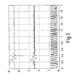
- Figure 3 shows waveforms, which of one in the close range working radar has been added are.
- the upper signal curve is undisturbed.
- the middle one Signal curve is influenced by a strong interference, which in the present case is an example of an FMCW radar is caused.
- the lower signal is through a very strong disturbance influenced by the same type.
- FIG. 4 schematically shows the structure of a sensor 20, which is used in the vicinity of the radar.
- the sensor 20 is an electronic control unit 22 Voltage provided, for example a Voltage of 8 V. This voltage is in a DC-DC converter 24 transformed so that ultimately the supply voltage available for the sensor components is set, for example 5 V.
- a carrier frequency of for example 24 GHz is from a local oscillator 26 delivered.
- This local oscillator 26 is equipped with a Preload, which ultimately comes from the one Clock generator 28 made available by means of pulses a converter 30 is generated.
- the clock generator 28 generated pulses for example a frequency of 5 MHz can be used to modulate the Local oscillator 26 provided carrier signals used.
- This modulation takes place in the transmission branch by the switch 32, which is provided by a pulse shaper 46 is switched.
- the pulse shaper 46 is in turn from the clock frequency of the clock generator 28 driven.
- the Pulsed signals thus generated are generated by the antenna 34 sent out. In the event of a reflection of the signals which are transmitted by the antenna 34, these will received by the receiving antenna 36.
- a first Mixer 40 delivers an I signal while the second mixer 42 outputs a Q signal.
- the switch is from a pulse generator 48 driven, which with respect to the pulses output by the pulse generator 46 by a delay ⁇ t outputs delayed pulses. This delay is available through a delay circuit 50 posed. Via a microcontroller 52, which one digital signal processor has the delay delay circuit 50. this happens via a first analog output 54 of the microcontroller 52. Be through a second analog output 60 the I- or processed by an amplifier 56 respectively Q signals through further variable amplification in the Amplifier 58 affects. Influencing this variable Amplifier 58 takes place by means of a second analog Output 60 of the microcontroller 52. The output signal of variable amplifier 58 becomes an analog Input 62 of the microcontroller 52 supplied. The microcontroller 52 communicates via an input-output bus 64 (I / O bus) with the electronic control unit 22.
- I / O bus input-output bus 64
- the transmission branch of the radar sensor 20 deactivated according to FIG. 4. So there are no transmission signals more transmitted from the transmission antenna 34. Indeed continue to be correlation pulses from the pulse generator 48 given to the receiving branch of the radar sensor 20. provides in this state, in which the transmission branch is switched off is out that destination information is still received a false signal can be inferred from this become. If static target information appears, this can be done through software, for example in the electronic control unit 22 can be eliminated. Deterministically changeable goals can be determined by a another choice of the center frequency of the local oscillator 26 or the pulse repetition frequency, which is from the clock generator 28 is made available to be eliminated.
- a circuit is shown, which largely corresponds to the circuit according to FIG. 4. additionally a notch filter 66 is provided in the receiving branch. This can be used particularly advantageously, if monochromatic or almost monochromatic There are faults.
- the circuit shown in Figure 5 is furthermore in addition to the components according to FIG a PLL circuit 68 and an additional mixer 70 fitted. By tuning this PLL source 68 the interference frequency can be determined means on the basis of the arrangement according to FIG it is no longer necessary to detune the carrier frequency.
- FIG. 6 shows a flow chart to explain a inventive method.
- CFAR constant false alarm rate
- step S05 an attempt is made in step S05 to Eliminate interference. This can be done, for example, by Change in the center frequency, by changing the pulse repetition frequency, through a notch filter or through a Modification scheme is changed.
- the elimination interference signals can also be software-based respectively.
- step S06 it is checked whether the fault was eliminated. If this is the case, normal operation can occur be passed over. Otherwise, in Step S07 invalidates the measurement.
Abstract
Description
Die Erfindung betrifft ein Verfahren zum Erkennen gestörter Zustände einer Radareinrichtung. Die Erfindung betrifft ferner eine Radareinrichtung.The invention relates to a method for detecting disturbed States of a radar device. The invention relates also a radar device.
Für Radareinrichtungen gibt es zahlreiche Anwendungen auf den verschiedensten Gebieten der Technik. Beispielsweise ist für die Nahbereichssensorik in Kraftfahrzeugen der Einsatz von Radar-Sensoren möglich.There are numerous applications for radar equipment the most diverse areas of technology. For example is for the short range sensors in motor vehicles Use of radar sensors possible.
Grundsätzlich werden bei Radareinrichtungen elektromagnetische Wellen von einer Sendeantenne abgestrahlt. Treffen diese elektromagnetischen Wellen auf ein Hindernis, so werden sie reflektiert und nach der Reflektion von einer anderen oder derselben Antenne wieder empfangen. Nachfolgend werden die empfangenen Signale einer Signalverarbeitung und Signalauswertung zugeführt.Basically, radar devices become electromagnetic Waves emitted by a transmission antenna. To meet these electromagnetic waves on an obstacle, so they are reflected and after the reflection by one received another or the same antenna. following the signals received are signal processing and signal evaluation supplied.
Beispielsweise werden in Kraftfahrzeugen Radarsensoren für die Messung des Abstands zu Zielen und/oder der Relativgeschwindigkeit bezüglich solcher Ziele außerhalb des Kraftfahrzeuges eingesetzt. Als Ziele kommen zum Beispiel vorausfahrende oder parkende Kraftfahrzeuge, Fußgänger, Radfahrer oder Einrichtungen im Umfeld des Fahrzeuges in Frage.For example, radar sensors are used in motor vehicles for measuring the distance to targets and / or the relative speed regarding such goals outside the Motor vehicle used. For example, as targets vehicles in front or parked, pedestrians, Cyclists or facilities in the vicinity of the vehicle in Question.
Figur 1 zeigt eine schematische Darstellung einer Radareinrichtung
mit einem Korrelationsempfänger des Standes
der Technik. Ein Sender 300 wird durch eine Pulserzeugung
302 veranlasst, über eine Antenne 304 ein Sendesignal 306
abzustrahlen. Das Sendesignal 306 trifft auf ein Zielobjekt
308, wo es reflektiert wird. Das Empfangssignal 310
wird von der Antenne 312 empfangen. Diese Antenne 312
kann mit der Antenne 304 identisch sein. Nach dem Empfang
des Empfangssignals 310 durch die Antenne 312 wird dieses
dem Empfänger 314 übermittelt und nachfolgend über eine
Einheit 316 mit Tiefpass und Analog/Digital-Wandlung
einer Signalauswertung 318 zugeführt. Die Besonderheit
bei dem Korrelationsempfänger besteht darin, dass der
Empfänger 314 von der Pulserzeugung 302 ein Referenzsignal
320 erhält. Die von dem Empfänger 314 empfangenen
Empfangssignale 310 werden in dem Empfänger 314 mit dem
Referenzsignal 320 gemischt. Durch die Korrelation kann
auf der Grundlage der zeitlichen Verzögerung vom Aussenden
bis zum Empfangen der Radarimpulse beispielsweise auf
die Entfernung eines Zielobjektes geschlossen werden.Figure 1 shows a schematic representation of a radar device
with a correlation receiver of the stand
of the technique. A
Es ist möglich, an einem Fahrzeug beispielsweise zwischen
4 und 16 gleichartige Sensoren zu betreiben. Diese sind
räumlich in einer Weise angeordnet, dass sie sich gegenseitig
praktisch nicht beeinflussen. Nähert man sich
jedoch anderen Fahrzeugen, wie etwa bei einem Einparkvorgang
oder beim Stop & Go, so können Störungen auftreten. It is possible, for example, on a
Ebenfalls ist es möglich, dass Störungen durch andersartige Funkdienste auftreten, so dass auf diese Weise scheinbare Ziele erzeugt werden. Ein solches fehlerhaftes Erkennen eines scheinbaren Ziels ist nachteilig und kann mitunter sogar zu Risiken während des Fahrbetriebs führen.It is also possible that interference from other types Radio services occur, so this way apparent goals are generated. Such a flawed one Recognizing an apparent goal is disadvantageous and can sometimes even lead to risks while driving.
Die Erfindung besteht in einem Verfahren zum Erkennen gestörter Zustände einer Radareinrichtung mit den Schritten: Erkennen von Unregelmäßigkeiten beim Empfang von Signalen, Deaktivieren des Sendezweigs und Erkennen der An- oder Abwesenheit von Zielsignalen. Wird im Rahmen des erfindungsgemäßen Verfahrens also erkannt, dass Unregelmäßigkeiten im Empfangsteil auftreten, beispielsweise sehr schnell wechselnde Ziele, Ziele mit hohen Geschwindigkeiten oder Ziele mit sich sprunghaft ändernden Entfernungen, so wird angenommen, dass eine Störung vorliegt. Ebenfalls kann eine Störung darin bestehen, dass der Sensor blind ist, das heißt überhaupt keine Ziele mehr erkennt. In diesen Fällen wird der Sendezweig der Radareinrichtung abgeschaltet oder allgemeiner formuliert, es wird vermieden, dass ein Sendesignal von der Radareinrichtung ausgesendet wird. Die Korrelationspulse werden jedoch weiterhin auf den Mischer des Empfangszweigs gegeben. Nun wird im Rahmen des erfindungsgemäßen Verfahrens ermittelt, ob bei deaktiviertem Sender Zielinformationen nach wie vor erfasst werden. Ist dies der Fall, so wird auf eine Störung geschlossen. Es ist also möglich, zunächst durch das Feststellen von Unregelmäßigkeiten und die nachfolgende Prüfung auf eine fehlerhafte Zielinformation rückzuschließen.The invention consists in a method for recognition disturbed states of a radar device with the steps: Detect irregularities when receiving Signals, deactivating the transmission branch and recognizing the Presence or absence of target signals. Is part of the The method according to the invention thus recognized that irregularities occur in the receiving part, for example very quickly changing targets, targets at high speeds or targets with rapidly changing distances, it is assumed that there is a fault. Another problem can be that the sensor is blind, that means no targets at all recognizes more. In these cases, the transmission branch is the Radar device switched off or formulated more generally, it is avoided that a transmission signal from the Radar device is broadcast. The correlation pulses however, continue to be on the mixer of the receiving branch given. Now in the context of the invention The method determines whether target information is present when the transmitter is deactivated are still recorded. Is this the If so, a fault is concluded. So it is possible, first by detecting irregularities and the subsequent check for a faulty one Infer target information.
Vorzugsweise werden im Anschluss an das Erkennen der Anwesenheit von Zielsignalen diese auf Softwarebasis eliminiert. Dies ist insbesondere dann möglich, wenn statische Informationen vorliegen, etwa die Information, dass sich ein Ziel in einer bestimmten Entfernung befindet.Following the recognition of the Presence of target signals these on a software basis eliminated. This is particularly possible if static information is available, such as the information that a target is at a certain distance.
Das erfindungsgemäße Verfahren kann jedoch auch dadurch in vorteilhafter Weise weitergebildet sein, dass im Anschluss an das Erkennen der Anwesenheit von Zielsignalen diese durch eine Veränderung der Mittenfrequenz der Radareinrichtung eliminiert werden. Diese Variante kommt insbesondere für das Eliminieren deterministisch veränderlicher Ziele zum Einsatz. Für eine Veränderung der Mittenfrequenz kommt beispielsweise eine periodische oder ein chaotische Verschiebung in Frage.However, the method according to the invention can also do so be further developed in an advantageous manner that subsequently recognition of the presence of target signals this by changing the center frequency of the radar device be eliminated. This variant is coming especially for eliminating deterministically changeable Goals in use. For a change in Center frequency comes for example a periodic or a chaotic shift in question.
Es kann ebenfalls nützlich sein, dass das erfindungsgemäße Verfahren in der Weise durchgeführt wird, dass im Anschluss an das Erkennen der Anwesenheit von Zielsignalen diese durch eine Veränderung der Pulswiederholfrequenz der Radareinrichtung eliminiert werden. Auch hierdurch ist es möglich, die Radareinrichtung in der Weise zu verändern, dass Scheinziele nicht mehr nachgewiesen werden, wobei echte Ziele jedoch unverändert berücksichtigt werden.It may also be useful that the invention Process is carried out in such a way that Connection to the detection of the presence of target signals this by changing the pulse repetition rate the radar device can be eliminated. This too it is possible to use the radar device in the way to change that sham goals are no longer demonstrated are considered, but real goals remain unchanged become.
Ebenfalls kann vorteilhaft sein, dass im Anschluss an das Erkennen der Anwesenheit von Zielsignalen diese durch einen Notchfilter eliminiert werden. Dies ist insbesondere nützlich, wenn die Störung monochromatisch oder nahezu monochromatisch ist. Die störenden Frequenzen werden durch den Notchfilter eliminiert, so dass es letztlich zu einem störungsfreien Radarbetrieb kommt.It can also be advantageous that after the Detect the presence of target signals by this a notch filter can be eliminated. This is particularly so useful when the disorder is monochromatic or near is monochromatic. The interfering frequencies are eliminated by the notch filter, so it ultimately ends up trouble-free radar operation.
Es kann ebenfalls von Vorteil sein, wenn das erfindungsgemäße Verfahren so weitergebildet ist, dass im Anschluss an das Erkennen der Anwesenheit von Zielsignalen diese durch Pulscodierung eliminiert werden. Beispielsweise kommt die Umschaltung von Pulsmodulation auf Frequenzmodulation in Frage. Ebenfalls ist es denkbar, die Pulse mittels eines PN-Codierverfahrens (PN: "Pseudo Noise") zu codieren.It can also be advantageous if the invention Process is further developed so that afterwards recognizing the presence of target signals this be eliminated by pulse coding. For example comes the switch from pulse modulation to frequency modulation in question. It is also conceivable for the pulses by means of a PN coding method (PN: "pseudo noise") encode.
Nützlicherweise kann das Verfahren auch so fortgebildet sein, dass im Anschluss an das Erkennen der An- oder Abwesenheit von Zielsignalen ein Dauerträgersignal auf einen Mischer im Empfangszweig gegeben wird und mittels Verstimmen des Dauerträgersignals die Störträgerfrequenz bestimmt wird. Dies ist insbesondere vorteilhaft, wenn sporadische Signale vorliegen. Durch den Dauerträger am Mischer im Empfangszweig können die empfangenen Signale auf eine niedrige Frequenzlage, beispielsweise in einen Bereich unterhalb von 2 GHz umgesetzt werden. Durch Verstimmung der Frequenz kann die Störträgerfrequenz bestimmt werden.The method can usefully be further developed in this way be that after recognizing the or Absence of target signals a permanent carrier signal a mixer is given in the receiving branch and by means of Detune the continuous carrier signal the interference carrier frequency is determined. This is particularly advantageous if sporadic signals are present. By the permanent carrier on Mixers in the receiving branch can receive the signals received to a low frequency position, for example in one Range below 2 GHz can be implemented. By upset the frequency can determine the interference carrier frequency become.
In vergleichbarer Weise kann das Verfahren so ausgeführt werden, dass im Anschluss an das Erkennen der An- oder Abwesenheit von Zielsignalen mittels Durchstimmen einer PLL-Quelle die Störträgerfrequenz bestimmt wird. Die Bereitstellung einer derartigen PLL-Quelle im Empfangszweig macht einen variablen Träger entbehrlich. Allerdings ist ein erhöhter Schaltungsaufwand in dem betreffenden Frequenzbereich, beispielsweise im Bereich von 2 GHz, erforderlich.The method can be carried out in a comparable manner be that after recognizing the or Absence of target signals by tuning one PLL source the interference carrier frequency is determined. The Provision of such a PLL source in the reception branch makes a variable carrier unnecessary. Indeed is an increased circuit complexity in the concerned Frequency range, for example in the range of 2 GHz, required.
Vorzugsweise wird im Falle des Nichteliminierens der Störsignale die Messung als ungültig erklärt. Lassen sich also durch die im Rahmen des erfindungsgemäßen Verfahrens ausgeführten Maßnahmen die Störziele nicht beseitigen, so wird die gesamte Messung verworfen, so dass das Verfahren letztlich eine zuverlässige Bestimmung von echten Zielen und ein Eliminieren von Scheinzielen ermöglicht.In the case of non-elimination, the Interference signals the measurement declared invalid. Can be that is, in the context of the inventive method implemented measures do not eliminate the disruptive targets, so the entire measurement is discarded, so the procedure ultimately a reliable determination of real goals and enables elimination of false targets.
Die Erfindung betrifft ferner eine Radareinrichtung mit Mitteln zum Erkennen von Unregelmäßigkeiten beim Empfang von Signalen, Mitteln zum Deaktivieren des Sendezweigs und Mitteln zum Erkennen der An- oder Abwesenheit von Zielsignalen. Mit einer derartigen Radareinrichtung lassen sich die erfindungsgemäßen Vorteile des Verfahrens zum Erkennen gestörter Zustände umsetzen.The invention further relates to a radar device Means for detecting irregularities in reception of signals, means for deactivating the transmission branch and means for recognizing the presence or absence of Target signals. Leave with such a radar device the advantages of the method according to the invention implement to recognize disturbed states.
Die Radareinrichtung ist besonders nützlich, wenn im Anschluss an das Erkennen der Anwesenheit von Zielsignalen diese auf Softwarebasis eliminierbar sind. Insbesondere können fehlerhafte statische Informationen bei einer derartigen Auslegung der Radareinrichtung eliminiert werden.The radar device is particularly useful when in Connection to the detection of the presence of target signals these can be eliminated on a software basis. In particular can contain incorrect static information in a such design of the radar device eliminated become.
Die erfindungsgemäße Radareinrichtung ist in vorteilhafter Weise dadurch weitergebildet, dass im Anschluss an das Erkennen der Anwesenheit von Zielsignalen diese durch eine Veränderung der Mittenfrequenz der Radareinrichtung eliminierbar sind. Die Mittenfrequenz kann periodisch oder chaotisch verändert werden. Dies dient vorzugsweise dem Eliminieren deterministisch veränderlicher Ziele.The radar device according to the invention is advantageous Way further developed by following recognizing the presence of target signals through them a change in the center frequency of the radar device can be eliminated. The center frequency can be periodic or be changed chaotically. This is preferably used the elimination of deterministically changeable goals.
In einer bevorzugten Ausführungsform der Radareinrichtung kann es auch nützlich sein, dass im Anschluss an das Erkennen der Anwesenheit von Zielsignalen diese durch eine Veränderung der Pulswiederholfrequenz der Radareinrichtung eliminierbar sind. Dies ist eine weitere Variante zum Eliminieren von Scheinzielen, wobei hier jedoch als wesentliche Maßnahme eine Veränderung der Pulswiederholfrequenz vorgenommen wird.In a preferred embodiment of the radar device it may also be useful that following that Detect the presence of target signals by this a change in the pulse repetition frequency of the radar device can be eliminated. This is another variant to eliminate false targets, but here as a major measure, a change in the pulse repetition rate is made.
Ebenfalls kann vorgesehen sein, dass im Anschluss an das Erkennen der Anwesenheit von Zielsignalen diese durch einen Notchfilter eliminierbar sind. Eine derartige Radareinrichtung kann insbesondere monochromatische Störungen eliminieren.It can also be provided that following the Detect the presence of target signals by this a notch filter can be eliminated. Such a radar device can be particularly monochromatic disorders eliminate.
In einer weiteren bevorzugten Ausführungsform der erfindungsgemäßen Radareinrichtung kann von Vorteil sein, dass im Anschluss an das Erkennen der Anwesenheit von Zielsignalen diese durch Pulscodierung eliminierbar sind. Für die Pulscodierung können unterschiedliche Modulationsverfahren verwendet werden, sowohl einzeln als auch in Kombination.In a further preferred embodiment of the invention Radar equipment can be advantageous in that following the detection of the presence of target signals these can be eliminated by pulse coding. For the pulse coding can use different modulation methods can be used both individually and in combination.
Die Radareinrichtung ist vorteilhaft dadurch weitergebildet, dass im Anschluss an das Erkennen der An- oder Abwesenheit von Zielsignalen ein Dauerträgersignal auf einen Mischer im Empfangszweig gegeben wird und mittels Verstimmen des Dauerträgersignals die Störträgerfrequenz bestimmbar ist. Da sporadische Signale durch die beschriebenen Veränderungen der Signale nicht eliminierbar sind, kann die Radareinrichtung so ausgelegt sein, dass durch einen Dauerträger am Mischer im Empfangszweig die empfangenen Signale auf eine niedrige Frequenzlage, beispielsweise in einen Bereich unterhalb von 2 GHz umgesetzt werden. Durch Verstimmung der Frequenz kann die Störträgerfrequenz bestimmt werden.The radar device is advantageously developed by that after recognizing the presence or absence of target signals a permanent carrier signal on one Mixer is given in the receiving branch and by detuning of the continuous carrier signal the interference carrier frequency is determinable. Because sporadic signals by the described Changes in the signals cannot be eliminated are, the radar device can be designed so that by a permanent support on the mixer in the receiving branch received signals at a low frequency, for example implemented in a range below 2 GHz become. By detuning the frequency, the Interference carrier frequency can be determined.
In einer weiteren Ausführungsform kann es jedoch auch nützlich sein, dass im Anschluss an das Erkennen der Anoder Abwesenheit von Zielsignalen mittels Durchstimmen einer PLL-Quelle die Störträgerfrequenz bestimmbar ist. Diese Maßnahme ist vergleichbar mit dem Verstimmen der Dauerträgerfrequenz am Mischer im Empfangszweig. Durch die Bereitstellung einer PLL-Quelle kann eine variable Trägerfrequenz jedoch entbehrlich sein.In a further embodiment, however, it can also be useful after recognizing the anoder Absence of target signals by tuning a PLL source the interference carrier frequency can be determined. This measure is comparable to the detuning of the Continuous carrier frequency at the mixer in the receiving branch. By the provision of a PLL source can be a variable However, carrier frequency can be dispensed with.
Vorzugsweise wird im Falle des Nichteliminierens der Störsignale die Messung als ungültig erklärt. Scheitern die Maßnahmen zum Eliminieren der Störsignale, so wird die gesamte Messung verworfen. Die Radareinrichtung ermöglicht letztlich also eine zuverlässige Bestimmung von echten Zielen und ein Eliminieren von Scheinzielen.In the case of non-elimination, the Interference signals the measurement declared invalid. fail the measures to eliminate the interference signals, so discarded the entire measurement. The radar device enables ultimately a reliable determination of real goals and eliminating sham goals.
Der Erfindung liegt die überraschende Erkenntnis zugrunde, dass es durch das Erkennen von Unregelmäßigkeiten beim Empfang von Signalen und durch das nachfolgende Prüfen der Zielsignale bei Veränderung des Betriebs der Radareinrichtung möglich ist, Störsignale zu erkennen und zu eliminieren. Die Störerkennung kann ferner für Multi-Sensor-Plattformen zur gegenseitigen Synchronisation beziehungsweise Frequenzabstimmung der Sensoren untereinander genutzt werden. Die Erfindung lässt sich im Kfz-Bereich vorteilhaft einsetzten so dass letztlich Fahrkomfort und Fahrsicherheit erhöht werden.The invention is based on the surprising finding that it is by recognizing irregularities when receiving signals and by the following Checking the target signals when the operation of the Radar device is possible to detect interference signals and to eliminate. The fault detection can also be used for multi-sensor platforms for mutual synchronization or frequency coordination of the sensors with each other be used. The invention can be used in the automotive field use advantageously so that ultimately driving comfort and driving safety can be increased.
Die Erfindung wird nun mit Bezug auf die begleitenden Zeichnungen anhand bevorzugter Ausführungsformen beispielhaft erläutert.The invention will now be described with reference to the accompanying Exemplary drawings based on preferred embodiments explained.
Dabei zeigt:
Figur 1- eine Radareinrichtung des Standes der Technik;
Figur 2- ein Kraftfahrzeug mit Radareinrichtungen;
- Figur 3
- Signale mit unterschiedlich starken Störungen;
- Figur 4
- eine Radareinrichtung zur Durchführung der vorliegenden Erfindung;
Figur 5- eine weitere Radareinrichtung zur Durchführung der vorliegenden Erfindung; und
- Figur 6
- ein Flussdiagramm zur Erläuterung eines erfindungsgemäßen Verfahrens.
- Figure 1
- a prior art radar device;
- Figure 2
- a motor vehicle with radar devices;
- Figure 3
- Signals with different levels of interference;
- Figure 4
- a radar device for carrying out the present invention;
- Figure 5
- another radar device for carrying out the present invention; and
- Figure 6
- a flowchart to explain a method according to the invention.
In Figur 2 ist ein Kraftfahrzeug 10 dargestellt, an welchem
mehrere Radarsensoren 12 angeordnet sind. Die Radarsensoren
sind über ein Buskonzept untereinander und mit
Steuerungs- und Kontrolleinheiten verbunden, wobei insbesondere
eine Einheit 14 zur Bereitstellung einer Einparkhilfe
und zur Detektion eines toten Winkels, eine Einheit
16 für die Precrash-Funktion und eine Einheit 18 für Stop
& Go vorgesehen sind.FIG. 2 shows a
Figur 3 zeigt Signalverläufe, welche von einer im Nahbereich arbeitenden Radareinrichtung aufgenommen worden sind. Der obere Signalverlauf ist ungestört. Der mittlere Signalverlauf ist durch eine starke Störung beeinflusst, welche im vorliegenden Fall beispielhaft von einem FMCW-Radar verursacht wird. Das untere Signal ist durch eine sehr starke Störung vom selbem Typ beeinflusst.Figure 3 shows waveforms, which of one in the close range working radar has been added are. The upper signal curve is undisturbed. The middle one Signal curve is influenced by a strong interference, which in the present case is an example of an FMCW radar is caused. The lower signal is through a very strong disturbance influenced by the same type.
Figur 4 zeigt schematisch den Aufbau eines Sensors 20,
welcher im Radarnahbereich eingesetzt wird. Dem Sensor 20
wird von einer elektronischen Steuerungseinheit 22 eine
Spannung zur Verfügung gestellt, beispielsweise eine
Spannung von 8 V. Diese Spannung wird in einem DC-DC-Wandler
24 transformiert, so dass letztlich die Versorgungsspannung
für die Sensorkomponenten zur Verfügung
gestellt wird, beispielsweise 5 V. Eine Trägerfrequenz
von beispielsweise 24 GHz wird von einem Lokaloszillator
26 geliefert. Dieser Lokaloszillator 26 wird mit einer
Vorspannung versorgt, welche letztlich aus den von einem
Taktgenerator 28 zur Verfügung gestellten Pulsen mittels
eines Wandlers 30 erzeugt wird. Die von dem Taktgenerator
28 erzeugten Pulse, die beispielsweise eine Frequenz von
5 MHz aufweisen können, werden zur Modulation der von dem
Lokaloszillator 26 zur Verfügung gestellten Trägersignale
verwendet. Diese Modulation erfolgt in dem Sendezweig
durch den Schalter 32, welcher von einem Impulsformer 46
geschaltet wird. Der Impulsformer 46 wird wiederum von
der Taktfrequenz des Taktgenerators 28 angesteuert. Die
so erzeugten gepulsten Signale werden von der Antenne 34
ausgesendet. Im Falle einer Reflektion der Signale, welche
von der Antenne 34 ausgesendet werden, werden diese
von der Empfangsantenne 36 empfangen. Nach Verstärkung
der empfangenen Signale in einem Verstärker 38 werden die
Signale zwei Mischern 40, 42 zugeführt, wobei ein erster
Mischer 40 ein I-Signal liefert, während der zweite Mischer
42 ein Q-Signal ausgibt. In den Mischern 40, 42
werden die empfangenen Signale mit den gepulsten Signalen
des Lokaloszillators 26 gemischt, wobei dieses Pulsen
über einen Schalter 44 erfolgt. Der Schalter wird von
einem Impulsgeber 48 angesteuert, welcher bezüglich der
von dem Impulsgeber 46 ausgegebenen Impulse um eine Verzögerung
Δt verzögerte Impulse ausgibt. Diese Verzögerung
wird durch eine Verzögerungsschaltung 50 zur Verfügung
gestellt. Über einen Microcontroller 52, welcher einen
digitalen Signalprozessor aufweist wird die Verzögerung
der Verzögerungsschaltung 50 beeinflusst. Dies erfolgt
über einen ersten analogen Ausgang 54 des Microcontrollers
52. Über einen zweiten analogen Ausgang 60 werden
die von einem Verstärker 56 verarbeiteten I- beziehungsweise
Q-Signale durch weitere variable Verstärkung in dem
Verstärker 58 beeinflusst. Die Beeinflussung dieses variablen
Verstärkers 58 erfolgt mittels eines zweiten analogen
Ausgangs 60 des Microcontrollers 52. Das Ausgangssignal
des variablen Verstärkers 58 wird einem analogen
Eingang 62 des Microcontrollers 52 zugeführt. Der Microcontroller
52 kommuniziert über einen Eingabe-Ausgabe-Bus
64 (I/O-Bus) mit der elektronischen Steuerungseinheit 22.FIG. 4 schematically shows the structure of a
Wird nun im Rahmen des erfindungsgemäßen Verfahrens erkannt,
dass beim Empfang von Signalen Unregelmäßigkeiten
auftreten, so wird der Sendezweig des Radarsensors 20
gemäß Figur 4 deaktiviert. Somit werden keine Sendesignale
mehr von der Sendeantenne 34 ausgesendet. Allerdings
werden weiterhin Korrelationspulse von dem Impulsgeber 48
auf den Empfangszweig des Radarsensors 20 gegeben. Stellt
sich in diesem Zustand, bei dem der Sendezweig abgeschaltet
ist, heraus, dass nach wie vor Zielinformation empfangen
wird, so kann daraus auf ein Scheinsignal geschlossen
werden. Treten statische Zielinformationen auf,
so können diese durch Software, beispielsweise in der
elektronischen Steuerungseinheit 22 eliminiert werden.
Deterministisch veränderliche Ziele können durch eine
andere Wahl der Mittenfrequenz des Lokaloszillators 26
oder der Pulswiederholfrequenz, welche von dem Taktgenerator
28 zur Verfügung gestellt wird, beseitigt werden.
Treten sporadische Signale auf, so können diese nicht
allein durch die bislang beschriebenen Maßnahmen berücksichtigt
werden. Dem wird dadurch Rechnung getragen, dass
an die Mischer 40, 42 ein Dauerträger angelegt wird,
wodurch die empfangenen Signale auf eine niedrigere Frequenzlage
umgesetzt werden. Durch Verstimmung der Trägerfrequenz
kann die Störträgerfrequenz bestimmt werden.If it is now recognized in the context of the method according to the invention,
that when receiving signals irregularities
occur, the transmission branch of the
In Figur 5 ist eine Schaltung dargestellt, welche weitgehend
der Schaltung gemäß Figur 4 entspricht. Zusätzlich
ist im Empfangszweig ein Notchfilter 66 vorgesehen. Dieses
kann insbesondere dann vorteilhaft zum Einsatz kommen,
wenn monochromatische oder nahezu monochromatische
Störungen vorliegen. Die Schaltung gemäß Figur 5 ist
ferner zusätzlich zu den Komponenten gemäß Figur 4 mit
einer PLL-Schaltung 68 und einem zusätzlichen Mischer 70
ausgestattet. Mittels eines Durchstimmens dieser PLL-Quelle
68 kann die Störfrequenz bestimmt werden, das
heißt auf der Grundlage der Anordnung gemäß Figur 5 ist
es nicht mehr erforderlich, die Trägerfrequenz zu verstimmen.In Figure 5, a circuit is shown, which largely
corresponds to the circuit according to FIG. 4. additionally
a
Figur 6 zeigt ein Flussdiagramm zur Erläuterung eines erfindungsgemäßen Verfahrens.FIG. 6 shows a flow chart to explain a inventive method.
Zunächst wird die Bedeutung der dargestellten Verfahrensschritte aufgelistet:
- S01:
- Normalbetrieb.
- S02:
- Unregelmäßigkeiten? Blindheit?
- S03:
- Sender abschalten; gepulster Empfang oder Dauerempfang.
- S04:
- Analyse der Störung.
- S05:
- Versuch, Störung zu eliminieren.
- S06:
- Störung eliminiert?
- S07:
- Messung ungültig.
- S01:
- Normal operation.
- S02:
- Irregularities? Blindness?
- S03:
- Switch off transmitter; pulsed reception or continuous reception.
- S04:
- Analysis of the fault.
- S05:
- Attempt to eliminate interference.
- S06:
- Interference eliminated?
- S07:
- Measurement invalid.
Ausgehend vom Normalbetrieb in Schritt S01 wird in Schritt S02 geprüft, ob Unregelmäßigkeiten beim Empfang vorliegen oder ob der Sensor blind ist. Ebenfalls kann als Störerkennung die CFAR-Methode eingesetzt werden (CFAR = "constant false alarm rate"). Dabei wird in einem bestimmten Fenster die Rauschamplitude gemessen. Die Auswertestelle wird dabei so gewählt, dass das Signal-Rauschverhältnis konstant bleibt. Eine Erhöhung des Rauschanteils kann dann als Störerkennung interpretiert werden. Wird in Schritt S02 erkannt, dass keine Unregelmäßigkeiten und keine Blindheit vorliegen, so geht der Programmablauf in den Normalbetrieb über. Im anderen Fall, das heißt es liegen Unregelmäßigkeiten beziehungsweise eine Blindheit des Sensors vor, so wird in Schritt S03 der Sender deaktiviert. Weiterhin erfolgt ein gepulster Empfang beziehungsweise ein Dauerempfang. In Schritt S04 wird nachfolgend die vorliegende Störung analysiert. Im Anschluss daran wird in Schritt S05 versucht, die Störung zu eliminieren. Dies kann beispielsweise durch Änderung der Mittenfrequenz, durch Änderung der Pulswiederholfrequenz, durch einen Notchfilter oder durch eine Änderung des Modulationsschemas erfolgen. Die Eliminierung von Störsignalen kann ebenfalls auf Softwarebasis erfolgen. In Schritt S06 wird überprüft, ob die Störung eliminiert wurde. Ist dies der Fall, so kann zu Normalbetrieb übergegangen werden. Im anderen Fall wird in Schritt S07 die Messung für ungültig erklärt.Starting from normal operation in step S01, in Step S02 checked whether there were any irregularities in reception or whether the sensor is blind. Can also the CFAR method can be used as fault detection (CFAR = "constant false alarm rate"). It is in one measured the noise amplitude in certain windows. The The evaluation point is chosen so that the signal-to-noise ratio remains constant. An increase in Noise component can then be interpreted as interference detection become. It is recognized in step S02 that there are no irregularities and there is no blindness Program sequence in normal operation. In the other Case, that means there are irregularities respectively If the sensor is blind, step S03 the transmitter deactivated. There is also a pulsed Reception or a permanent reception. In step S04 the present fault is subsequently analyzed. Following this, an attempt is made in step S05 to Eliminate interference. This can be done, for example, by Change in the center frequency, by changing the pulse repetition frequency, through a notch filter or through a Modification scheme is changed. The elimination interference signals can also be software-based respectively. In step S06 it is checked whether the fault was eliminated. If this is the case, normal operation can occur be passed over. Otherwise, in Step S07 invalidates the measurement.
Die vorhergehende Beschreibung der Ausführungsbeispiele gemäß der vorliegenden Erfindung dient nur zu illustrativen Zwecken und nicht zum Zwecke der Beschränkung der Erfindung. Im Rahmen der Erfindung sind verschiedene Änderungen und Modifikationen möglich, ohne den Umfang der Erfindung sowie ihre Äquivalente zu verlassen.The preceding description of the exemplary embodiments according to the present invention is for illustrative purposes only Purposes and not for the purpose of restricting the Invention. Various are within the scope of the invention Changes and modifications possible without the scope leave the invention and its equivalents.
Claims (18)
Applications Claiming Priority (2)
| Application Number | Priority Date | Filing Date | Title |
|---|---|---|---|
| DE10108582A DE10108582A1 (en) | 2001-02-22 | 2001-02-22 | Method for detecting disturbed states of a radar device and radar device |
| DE10108582 | 2001-02-22 |
Publications (2)
| Publication Number | Publication Date |
|---|---|
| EP1235078A2 true EP1235078A2 (en) | 2002-08-28 |
| EP1235078A3 EP1235078A3 (en) | 2003-03-26 |
Family
ID=7675144
Family Applications (1)
| Application Number | Title | Priority Date | Filing Date |
|---|---|---|---|
| EP01129146A Withdrawn EP1235078A3 (en) | 2001-02-22 | 2001-12-08 | Method for detecting radar system failures and radar system |
Country Status (3)
| Country | Link |
|---|---|
| US (1) | US6618003B2 (en) |
| EP (1) | EP1235078A3 (en) |
| DE (1) | DE10108582A1 (en) |
Cited By (2)
| Publication number | Priority date | Publication date | Assignee | Title |
|---|---|---|---|---|
| WO2009153629A1 (en) * | 2008-06-19 | 2009-12-23 | Toyota Jidosha Kabushiki Kaisha | Calibration method with sequential boresight adjustment of multiple automotive radar devices |
| WO2020074417A1 (en) * | 2018-10-11 | 2020-04-16 | Robert Bosch Gmbh | Method for ascertaining the validity of radar measurement values in order to determine a state of occupancy of a parking space |
Families Citing this family (37)
| Publication number | Priority date | Publication date | Assignee | Title |
|---|---|---|---|---|
| DE10142170A1 (en) * | 2001-08-29 | 2003-03-20 | Bosch Gmbh Robert | Pulsed radar acquiring immediate surroundings of vehicles, includes high frequency oscillator connected to pulse modulators for transmission and reception |
| US7474705B2 (en) * | 2002-08-16 | 2009-01-06 | Wisair Ltd | Scalable ultra-wide band communication system |
| JP4007498B2 (en) * | 2002-11-15 | 2007-11-14 | 三菱電機株式会社 | Automotive radar equipment |
| DE10254982A1 (en) | 2002-11-26 | 2004-06-03 | Robert Bosch Gmbh | Method and device for adaptive power control |
| JP2005181193A (en) * | 2003-12-22 | 2005-07-07 | Tdk Corp | Pulse-wave radar apparatus |
| DE112006001114T5 (en) * | 2005-05-16 | 2008-04-30 | Murata Manufacturing Co. Ltd. | radar |
| US8238863B2 (en) * | 2009-12-10 | 2012-08-07 | Qualcomm Incorporated | Methods and apparatuses for identifying and mitigating interference in a wireless signal |
| EP2390679B1 (en) * | 2010-05-27 | 2012-10-03 | Mitsubishi Electric R&D Centre Europe B.V. | Automotive radar with radio-frequency interference avoidance |
| US9008249B2 (en) | 2012-02-10 | 2015-04-14 | Qualcomm Incorporated | Detection and filtering of an undesired narrowband signal contribution in a wireless signal receiver |
| US9065686B2 (en) | 2012-11-21 | 2015-06-23 | Qualcomm Incorporated | Spur detection, cancellation and tracking in a wireless signal receiver |
| DE102016202805A1 (en) * | 2016-02-24 | 2017-08-24 | Bayerische Motoren Werke Aktiengesellschaft | Method and device for operating an environmental sensor of a vehicle |
| US10261179B2 (en) | 2016-04-07 | 2019-04-16 | Uhnder, Inc. | Software defined automotive radar |
| US9689967B1 (en) * | 2016-04-07 | 2017-06-27 | Uhnder, Inc. | Adaptive transmission and interference cancellation for MIMO radar |
| US9846228B2 (en) | 2016-04-07 | 2017-12-19 | Uhnder, Inc. | Software defined automotive radar systems |
| WO2017187299A2 (en) | 2016-04-25 | 2017-11-02 | Uhnder, Inc. | Successive signal interference mitigation |
| US9791551B1 (en) | 2016-04-25 | 2017-10-17 | Uhnder, Inc. | Vehicular radar system with self-interference cancellation |
| US9954955B2 (en) | 2016-04-25 | 2018-04-24 | Uhnder, Inc. | Vehicle radar system with a shared radar and communication system |
| WO2017187306A1 (en) | 2016-04-25 | 2017-11-02 | Uhnder, Inc. | Adaptive filtering for fmcw interference mitigation in pmcw radar systems |
| WO2017187304A2 (en) | 2016-04-25 | 2017-11-02 | Uhnder, Inc. | Digital frequency modulated continuous wave radar using handcrafted constant envelope modulation |
| US10573959B2 (en) | 2016-04-25 | 2020-02-25 | Uhnder, Inc. | Vehicle radar system using shaped antenna patterns |
| EP3449275A4 (en) | 2016-04-25 | 2020-01-01 | Uhnder, Inc. | Pmcw pmcw interference mitigation |
| US9753121B1 (en) | 2016-06-20 | 2017-09-05 | Uhnder, Inc. | Power control for improved near-far performance of radar systems |
| US9869762B1 (en) | 2016-09-16 | 2018-01-16 | Uhnder, Inc. | Virtual radar configuration for 2D array |
| JP6858523B2 (en) * | 2016-10-06 | 2021-04-14 | 京セラ株式会社 | Distance measuring device, distance measuring method and vehicle |
| US11454697B2 (en) | 2017-02-10 | 2022-09-27 | Uhnder, Inc. | Increasing performance of a receive pipeline of a radar with memory optimization |
| US10866306B2 (en) | 2017-02-10 | 2020-12-15 | Uhnder, Inc. | Increasing performance of a receive pipeline of a radar with memory optimization |
| WO2018146530A1 (en) | 2017-02-10 | 2018-08-16 | Uhnder, Inc. | Reduced complexity fft-based correlation for automotive radar |
| JP6881177B2 (en) * | 2017-09-15 | 2021-06-02 | 株式会社デンソー | Radar device |
| US11105890B2 (en) | 2017-12-14 | 2021-08-31 | Uhnder, Inc. | Frequency modulated signal cancellation in variable power mode for radar applications |
| US11656321B2 (en) * | 2018-07-23 | 2023-05-23 | Richwave Technology Corp. | Method of microwave motion detection with adaptive frequency control and related devices |
| US11474225B2 (en) | 2018-11-09 | 2022-10-18 | Uhnder, Inc. | Pulse digital mimo radar system |
| US11681017B2 (en) | 2019-03-12 | 2023-06-20 | Uhnder, Inc. | Method and apparatus for mitigation of low frequency noise in radar systems |
| DE102019214949A1 (en) * | 2019-09-27 | 2021-04-01 | Robert Bosch Gmbh | Method and device for recognizing an absorptive radome coating |
| WO2021144710A2 (en) | 2020-01-13 | 2021-07-22 | Uhnder, Inc. | Method and system for multi-chip operation of radar systems |
| JP2021092585A (en) * | 2021-02-26 | 2021-06-17 | 住友電気工業株式会社 | Radio wave sensor and detection program |
| CN113835077B (en) * | 2021-11-23 | 2022-02-11 | 中国空气动力研究与发展中心计算空气动力研究所 | Search radar target detection method and system based on variable pulse repetition frequency |
| US20240118380A1 (en) * | 2022-10-06 | 2024-04-11 | Nxp B.V. | Method and radar system for detecting targeted radar interference |
Citations (6)
| Publication number | Priority date | Publication date | Assignee | Title |
|---|---|---|---|---|
| US3115629A (en) * | 1957-03-01 | 1963-12-24 | Marconi Co Ltd | Repetitive signal systems for improving signal to noise ratio |
| US3916406A (en) * | 1963-02-20 | 1975-10-28 | Us Navy | Jamming cancellation device |
| US4901082A (en) * | 1988-11-17 | 1990-02-13 | Grumman Aerospace Corporation | Adaptive waveform radar |
| US5274380A (en) * | 1992-03-17 | 1993-12-28 | Fujitsu Limited | FM-CW radar |
| US6028548A (en) * | 1997-01-17 | 2000-02-22 | Automotive Systems Laboratory, Inc. | Vehicle collision radar with randomized FSK waveform |
| US6141371A (en) * | 1996-12-18 | 2000-10-31 | Raytheon Company | Jamming suppression of spread spectrum antenna/receiver systems |
Family Cites Families (9)
| Publication number | Priority date | Publication date | Assignee | Title |
|---|---|---|---|---|
| FR2278204A1 (en) * | 1974-07-12 | 1976-02-06 | Thomson Csf | MULTIPLE INTEGRATING DEVICE AND MULTI-FREQUENCY PULSE RADAR SYSTEM INCLUDING SUCH A DEVICE |
| GB1528164A (en) * | 1975-05-14 | 1978-10-11 | Marconi Co Ltd | Radar |
| US4622555A (en) * | 1982-09-02 | 1986-11-11 | Motorola, Inc. | Coded pulse Doppler radar with clutter-adaptive modulation and method therefore |
| US4717917A (en) * | 1985-06-26 | 1988-01-05 | Rockwell International Corporation | Alien radar suppression circuit |
| GB2270218B (en) * | 1992-07-15 | 1997-03-05 | Futaba Denshi Kogyo Kk | Transmitter for radio control device |
| US5565870A (en) * | 1993-06-28 | 1996-10-15 | Nissan Motor Co., Ltd. | Radar apparatus with determination of presence of target reflections |
| US6148020A (en) * | 1996-03-22 | 2000-11-14 | Sanyo Electric Co., Ltd. | Method and device for frequency hopping communication by changing a carrier frequency |
| US6208248B1 (en) * | 1999-01-28 | 2001-03-27 | Anro Engineering, Inc. | Quick response perimeter intrusion detection sensor |
| US6049302A (en) * | 1999-05-04 | 2000-04-11 | Boeing North American | Pulsed doppler radar system with small intermediate frequency filters |
-
2001
- 2001-02-22 DE DE10108582A patent/DE10108582A1/en not_active Withdrawn
- 2001-12-08 EP EP01129146A patent/EP1235078A3/en not_active Withdrawn
-
2002
- 2002-02-22 US US10/080,651 patent/US6618003B2/en not_active Expired - Fee Related
Patent Citations (6)
| Publication number | Priority date | Publication date | Assignee | Title |
|---|---|---|---|---|
| US3115629A (en) * | 1957-03-01 | 1963-12-24 | Marconi Co Ltd | Repetitive signal systems for improving signal to noise ratio |
| US3916406A (en) * | 1963-02-20 | 1975-10-28 | Us Navy | Jamming cancellation device |
| US4901082A (en) * | 1988-11-17 | 1990-02-13 | Grumman Aerospace Corporation | Adaptive waveform radar |
| US5274380A (en) * | 1992-03-17 | 1993-12-28 | Fujitsu Limited | FM-CW radar |
| US6141371A (en) * | 1996-12-18 | 2000-10-31 | Raytheon Company | Jamming suppression of spread spectrum antenna/receiver systems |
| US6028548A (en) * | 1997-01-17 | 2000-02-22 | Automotive Systems Laboratory, Inc. | Vehicle collision radar with randomized FSK waveform |
Cited By (2)
| Publication number | Priority date | Publication date | Assignee | Title |
|---|---|---|---|---|
| WO2009153629A1 (en) * | 2008-06-19 | 2009-12-23 | Toyota Jidosha Kabushiki Kaisha | Calibration method with sequential boresight adjustment of multiple automotive radar devices |
| WO2020074417A1 (en) * | 2018-10-11 | 2020-04-16 | Robert Bosch Gmbh | Method for ascertaining the validity of radar measurement values in order to determine a state of occupancy of a parking space |
Also Published As
| Publication number | Publication date |
|---|---|
| US6618003B2 (en) | 2003-09-09 |
| DE10108582A1 (en) | 2002-09-05 |
| US20020130811A1 (en) | 2002-09-19 |
| EP1235078A3 (en) | 2003-03-26 |
Similar Documents
| Publication | Publication Date | Title |
|---|---|---|
| EP1235078A2 (en) | Method for detecting radar system failures and radar system | |
| EP1601991B1 (en) | Method and device for the adaptive regulation of power | |
| DE19744185B4 (en) | Device for distance measurement by means of ultrasound | |
| EP1235079A2 (en) | Method of reducing interference in a radar device and radar apparatus | |
| DE102013218571A1 (en) | Device and method for lateral environment detection of a motor vehicle | |
| EP0269902B1 (en) | Process and device for measuring the distance between two objects, in particular between vehicles | |
| DE102013211846A1 (en) | Method for operating an environment detection system of a vehicle | |
| DE19924755A1 (en) | Distance detection device | |
| EP1210567A1 (en) | Device for determining a physical process variable of a medium | |
| DE102012202975A1 (en) | Procedure for environment detection and driver assistance system | |
| DE10258097A1 (en) | Device for measuring the distance and speed of objects | |
| EP1481260A1 (en) | Pulsed radar device and method for registering, detecting and/or evaluating at least one object | |
| DE10249866B4 (en) | Device for determining the position of at least one second transmitting and receiving device with respect to a first transmitting and receiving device operating in a GHz range passive access control system | |
| WO2016050629A1 (en) | Radar sensor | |
| DE102010040890A1 (en) | Radar sensor for use in automatic cruise control or pre-crash system in motor car for measuring e.g. distance of preceding car, has evaluation circuits provided for evaluation of reaction of filter circuit to test frequency signal | |
| EP0919834A1 (en) | Method for detecting a target by means of a HPRF radar | |
| DE19754220A1 (en) | Vehicle collision detection method | |
| EP1636069B1 (en) | Device for triggering restraint means | |
| EP3199975A1 (en) | Radar-based proximity sensor | |
| DE10342128A1 (en) | Method and distance detection device for determining the distance between at least one sensor device and an object | |
| EP1516200B1 (en) | Method and device for generating hf signals for determining the distance and/or the speed of an object | |
| EP1449008B1 (en) | Fmcw radar with restricted emission time to avoid aliasing effects | |
| EP3018490B1 (en) | Method for detecting interference in a received signal in a radar sensor of a motor vehicle, computing device, driver assistance system, motor vehicle and computer program product | |
| DE102017102592A1 (en) | Method for operating a radar sensor of a motor vehicle with storage of a filter coefficient, radar sensor, driver assistance system and motor vehicle | |
| EP4058822A1 (en) | Method for operating a distance sensor of a vehicle in which a transmission signal is adapted in accordance with how an object is classified, computing device, and sensor device |
Legal Events
| Date | Code | Title | Description |
|---|---|---|---|
| PUAI | Public reference made under article 153(3) epc to a published international application that has entered the european phase |
Free format text: ORIGINAL CODE: 0009012 |
|
| AK | Designated contracting states |
Kind code of ref document: A2 Designated state(s): AT BE CH CY DE DK ES FI FR GB GR IE IT LI LU MC NL PT SE TR |
|
| AX | Request for extension of the european patent |
Free format text: AL;LT;LV;MK;RO;SI |
|
| PUAL | Search report despatched |
Free format text: ORIGINAL CODE: 0009013 |
|
| AK | Designated contracting states |
Kind code of ref document: A3 Designated state(s): AT BE CH CY DE DK ES FI FR GB GR IE IT LI LU MC NL PT SE TR Designated state(s): AT BE CH CY DE DK ES FI FR GB GR IE IT LI LU MC NL PT SE TR |
|
| AX | Request for extension of the european patent |
Extension state: AL LT LV MK RO SI |
|
| RIC1 | Information provided on ipc code assigned before grant |
Ipc: 7G 01S 7/36 B Ipc: 7G 01S 7/40 A |
|
| AKX | Designation fees paid | ||
| REG | Reference to a national code |
Ref country code: DE Ref legal event code: 8566 |
|
| STAA | Information on the status of an ep patent application or granted ep patent |
Free format text: STATUS: THE APPLICATION IS DEEMED TO BE WITHDRAWN |
|
| 18D | Application deemed to be withdrawn |
Effective date: 20030929 |