EP1235078A2 - Verfahren zum Erkennen gestörter Zustände einer Radareinrichtung und Radareinrichtung - Google Patents
Verfahren zum Erkennen gestörter Zustände einer Radareinrichtung und Radareinrichtung Download PDFInfo
- Publication number
- EP1235078A2 EP1235078A2 EP01129146A EP01129146A EP1235078A2 EP 1235078 A2 EP1235078 A2 EP 1235078A2 EP 01129146 A EP01129146 A EP 01129146A EP 01129146 A EP01129146 A EP 01129146A EP 1235078 A2 EP1235078 A2 EP 1235078A2
- Authority
- EP
- European Patent Office
- Prior art keywords
- radar device
- eliminated
- signals
- target signals
- detection
- Prior art date
- Legal status (The legal status is an assumption and is not a legal conclusion. Google has not performed a legal analysis and makes no representation as to the accuracy of the status listed.)
- Withdrawn
Links
Images


Classifications
-
- G—PHYSICS
- G01—MEASURING; TESTING
- G01S—RADIO DIRECTION-FINDING; RADIO NAVIGATION; DETERMINING DISTANCE OR VELOCITY BY USE OF RADIO WAVES; LOCATING OR PRESENCE-DETECTING BY USE OF THE REFLECTION OR RERADIATION OF RADIO WAVES; ANALOGOUS ARRANGEMENTS USING OTHER WAVES
- G01S13/00—Systems using the reflection or reradiation of radio waves, e.g. radar systems; Analogous systems using reflection or reradiation of waves whose nature or wavelength is irrelevant or unspecified
- G01S13/88—Radar or analogous systems specially adapted for specific applications
- G01S13/93—Radar or analogous systems specially adapted for specific applications for anti-collision purposes
- G01S13/931—Radar or analogous systems specially adapted for specific applications for anti-collision purposes of land vehicles
-
- G—PHYSICS
- G01—MEASURING; TESTING
- G01S—RADIO DIRECTION-FINDING; RADIO NAVIGATION; DETERMINING DISTANCE OR VELOCITY BY USE OF RADIO WAVES; LOCATING OR PRESENCE-DETECTING BY USE OF THE REFLECTION OR RERADIATION OF RADIO WAVES; ANALOGOUS ARRANGEMENTS USING OTHER WAVES
- G01S7/00—Details of systems according to groups G01S13/00, G01S15/00, G01S17/00
- G01S7/02—Details of systems according to groups G01S13/00, G01S15/00, G01S17/00 of systems according to group G01S13/00
- G01S7/023—Interference mitigation, e.g. reducing or avoiding non-intentional interference with other HF-transmitters, base station transmitters for mobile communication or other radar systems, e.g. using electro-magnetic interference [EMI] reduction techniques
-
- G—PHYSICS
- G01—MEASURING; TESTING
- G01S—RADIO DIRECTION-FINDING; RADIO NAVIGATION; DETERMINING DISTANCE OR VELOCITY BY USE OF RADIO WAVES; LOCATING OR PRESENCE-DETECTING BY USE OF THE REFLECTION OR RERADIATION OF RADIO WAVES; ANALOGOUS ARRANGEMENTS USING OTHER WAVES
- G01S7/00—Details of systems according to groups G01S13/00, G01S15/00, G01S17/00
- G01S7/02—Details of systems according to groups G01S13/00, G01S15/00, G01S17/00 of systems according to group G01S13/00
- G01S7/40—Means for monitoring or calibrating
- G01S7/4004—Means for monitoring or calibrating of parts of a radar system
-
- G—PHYSICS
- G01—MEASURING; TESTING
- G01S—RADIO DIRECTION-FINDING; RADIO NAVIGATION; DETERMINING DISTANCE OR VELOCITY BY USE OF RADIO WAVES; LOCATING OR PRESENCE-DETECTING BY USE OF THE REFLECTION OR RERADIATION OF RADIO WAVES; ANALOGOUS ARRANGEMENTS USING OTHER WAVES
- G01S13/00—Systems using the reflection or reradiation of radio waves, e.g. radar systems; Analogous systems using reflection or reradiation of waves whose nature or wavelength is irrelevant or unspecified
- G01S13/88—Radar or analogous systems specially adapted for specific applications
- G01S13/93—Radar or analogous systems specially adapted for specific applications for anti-collision purposes
- G01S13/931—Radar or analogous systems specially adapted for specific applications for anti-collision purposes of land vehicles
- G01S2013/9314—Parking operations
-
- G—PHYSICS
- G01—MEASURING; TESTING
- G01S—RADIO DIRECTION-FINDING; RADIO NAVIGATION; DETERMINING DISTANCE OR VELOCITY BY USE OF RADIO WAVES; LOCATING OR PRESENCE-DETECTING BY USE OF THE REFLECTION OR RERADIATION OF RADIO WAVES; ANALOGOUS ARRANGEMENTS USING OTHER WAVES
- G01S13/00—Systems using the reflection or reradiation of radio waves, e.g. radar systems; Analogous systems using reflection or reradiation of waves whose nature or wavelength is irrelevant or unspecified
- G01S13/88—Radar or analogous systems specially adapted for specific applications
- G01S13/93—Radar or analogous systems specially adapted for specific applications for anti-collision purposes
- G01S13/931—Radar or analogous systems specially adapted for specific applications for anti-collision purposes of land vehicles
- G01S2013/9315—Monitoring blind spots
-
- G—PHYSICS
- G01—MEASURING; TESTING
- G01S—RADIO DIRECTION-FINDING; RADIO NAVIGATION; DETERMINING DISTANCE OR VELOCITY BY USE OF RADIO WAVES; LOCATING OR PRESENCE-DETECTING BY USE OF THE REFLECTION OR RERADIATION OF RADIO WAVES; ANALOGOUS ARRANGEMENTS USING OTHER WAVES
- G01S13/00—Systems using the reflection or reradiation of radio waves, e.g. radar systems; Analogous systems using reflection or reradiation of waves whose nature or wavelength is irrelevant or unspecified
- G01S13/88—Radar or analogous systems specially adapted for specific applications
- G01S13/93—Radar or analogous systems specially adapted for specific applications for anti-collision purposes
- G01S13/931—Radar or analogous systems specially adapted for specific applications for anti-collision purposes of land vehicles
- G01S2013/9327—Sensor installation details
- G01S2013/93271—Sensor installation details in the front of the vehicles
-
- G—PHYSICS
- G01—MEASURING; TESTING
- G01S—RADIO DIRECTION-FINDING; RADIO NAVIGATION; DETERMINING DISTANCE OR VELOCITY BY USE OF RADIO WAVES; LOCATING OR PRESENCE-DETECTING BY USE OF THE REFLECTION OR RERADIATION OF RADIO WAVES; ANALOGOUS ARRANGEMENTS USING OTHER WAVES
- G01S13/00—Systems using the reflection or reradiation of radio waves, e.g. radar systems; Analogous systems using reflection or reradiation of waves whose nature or wavelength is irrelevant or unspecified
- G01S13/88—Radar or analogous systems specially adapted for specific applications
- G01S13/93—Radar or analogous systems specially adapted for specific applications for anti-collision purposes
- G01S13/931—Radar or analogous systems specially adapted for specific applications for anti-collision purposes of land vehicles
- G01S2013/9327—Sensor installation details
- G01S2013/93272—Sensor installation details in the back of the vehicles
-
- G—PHYSICS
- G01—MEASURING; TESTING
- G01S—RADIO DIRECTION-FINDING; RADIO NAVIGATION; DETERMINING DISTANCE OR VELOCITY BY USE OF RADIO WAVES; LOCATING OR PRESENCE-DETECTING BY USE OF THE REFLECTION OR RERADIATION OF RADIO WAVES; ANALOGOUS ARRANGEMENTS USING OTHER WAVES
- G01S13/00—Systems using the reflection or reradiation of radio waves, e.g. radar systems; Analogous systems using reflection or reradiation of waves whose nature or wavelength is irrelevant or unspecified
- G01S13/88—Radar or analogous systems specially adapted for specific applications
- G01S13/93—Radar or analogous systems specially adapted for specific applications for anti-collision purposes
- G01S13/931—Radar or analogous systems specially adapted for specific applications for anti-collision purposes of land vehicles
- G01S2013/9327—Sensor installation details
- G01S2013/93274—Sensor installation details on the side of the vehicles
-
- G—PHYSICS
- G01—MEASURING; TESTING
- G01S—RADIO DIRECTION-FINDING; RADIO NAVIGATION; DETERMINING DISTANCE OR VELOCITY BY USE OF RADIO WAVES; LOCATING OR PRESENCE-DETECTING BY USE OF THE REFLECTION OR RERADIATION OF RADIO WAVES; ANALOGOUS ARRANGEMENTS USING OTHER WAVES
- G01S7/00—Details of systems according to groups G01S13/00, G01S15/00, G01S17/00
- G01S7/02—Details of systems according to groups G01S13/00, G01S15/00, G01S17/00 of systems according to group G01S13/00
- G01S7/40—Means for monitoring or calibrating
- G01S7/4004—Means for monitoring or calibrating of parts of a radar system
- G01S7/4039—Means for monitoring or calibrating of parts of a radar system of sensor or antenna obstruction, e.g. dirt- or ice-coating
Definitions
- the invention relates to a method for detecting disturbed States of a radar device.
- the invention relates also a radar device.
- radar devices become electromagnetic Waves emitted by a transmission antenna. To meet these electromagnetic waves on an obstacle, so they are reflected and after the reflection by one received another or the same antenna. following the signals received are signal processing and signal evaluation supplied.
- radar sensors are used in motor vehicles for measuring the distance to targets and / or the relative speed regarding such goals outside the Motor vehicle used. For example, as targets vehicles in front or parked, pedestrians, Cyclists or facilities in the vicinity of the vehicle in Question.
- FIG. 1 shows a schematic representation of a radar device with a correlation receiver of the stand of the technique.
- a transmitter 300 is powered by pulse generation 302 causes a transmission signal 306 via an antenna 304 radiate.
- the transmission signal 306 strikes a target object 308 where it is reflected.
- the receive signal 310 is received by antenna 312.
- This antenna 312 may be identical to antenna 304.
- After receiving of the received signal 310 by the antenna 312 becomes this transmitted to the receiver 314 and subsequently via a Unit 316 with low pass and analog / digital conversion fed to a signal evaluation 318.
- the peculiarity for the correlation receiver is that the Receiver 314 from pulse generation 302 generates a reference signal 320 receives. Those received by receiver 314 Receive signals 310 are processed in the receiver 314 with the Reference signal 320 mixed.
- the correlation can based on the time delay from sending until receiving the radar pulses, for example the distance of a target object can be closed.
- the invention consists in a method for recognition disturbed states of a radar device with the steps: Detect irregularities when receiving Signals, deactivating the transmission branch and recognizing the Presence or absence of target signals. Is part of the The method according to the invention thus recognized that irregularities occur in the receiving part, for example very quickly changing targets, targets at high speeds or targets with rapidly changing distances, it is assumed that there is a fault. Another problem can be that the sensor is blind, that means no targets at all recognizes more. In these cases, the transmission branch is the Radar device switched off or formulated more generally, it is avoided that a transmission signal from the Radar device is broadcast. The correlation pulses however, continue to be on the mixer of the receiving branch given.
- the method determines whether target information is present when the transmitter is deactivated are still recorded. Is this the If so, a fault is concluded. So it is possible, first by detecting irregularities and the subsequent check for a faulty one Infer target information.
- the method according to the invention can also do so be further developed in an advantageous manner that subsequently recognition of the presence of target signals this by changing the center frequency of the radar device be eliminated.
- This variant is coming especially for eliminating deterministically changeable Goals in use. For a change in Center frequency comes for example a periodic or a chaotic shift in question.
- the invention Process is carried out in such a way that Connection to the detection of the presence of target signals this by changing the pulse repetition rate the radar device can be eliminated. This too it is possible to use the radar device in the way to change that sham goals are no longer demonstrated are considered, but real goals remain unchanged become.
- a notch filter can be eliminated. This is particularly so useful when the disorder is monochromatic or near is monochromatic.
- the interfering frequencies are eliminated by the notch filter, so it ultimately ends up trouble-free radar operation.
- the method can usefully be further developed in this way be that after recognizing the or Absence of target signals a permanent carrier signal a mixer is given in the receiving branch and by means of Detune the continuous carrier signal the interference carrier frequency is determined. This is particularly advantageous if sporadic signals are present.
- the permanent carrier on Mixers in the receiving branch can receive the signals received to a low frequency position, for example in one Range below 2 GHz can be implemented. By upset the frequency can determine the interference carrier frequency become.
- the method can be carried out in a comparable manner be that after recognizing the or Absence of target signals by tuning one PLL source the interference carrier frequency is determined.
- the Provision of such a PLL source in the reception branch makes a variable carrier unnecessary. Indeed is an increased circuit complexity in the concerned Frequency range, for example in the range of 2 GHz, required.
- the Interference signals the measurement declared invalid.
- the Interference does not eliminate the disruptive targets, so the entire measurement is discarded, so the procedure ultimately a reliable determination of real goals and enables elimination of false targets.
- the invention further relates to a radar device Means for detecting irregularities in reception of signals, means for deactivating the transmission branch and means for recognizing the presence or absence of Target signals. Leave with such a radar device the advantages of the method according to the invention implement to recognize disturbed states.
- the radar device is particularly useful when in Connection to the detection of the presence of target signals these can be eliminated on a software basis. In particular can contain incorrect static information in a such design of the radar device eliminated become.
- the radar device according to the invention is advantageous Way further developed by following recognizing the presence of target signals through them a change in the center frequency of the radar device can be eliminated.
- the center frequency can be periodic or be changed chaotically. This is preferably used the elimination of deterministically changeable goals.
- the radar device it may also be useful that following that Detect the presence of target signals by this a change in the pulse repetition frequency of the radar device can be eliminated. This is another variant to eliminate false targets, but here as a major measure, a change in the pulse repetition rate is made.
- a notch filter can be eliminated.
- Such a radar device can be particularly monochromatic disorders eliminate.
- Radar equipment can be advantageous in that following the detection of the presence of target signals these can be eliminated by pulse coding.
- pulse coding can use different modulation methods can be used both individually and in combination.
- the radar device is advantageously developed by that after recognizing the presence or absence of target signals a permanent carrier signal on one Mixer is given in the receiving branch and by detuning of the continuous carrier signal the interference carrier frequency is determinable. Because sporadic signals by the described Changes in the signals cannot be eliminated are, the radar device can be designed so that by a permanent support on the mixer in the receiving branch received signals at a low frequency, for example implemented in a range below 2 GHz become. By detuning the frequency, the Interference carrier frequency can be determined.
- the interference carrier frequency can be determined. This measure is comparable to the detuning of the Continuous carrier frequency at the mixer in the receiving branch.
- the Interference signals the measurement declared invalid. fail the measures to eliminate the interference signals, so discarded the entire measurement.
- the radar device enables ultimately a reliable determination of real goals and eliminating sham goals.
- the invention is based on the surprising finding that it is by recognizing irregularities when receiving signals and by the following Checking the target signals when the operation of the Radar device is possible to detect interference signals and to eliminate.
- the fault detection can also be used for multi-sensor platforms for mutual synchronization or frequency coordination of the sensors with each other be used.
- the invention can be used in the automotive field use advantageously so that ultimately driving comfort and driving safety can be increased.
- FIG. 2 shows a motor vehicle 10 on which several radar sensors 12 are arranged.
- the radar sensors are with each other and with a bus concept Control and monitoring units connected, in particular a unit 14 for providing a parking aid and to detect a blind spot, one unit 16 for the pre-crash function and a unit 18 for stop & Go are provided.
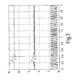
- Figure 3 shows waveforms, which of one in the close range working radar has been added are.
- the upper signal curve is undisturbed.
- the middle one Signal curve is influenced by a strong interference, which in the present case is an example of an FMCW radar is caused.
- the lower signal is through a very strong disturbance influenced by the same type.
- FIG. 4 schematically shows the structure of a sensor 20, which is used in the vicinity of the radar.
- the sensor 20 is an electronic control unit 22 Voltage provided, for example a Voltage of 8 V. This voltage is in a DC-DC converter 24 transformed so that ultimately the supply voltage available for the sensor components is set, for example 5 V.
- a carrier frequency of for example 24 GHz is from a local oscillator 26 delivered.
- This local oscillator 26 is equipped with a Preload, which ultimately comes from the one Clock generator 28 made available by means of pulses a converter 30 is generated.
- the clock generator 28 generated pulses for example a frequency of 5 MHz can be used to modulate the Local oscillator 26 provided carrier signals used.
- This modulation takes place in the transmission branch by the switch 32, which is provided by a pulse shaper 46 is switched.
- the pulse shaper 46 is in turn from the clock frequency of the clock generator 28 driven.
- the Pulsed signals thus generated are generated by the antenna 34 sent out. In the event of a reflection of the signals which are transmitted by the antenna 34, these will received by the receiving antenna 36.
- a first Mixer 40 delivers an I signal while the second mixer 42 outputs a Q signal.
- the switch is from a pulse generator 48 driven, which with respect to the pulses output by the pulse generator 46 by a delay ⁇ t outputs delayed pulses. This delay is available through a delay circuit 50 posed. Via a microcontroller 52, which one digital signal processor has the delay delay circuit 50. this happens via a first analog output 54 of the microcontroller 52. Be through a second analog output 60 the I- or processed by an amplifier 56 respectively Q signals through further variable amplification in the Amplifier 58 affects. Influencing this variable Amplifier 58 takes place by means of a second analog Output 60 of the microcontroller 52. The output signal of variable amplifier 58 becomes an analog Input 62 of the microcontroller 52 supplied. The microcontroller 52 communicates via an input-output bus 64 (I / O bus) with the electronic control unit 22.
- I / O bus input-output bus 64
- the transmission branch of the radar sensor 20 deactivated according to FIG. 4. So there are no transmission signals more transmitted from the transmission antenna 34. Indeed continue to be correlation pulses from the pulse generator 48 given to the receiving branch of the radar sensor 20. provides in this state, in which the transmission branch is switched off is out that destination information is still received a false signal can be inferred from this become. If static target information appears, this can be done through software, for example in the electronic control unit 22 can be eliminated. Deterministically changeable goals can be determined by a another choice of the center frequency of the local oscillator 26 or the pulse repetition frequency, which is from the clock generator 28 is made available to be eliminated.
- a circuit is shown, which largely corresponds to the circuit according to FIG. 4. additionally a notch filter 66 is provided in the receiving branch. This can be used particularly advantageously, if monochromatic or almost monochromatic There are faults.
- the circuit shown in Figure 5 is furthermore in addition to the components according to FIG a PLL circuit 68 and an additional mixer 70 fitted. By tuning this PLL source 68 the interference frequency can be determined means on the basis of the arrangement according to FIG it is no longer necessary to detune the carrier frequency.
- FIG. 6 shows a flow chart to explain a inventive method.
- CFAR constant false alarm rate
- step S05 an attempt is made in step S05 to Eliminate interference. This can be done, for example, by Change in the center frequency, by changing the pulse repetition frequency, through a notch filter or through a Modification scheme is changed.
- the elimination interference signals can also be software-based respectively.
- step S06 it is checked whether the fault was eliminated. If this is the case, normal operation can occur be passed over. Otherwise, in Step S07 invalidates the measurement.
Abstract
Description
- Figur 1
- eine Radareinrichtung des Standes der Technik;
- Figur 2
- ein Kraftfahrzeug mit Radareinrichtungen;
- Figur 3
- Signale mit unterschiedlich starken Störungen;
- Figur 4
- eine Radareinrichtung zur Durchführung der vorliegenden Erfindung;
- Figur 5
- eine weitere Radareinrichtung zur Durchführung der vorliegenden Erfindung; und
- Figur 6
- ein Flussdiagramm zur Erläuterung eines erfindungsgemäßen Verfahrens.
- S01:
- Normalbetrieb.
- S02:
- Unregelmäßigkeiten? Blindheit?
- S03:
- Sender abschalten; gepulster Empfang oder Dauerempfang.
- S04:
- Analyse der Störung.
- S05:
- Versuch, Störung zu eliminieren.
- S06:
- Störung eliminiert?
- S07:
- Messung ungültig.
Claims (18)
- Verfahren zum Erkennen gestörter Zustände einer Radareinrichtung mit den Schritten:Erkennen von Unregelmäßigkeiten beim Empfang von Signalen (S02),Deaktivieren des Sendezweigs (S03) undErkennen der An- oder Abwesenheit von Zielsignalen (S04).
- Verfahren nach Anspruch 1, bei dem im Anschluss an das Erkennen der Anwesenheit von Zielsignalen diese auf Softwarebasis eliminiert werden (S05).
- Verfahren nach Anspruch 1 oder 2, bei dem im Anschluss an das Erkennen der Anwesenheit von Zielsignalen diese durch eine Veränderung der Mittenfrequenz der Radareinrichtung eliminiert werden (S05).
- Verfahren nach einem der vorangehenden Ansprüche, bei dem im Anschluss an das Erkennen der Anwesenheit von Zielsignalen diese durch eine Veränderung der Pulswiederholfrequenz der Radareinrichtung eliminiert werden (S05).
- Verfahren nach einem der vorangehenden Ansprüche, bei dem im Anschluss an das Erkennen der Anwesenheit von Zielsignalen diese durch einen Notchfilter (66) eliminiert werden (S05).
- Verfahren nach einem der vorangehenden Ansprüche, bei dem im Anschluss an das Erkennen der Anwesenheit von Zielsignalen diese durch Pulscodierung eliminiert werden (S05).
- Verfahren nach einem der vorangehenden Ansprüche, bei dem im Anschluss an das Erkennen der An- oder Abwesenheit von Zielsignalenein Dauerträgersignal auf einen Mischer (40, 42) im Empfangszweig gegeben wird (S03) undmittels Verstimmen des Dauerträgersignals die Störfrequenz bestimmt wird (S04).
- Verfahren nach einem der vorangehenden Ansprüche, bei dem im Anschluss an das Erkennen der An- oder Abwesenheit von Zielsignalen mittels Durchstimmen einer PLL-Quelle (68) die Störträgerfrequenz bestimmt wird.
- Verfahren nach einem der vorangehenden Ansprüche, dadurch gekennzeichnet, dass im Falle des Nichteliminierens der Störsignale die Messung als ungültig erklärt wird (S07).
- Radareinrichtung mitMitteln zum Erkennen von Unregelmäßigkeiten beim Empfang von Signalen,Mitteln zum Deaktivieren des Sendezweiges undMitteln zum Erkennen der An- oder Abwesenheit von Zielsignalen.
- Radareinrichtung nach Anspruch 10, bei der im Anschluss an das Erkennen der Anwesenheit von Zielsignalen diese auf Softwarebasis eliminierbar sind.
- Radareinrichtung nach Anspruch 10 oder 11, bei der im Anschluss an das Erkennen der Anwesenheit von Zielsignalen diese durch eine Veränderung der Mittenfrequenz der Radareinrichtung eliminierbar sind (S05).
- Radareinrichtung nach einem der Ansprüche 10 bis 12, bei der im Anschluss an das Erkennen der Anwesenheit von Zielsignalen diese durch eine Veränderung der Pulswiederholfrequenz der Radareinrichtung eliminierbar sind (S05).
- Radareinrichtung nach einem der Ansprüche 10 bis 13, bei der im Anschluss an das Erkennen der Anwesenheit von Zielsignalen diese durch einen Notchfilter (66) eliminierbar sind (S05).
- Radareinrichtung nach einem der Ansprüche 10 bis 14, bei der im Anschluss an das Erkennen der Anwesenheit von Zielsignalen diese durch Pulscodierung eliminierbar sind (S05).
- Radareinrichtung nach einem der Ansprüche 10 bis 15, bei der im Anschluss an das Erkennen der An- oder Abwesenheit von Zielsignalenein Dauerträgersignal auf einen Mischer (40, 42) im Empfangszweig gegeben wird (S03) undmittels Verstimmen des Dauerträgersignals die Störfrequenz bestimmbar ist (S04).
- Radareinrichtung nach einem der Ansprüche 10 bis 16, bei der im Anschluss an das Erkennen der An- oder Abwesenheit von Zielsignalen mittels Durchstimmen einer PLL-Quelle (68) die Störträgerfrequenz bestimmbar ist.
- Radareinrichtung nach einem der Ansprüche 10 bis 17, dadurch gekennzeichnet, dass im Falle des Nichteliminierens der Störsignale die Messung als ungültig erklärt wird (S07).
Applications Claiming Priority (2)
| Application Number | Priority Date | Filing Date | Title |
|---|---|---|---|
| DE10108582 | 2001-02-22 | ||
| DE10108582A DE10108582A1 (de) | 2001-02-22 | 2001-02-22 | Verfahren zum Erkennen gestörter Zustände einer Radareinrichtung und Radareinrichtung |
Publications (2)
| Publication Number | Publication Date |
|---|---|
| EP1235078A2 true EP1235078A2 (de) | 2002-08-28 |
| EP1235078A3 EP1235078A3 (de) | 2003-03-26 |
Family
ID=7675144
Family Applications (1)
| Application Number | Title | Priority Date | Filing Date |
|---|---|---|---|
| EP01129146A Withdrawn EP1235078A3 (de) | 2001-02-22 | 2001-12-08 | Verfahren zum Erkennen gestörter Zustände einer Radareinrichtung und Radareinrichtung |
Country Status (3)
| Country | Link |
|---|---|
| US (1) | US6618003B2 (de) |
| EP (1) | EP1235078A3 (de) |
| DE (1) | DE10108582A1 (de) |
Cited By (2)
| Publication number | Priority date | Publication date | Assignee | Title |
|---|---|---|---|---|
| WO2009153629A1 (en) * | 2008-06-19 | 2009-12-23 | Toyota Jidosha Kabushiki Kaisha | Calibration method with sequential boresight adjustment of multiple automotive radar devices |
| WO2020074417A1 (de) * | 2018-10-11 | 2020-04-16 | Robert Bosch Gmbh | Verfahren zur bestimmung der wertigkeit von radarmesswerten zur bestimmung eines belegungszustands eines stellplatzes |
Families Citing this family (36)
| Publication number | Priority date | Publication date | Assignee | Title |
|---|---|---|---|---|
| DE10142170A1 (de) * | 2001-08-29 | 2003-03-20 | Bosch Gmbh Robert | Pulsradaranordnung |
| US7474705B2 (en) * | 2002-08-16 | 2009-01-06 | Wisair Ltd | Scalable ultra-wide band communication system |
| JP4007498B2 (ja) * | 2002-11-15 | 2007-11-14 | 三菱電機株式会社 | 車載用レーダ装置 |
| DE10254982A1 (de) | 2002-11-26 | 2004-06-03 | Robert Bosch Gmbh | Verfahren und Einrichtung zur adaptiven Leistungsregelung |
| JP2005181193A (ja) * | 2003-12-22 | 2005-07-07 | Tdk Corp | パルス波レーダー装置 |
| DE112006001114T5 (de) * | 2005-05-16 | 2008-04-30 | Murata Manufacturing Co. Ltd. | Radargerät |
| US8238863B2 (en) * | 2009-12-10 | 2012-08-07 | Qualcomm Incorporated | Methods and apparatuses for identifying and mitigating interference in a wireless signal |
| EP2390679B1 (de) * | 2010-05-27 | 2012-10-03 | Mitsubishi Electric R&D Centre Europe B.V. | Automobilradar mit Funkfrequenzstörungsvermeidung |
| US9008249B2 (en) | 2012-02-10 | 2015-04-14 | Qualcomm Incorporated | Detection and filtering of an undesired narrowband signal contribution in a wireless signal receiver |
| US9065686B2 (en) | 2012-11-21 | 2015-06-23 | Qualcomm Incorporated | Spur detection, cancellation and tracking in a wireless signal receiver |
| DE102016202805A1 (de) * | 2016-02-24 | 2017-08-24 | Bayerische Motoren Werke Aktiengesellschaft | Verfahren und Vorrichtung zum Betreiben eines Umfeldsensors eines Fahrzeugs |
| US10261179B2 (en) | 2016-04-07 | 2019-04-16 | Uhnder, Inc. | Software defined automotive radar |
| US9689967B1 (en) | 2016-04-07 | 2017-06-27 | Uhnder, Inc. | Adaptive transmission and interference cancellation for MIMO radar |
| US9846228B2 (en) | 2016-04-07 | 2017-12-19 | Uhnder, Inc. | Software defined automotive radar systems |
| US9791564B1 (en) | 2016-04-25 | 2017-10-17 | Uhnder, Inc. | Adaptive filtering for FMCW interference mitigation in PMCW radar systems |
| US9954955B2 (en) | 2016-04-25 | 2018-04-24 | Uhnder, Inc. | Vehicle radar system with a shared radar and communication system |
| US9945935B2 (en) | 2016-04-25 | 2018-04-17 | Uhnder, Inc. | Digital frequency modulated continuous wave radar using handcrafted constant envelope modulation |
| US9806914B1 (en) | 2016-04-25 | 2017-10-31 | Uhnder, Inc. | Successive signal interference mitigation |
| US9772397B1 (en) | 2016-04-25 | 2017-09-26 | Uhnder, Inc. | PMCW-PMCW interference mitigation |
| US10573959B2 (en) | 2016-04-25 | 2020-02-25 | Uhnder, Inc. | Vehicle radar system using shaped antenna patterns |
| US9791551B1 (en) | 2016-04-25 | 2017-10-17 | Uhnder, Inc. | Vehicular radar system with self-interference cancellation |
| US9753121B1 (en) | 2016-06-20 | 2017-09-05 | Uhnder, Inc. | Power control for improved near-far performance of radar systems |
| WO2018051288A1 (en) | 2016-09-16 | 2018-03-22 | Uhnder, Inc. | Virtual radar configuration for 2d array |
| JP6858523B2 (ja) * | 2016-10-06 | 2021-04-14 | 京セラ株式会社 | 測距装置、測距方法及び車両 |
| US10908272B2 (en) | 2017-02-10 | 2021-02-02 | Uhnder, Inc. | Reduced complexity FFT-based correlation for automotive radar |
| US11454697B2 (en) | 2017-02-10 | 2022-09-27 | Uhnder, Inc. | Increasing performance of a receive pipeline of a radar with memory optimization |
| WO2018146632A1 (en) | 2017-02-10 | 2018-08-16 | Uhnder, Inc. | Radar data buffering |
| JP6881177B2 (ja) * | 2017-09-15 | 2021-06-02 | 株式会社デンソー | レーダ装置 |
| US11105890B2 (en) | 2017-12-14 | 2021-08-31 | Uhnder, Inc. | Frequency modulated signal cancellation in variable power mode for radar applications |
| US11656321B2 (en) * | 2018-07-23 | 2023-05-23 | Richwave Technology Corp. | Method of microwave motion detection with adaptive frequency control and related devices |
| US11474225B2 (en) | 2018-11-09 | 2022-10-18 | Uhnder, Inc. | Pulse digital mimo radar system |
| WO2020183392A1 (en) | 2019-03-12 | 2020-09-17 | Uhnder, Inc. | Method and apparatus for mitigation of low frequency noise in radar systems |
| DE102019214949A1 (de) * | 2019-09-27 | 2021-04-01 | Robert Bosch Gmbh | Verfahren und Vorrichtung zum Erkennen eines absorptiven Radombelags |
| WO2021144711A2 (en) | 2020-01-13 | 2021-07-22 | Uhnder, Inc. | Method and system for intefrence management for digital radars |
| JP2021092585A (ja) * | 2021-02-26 | 2021-06-17 | 住友電気工業株式会社 | 電波センサおよび検知プログラム |
| CN113835077B (zh) * | 2021-11-23 | 2022-02-11 | 中国空气动力研究与发展中心计算空气动力研究所 | 基于变脉冲重复频率的搜索雷达目标检测方法及系统 |
Citations (6)
| Publication number | Priority date | Publication date | Assignee | Title |
|---|---|---|---|---|
| US3115629A (en) * | 1957-03-01 | 1963-12-24 | Marconi Co Ltd | Repetitive signal systems for improving signal to noise ratio |
| US3916406A (en) * | 1963-02-20 | 1975-10-28 | Us Navy | Jamming cancellation device |
| US4901082A (en) * | 1988-11-17 | 1990-02-13 | Grumman Aerospace Corporation | Adaptive waveform radar |
| US5274380A (en) * | 1992-03-17 | 1993-12-28 | Fujitsu Limited | FM-CW radar |
| US6028548A (en) * | 1997-01-17 | 2000-02-22 | Automotive Systems Laboratory, Inc. | Vehicle collision radar with randomized FSK waveform |
| US6141371A (en) * | 1996-12-18 | 2000-10-31 | Raytheon Company | Jamming suppression of spread spectrum antenna/receiver systems |
Family Cites Families (9)
| Publication number | Priority date | Publication date | Assignee | Title |
|---|---|---|---|---|
| FR2278204A1 (fr) * | 1974-07-12 | 1976-02-06 | Thomson Csf | Dispositif integrateur multiple et systeme radar a impulsions a frequences multiples comportant un tel dispositif |
| GB1528164A (en) * | 1975-05-14 | 1978-10-11 | Marconi Co Ltd | Radar |
| US4622555A (en) * | 1982-09-02 | 1986-11-11 | Motorola, Inc. | Coded pulse Doppler radar with clutter-adaptive modulation and method therefore |
| US4717917A (en) * | 1985-06-26 | 1988-01-05 | Rockwell International Corporation | Alien radar suppression circuit |
| GB2270218B (en) * | 1992-07-15 | 1997-03-05 | Futaba Denshi Kogyo Kk | Transmitter for radio control device |
| US5565870A (en) * | 1993-06-28 | 1996-10-15 | Nissan Motor Co., Ltd. | Radar apparatus with determination of presence of target reflections |
| US6148020A (en) * | 1996-03-22 | 2000-11-14 | Sanyo Electric Co., Ltd. | Method and device for frequency hopping communication by changing a carrier frequency |
| US6208248B1 (en) * | 1999-01-28 | 2001-03-27 | Anro Engineering, Inc. | Quick response perimeter intrusion detection sensor |
| US6049302A (en) * | 1999-05-04 | 2000-04-11 | Boeing North American | Pulsed doppler radar system with small intermediate frequency filters |
-
2001
- 2001-02-22 DE DE10108582A patent/DE10108582A1/de not_active Withdrawn
- 2001-12-08 EP EP01129146A patent/EP1235078A3/de not_active Withdrawn
-
2002
- 2002-02-22 US US10/080,651 patent/US6618003B2/en not_active Expired - Fee Related
Patent Citations (6)
| Publication number | Priority date | Publication date | Assignee | Title |
|---|---|---|---|---|
| US3115629A (en) * | 1957-03-01 | 1963-12-24 | Marconi Co Ltd | Repetitive signal systems for improving signal to noise ratio |
| US3916406A (en) * | 1963-02-20 | 1975-10-28 | Us Navy | Jamming cancellation device |
| US4901082A (en) * | 1988-11-17 | 1990-02-13 | Grumman Aerospace Corporation | Adaptive waveform radar |
| US5274380A (en) * | 1992-03-17 | 1993-12-28 | Fujitsu Limited | FM-CW radar |
| US6141371A (en) * | 1996-12-18 | 2000-10-31 | Raytheon Company | Jamming suppression of spread spectrum antenna/receiver systems |
| US6028548A (en) * | 1997-01-17 | 2000-02-22 | Automotive Systems Laboratory, Inc. | Vehicle collision radar with randomized FSK waveform |
Cited By (2)
| Publication number | Priority date | Publication date | Assignee | Title |
|---|---|---|---|---|
| WO2009153629A1 (en) * | 2008-06-19 | 2009-12-23 | Toyota Jidosha Kabushiki Kaisha | Calibration method with sequential boresight adjustment of multiple automotive radar devices |
| WO2020074417A1 (de) * | 2018-10-11 | 2020-04-16 | Robert Bosch Gmbh | Verfahren zur bestimmung der wertigkeit von radarmesswerten zur bestimmung eines belegungszustands eines stellplatzes |
Also Published As
| Publication number | Publication date |
|---|---|
| EP1235078A3 (de) | 2003-03-26 |
| US6618003B2 (en) | 2003-09-09 |
| DE10108582A1 (de) | 2002-09-05 |
| US20020130811A1 (en) | 2002-09-19 |
Similar Documents
| Publication | Publication Date | Title |
|---|---|---|
| EP1235078A2 (de) | Verfahren zum Erkennen gestörter Zustände einer Radareinrichtung und Radareinrichtung | |
| EP1601991B1 (de) | Verfahren und einrichtung zur adaptiven leistungsregelung | |
| DE19744185B4 (de) | Einrichtung zur Abstandsmessung mittels Ultraschall | |
| EP1235079A2 (de) | Verfahren zum Entstören einer Radareinrichtung und Radareinrichtung | |
| DE102013218571A1 (de) | Vorrichtung und Verfahren zur seitlichen Umfelderfassung eines Kraftfahrzeugs | |
| EP0269902B1 (de) | Verfahren und Einrichtung zum Bestimmen der Entfernung zwischen zwei Objekten, insbesondere zwei Kraftfahrzeugen | |
| DE102013211846A1 (de) | Verfahren zum Betrieb eines Umfelderfassungssystems eines Fahrzeugs | |
| DE19924755A1 (de) | Abstandserfassungsvorrichtung | |
| EP1210567A1 (de) | Vorrichtung zur bestimmung einer physikalischen prozessgrösse eines mediums | |
| DE102012202975A1 (de) | Verfahren zur Umfelderkennung sowie Fahrassistenzsystem | |
| DE10258097A1 (de) | Einrichtung zur Abstands- und Geschwindigkeitsmessung von Objekten | |
| EP1481260A1 (de) | PULSRADARVORRICHTUNG UND VERFAHREN ZUM ERFASSEN, ZUM DETEKTIEREN UND/ODER ZUM AUSWERTEN VON MINDESTENS EINEM OBJEKT | |
| DE10249866B4 (de) | Vorrichtung zur Positionsbestimmung wenigstens einer zweiten Sende- und Empfangseinrichtung bezüglich einer ersten Sende- und Empfangseinrichtung in einem GHz-Bereich arbeitenden passiven Zugangskontrollsystem | |
| WO2016050629A1 (de) | Radarsensor | |
| DE102010040890A1 (de) | Radarsensor mit phasengeregeltem Oszillator | |
| EP0919834A1 (de) | Verfahren zur Detektion eines Zieles mittels einer HPRF-Radaranlage | |
| DE19754220A1 (de) | Verfahren und Vorrichtung zur Erkennung einer bevorstehenden oder möglichen Kollision | |
| EP1636069B1 (de) | Vorrichtung zur ansteuerung von r ckhaltemitteln | |
| EP3199975A1 (de) | Radarbasierter näherungssensor | |
| DE10342128A1 (de) | Verfahren und Abstandserfassungsvorrichtung zum Bestimmen des Abstandes zwischen mindestens einer Sensoreinrichtung und einem Objekt | |
| EP1516200B1 (de) | Verfahren und vorrichtung zum erzeugen von hf-signalen zum bestimmen eines abstandes und/oder einer geschwindigkeit eines objektes | |
| EP1449008B1 (de) | Fmcw-radar mit begrenzung der sendezeit zur vermeidung von aliasing-effekten | |
| EP3018490B1 (de) | Verfahren zur detektion einer interferenz in einem empfangssignal eines radarsensors eines kraftfahrzeugs, recheneinrichtung, fahrerassistenzsystem, kraftfahrzeug sowie computerprogrammprodukt | |
| DE102017102592A1 (de) | Verfahren zum Betreiben eines Radarsensors eines Kraftfahrzeugs mit Speicherung eines Filterkoeffizienten, Radarsensor, Fahrerassistenzsystem sowie Kraftfahrzeug | |
| EP4058822A1 (de) | Verfahren zum betreiben eines abstandssensors eines fahrzeugs mit anpassung eines sendesignals in abhängigkeit von einer klassifizierung eines objekts, recheneinrichtung sowie sensorvorrichtung |
Legal Events
| Date | Code | Title | Description |
|---|---|---|---|
| PUAI | Public reference made under article 153(3) epc to a published international application that has entered the european phase |
Free format text: ORIGINAL CODE: 0009012 |
|
| AK | Designated contracting states |
Kind code of ref document: A2 Designated state(s): AT BE CH CY DE DK ES FI FR GB GR IE IT LI LU MC NL PT SE TR |
|
| AX | Request for extension of the european patent |
Free format text: AL;LT;LV;MK;RO;SI |
|
| PUAL | Search report despatched |
Free format text: ORIGINAL CODE: 0009013 |
|
| AK | Designated contracting states |
Kind code of ref document: A3 Designated state(s): AT BE CH CY DE DK ES FI FR GB GR IE IT LI LU MC NL PT SE TR Designated state(s): AT BE CH CY DE DK ES FI FR GB GR IE IT LI LU MC NL PT SE TR |
|
| AX | Request for extension of the european patent |
Extension state: AL LT LV MK RO SI |
|
| RIC1 | Information provided on ipc code assigned before grant |
Ipc: 7G 01S 7/36 B Ipc: 7G 01S 7/40 A |
|
| AKX | Designation fees paid | ||
| REG | Reference to a national code |
Ref country code: DE Ref legal event code: 8566 |
|
| STAA | Information on the status of an ep patent application or granted ep patent |
Free format text: STATUS: THE APPLICATION IS DEEMED TO BE WITHDRAWN |
|
| 18D | Application deemed to be withdrawn |
Effective date: 20030929 |