EP1234982A1 - Vacuum pump - Google Patents
Vacuum pump Download PDFInfo
- Publication number
- EP1234982A1 EP1234982A1 EP01830121A EP01830121A EP1234982A1 EP 1234982 A1 EP1234982 A1 EP 1234982A1 EP 01830121 A EP01830121 A EP 01830121A EP 01830121 A EP01830121 A EP 01830121A EP 1234982 A1 EP1234982 A1 EP 1234982A1
- Authority
- EP
- European Patent Office
- Prior art keywords
- pumping
- pump
- vacuum pump
- pumping section
- rotor
- Prior art date
- Legal status (The legal status is an assumption and is not a legal conclusion. Google has not performed a legal analysis and makes no representation as to the accuracy of the status listed.)
- Granted
Links
- 238000005086 pumping Methods 0.000 claims abstract description 63
- XLYOFNOQVPJJNP-UHFFFAOYSA-N water Substances O XLYOFNOQVPJJNP-UHFFFAOYSA-N 0.000 claims description 7
- 238000001816 cooling Methods 0.000 claims description 5
- 239000007789 gas Substances 0.000 description 7
- 239000012530 fluid Substances 0.000 description 3
- 238000010521 absorption reaction Methods 0.000 description 2
- 239000000498 cooling water Substances 0.000 description 2
- 238000012423 maintenance Methods 0.000 description 2
- 230000006835 compression Effects 0.000 description 1
- 238000007906 compression Methods 0.000 description 1
- 230000008878 coupling Effects 0.000 description 1
- 238000010168 coupling process Methods 0.000 description 1
- 238000005859 coupling reaction Methods 0.000 description 1
- 230000007423 decrease Effects 0.000 description 1
- 230000000694 effects Effects 0.000 description 1
- 239000007788 liquid Substances 0.000 description 1
- 239000000314 lubricant Substances 0.000 description 1
- 238000005461 lubrication Methods 0.000 description 1
- 238000000034 method Methods 0.000 description 1
- 230000000750 progressive effect Effects 0.000 description 1
- 239000004065 semiconductor Substances 0.000 description 1
Images


Classifications
-
- F—MECHANICAL ENGINEERING; LIGHTING; HEATING; WEAPONS; BLASTING
- F04—POSITIVE - DISPLACEMENT MACHINES FOR LIQUIDS; PUMPS FOR LIQUIDS OR ELASTIC FLUIDS
- F04D—NON-POSITIVE-DISPLACEMENT PUMPS
- F04D25/00—Pumping installations or systems
- F04D25/16—Combinations of two or more pumps ; Producing two or more separate gas flows
-
- F—MECHANICAL ENGINEERING; LIGHTING; HEATING; WEAPONS; BLASTING
- F04—POSITIVE - DISPLACEMENT MACHINES FOR LIQUIDS; PUMPS FOR LIQUIDS OR ELASTIC FLUIDS
- F04D—NON-POSITIVE-DISPLACEMENT PUMPS
- F04D19/00—Axial-flow pumps
- F04D19/02—Multi-stage pumps
- F04D19/04—Multi-stage pumps specially adapted to the production of a high vacuum, e.g. molecular pumps
- F04D19/046—Combinations of two or more different types of pumps
-
- F—MECHANICAL ENGINEERING; LIGHTING; HEATING; WEAPONS; BLASTING
- F04—POSITIVE - DISPLACEMENT MACHINES FOR LIQUIDS; PUMPS FOR LIQUIDS OR ELASTIC FLUIDS
- F04F—PUMPING OF FLUID BY DIRECT CONTACT OF ANOTHER FLUID OR BY USING INERTIA OF FLUID TO BE PUMPED; SIPHONS
- F04F5/00—Jet pumps, i.e. devices in which flow is induced by pressure drop caused by velocity of another fluid flow
- F04F5/02—Jet pumps, i.e. devices in which flow is induced by pressure drop caused by velocity of another fluid flow the inducing fluid being liquid
- F04F5/04—Jet pumps, i.e. devices in which flow is induced by pressure drop caused by velocity of another fluid flow the inducing fluid being liquid displacing elastic fluids
Landscapes
- Engineering & Computer Science (AREA)
- Mechanical Engineering (AREA)
- General Engineering & Computer Science (AREA)
- Physics & Mathematics (AREA)
- Fluid Mechanics (AREA)
- Non-Positive Displacement Air Blowers (AREA)
- Structures Of Non-Positive Displacement Pumps (AREA)
Abstract
Description
- The present invention relates to an improved vacuum pump.
- More particularly, the invention relates to a turbomolecular vacuum pump with a particularly high compression ratio, capable of exhausting at atmospheric pressure.
- Turbomolecular pumps are known which comprise pumping stages with plane or bladed rotors, see for instance EP-B 445 855 in the name of the same Applicant.
- Conventional turbomolecular pumps have rather limited operation ranges, that is, they cannot reach a pressure difference, between the inlet and outlet ducts, such as to allow exhaust at atmospheric pressure. Even if considerable advances have been made in recent years, resulting in the development of turbomolecular pumps allowing exhaust at higher and higher pressures, providing a so-called fore pump coupled with the turbomolecular pump is at present still necessary.
- Fore pumps are coupled outside the turbomolecular pump and therefore they require connection thereto through gas flow ducts, and electrical supply by the same control unit as that supplying the turbomolecular pump. All this makes the pumping system complex and more subject to failures.
- A vacuum generating system, comprising a molecular pump coupled with a fore pump, is disclosed in EP-A 256 234. According to that document, the exhaust port of a molecular rotary pump, comprising a plurality of pumping stages defined by the coupling of a rotor and a stator, is directly connected with a suction duct of a screw pump. The discharge port of the screw pump exhausts at atmospheric pressure.
- The structural complexity of such a system is immediately apparent. Actually the system needs two separate electric motors, since the pumps are to rotate at very different speeds. Moreover, even if the fore pump is equipped with a seal assembly arranged to prevent lubricant from entering the pumping chamber, and hence the molecular pump, pollution is always possible, for instance in case of failures or poor maintenance.
- Ejector or venturi pumps are also known which are actuated by a first, high-pressure fluid and suck a second, low-pressure fluid thereby generating an intermediate pressure level at the outlet. Both the first and the second fluid can indiscriminately be either a liquid or a gas: for instance, by feeding the pump with pressurised water, it is possible to suck a gas such as air, thereby generating a low pressure in a closed space and creating a fore vacuum condition.
- Ejector or venturi pumps, of a kind suitable for sucking a gas, generally can work starting from pressures of about 30 millibars.
- It is an object of the invention to provide a turbomolecular pump capable of exhausting at atmospheric pressure.
- This object is achieved through a turbomolecular vacuum pump comprising, starting from the inlet port, a first pumping section having pumping stages with bladed rotor discs, a second pumping section having pumping stages with smooth rotor discs, a third pumping section having at least one pumping stage with toothed rotor disc, and a fourth ejector or venturi pumping section.
- Advantageously, according to the invention, optimised progressive pumping stages are provided in the turbomolecular pump, capable of bringing the exhaust pressure of the turbomolecular pump to a level suitable for the operation of an ejector or venturi pump, typically 30 mbar.
- According to the invention, the turbomolecular pump is capable of exhausting at a pressure of about 100 mbar already at the third stage.
- Surprisingly moreover, by using a vacuum pump made in accordance with the invention, in particular with a third pumping stage having a rotor disc with straight teeth, an energy saving can be achieved. Indeed, at the exhaust pressure of 30 mbars it has been experienced that the pump having a pumping stage with toothed rotor has lower electric current absorption than a pump not equipped with a stage with toothed rotor disc.
- The above and other objects are achieved by the vacuum pump made in accordance with to the invention, as claimed in the appended claims.
- Advantageously, the vacuum pump according to the invention can be used in all applications where a high vacuum condition is required in particularly clean environments, such as for instance in semiconductor working processes.
- The above and other objects of the invention will become more apparent from the description of a preferred embodiment, with reference to the accompanying drawings, in which:
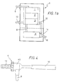
- Fig. 1a is a schematical view of a turbomolecular vacuum pump made in accordance with a first embodiment of the present invention;
- Fig. 1b is a schematical view of a turbomolecular vacuum pump made in accordance with a second embodiment of the present invention;
- Fig. 2 is a cross sectional view of a pumping rotor of a turbomolecular vacuum pump made in accordance with the present invention;
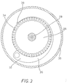
- Fig. 3 is a plan view of a particular pumping stage of a turbomolecular vacuum pump made in accordance with the present invention; and
- Fig. 4 is a side view of an ejector or venturi pumping section of a vacuum pump made in accordance with the present invention.
- Referring to Fig. 1a, a
vacuum pump 5, according to a first exemplary embodiment, comprises fourdifferent pumping sections suction duct 6 and anexhaust duct 16. The first three sections are part of a turbomolecular pump, comprising arotor 20, shown in detail in Fig. 2, and equipped with a plurality of pumping stages defined byrotor discs 22a - 22h, 24a - 24f and 26, coupled with stator rings, not shown in Fig. 2. - Fig. 2 shows, in cross sectional view, the structure of
rotor 20 of the turbomolecular pumping section. Thefirst pumping group 1, including eightrotor discs 22a - 22h with inclined blades, is provided on the pump side proximal tosuction duct 6. The blade inclination progressively increases from thefirst rotor disc 22a to thelast rotor disc 22h. Indeed, the blades of thefirst rotor disc 22a are inclined of about 45° relative to the rotational axis of the rotor, whereas the blades of thelast rotor disc 22h are almost horizontal. - A
second pumping group 2, axially aligned with the first pumping group and comprising six smooth rotor discs 24a - 24f, is located below the first pumping stage. The first two smooth rotor discs 24a and 24b have the same diameter as the preceding bladed rotor discs, whereas the last four smooth rotor discs 24c - 24f have smaller diameter. - A
third pumping group 3 comprises arotor disc 26 with straight teeth and is coupled with astator ring 30.Rotor 20 further comprises arotation shaft 28, integral with the rotor discs and driven by a suitable electric motor. - The
third pumping group 3 is shown in detail in Fig. 3.Rotor disc 26, equipped with a plurality ofstraight teeth 34, is spaced fromstator ring 30 so as to form, between the side surface ofrotor disc 26 and the inner circumferential surface ofstator ring 30, a free and taperedannular channel 36. - Tapered
channel 36 has a suction port and a discharge port located at opposite ends ofchannel 36 and defining agas suction region 32 and agas discharge region 38, respectively. A tapered groove instator ring 30forms channel 36 linearly tapered fromsuction region 32 towardsdischarge region 38. The transverse size ofchannel 36 progressively decreases from the suction port towards the discharge port, in counterclockwise direction, in circumferential direction aboutrotor disc 26. - Thanks to
rotor 26 with straight teeth and to taperedchannel 36, already the third pumping section is capable of exhausting at a pressure of about 100 mbar. However even if such pressure is very high, it does not yet allow a direct connection with the outside environment (i.e. the environment at atmospheric pressure). -
Discharge region 38 of the third pumping section is thus connected, through anintermediate duct 8, visible in the diagrammatic overall view ofvacuum pump 5 shown in Fig. 1a, to a fourth ejector orventuri pumping section 4. The fourth pumping section is fed, through aduct 14, by coolingwater circuit 12 of the preceding turbomolecular pumping sections. Indeed, the pressurised cooling water enterspump 5 through aninlet duct 10, passes intocooling circuit 12 ofturbomolecular sections duct 14, the fourth ejector pumping section, shown in detail in Fig. 4. - In the alternative, the fourth pumping section could be fed through a suitable hydraulic circuit, as in the exemplary embodiment shown in Fig. 1b in which the cooling circuit of
stages ejector pump 4. - Fig. 1b actually shows a vacuum pump in which the ejector or
venturi pumping section 4 is fed by an independent external hydraulic circuit. -
Ejector pumping section 4, shown in detail in Fig. 4, comprises aninlet 14 for pressurised water, asuction duct 8 connected to the outlet of thethird pumping section 3, and anexhaust duct 16 from which driving water and sucked gases are exhausted in admixture, at atmospheric pressure. - Water passage in the ejector or venturi pump actually creates a vacuum in
suction duct 8 allowing the pump to exhaust at atmospheric pressure. - The
fourth pumping section 4, having neither moving parts nor electrically powered parts, has a number of advantages. It is not easily subject to failures, it does not require special maintenance and lubrication and does not consume electric power, exploiting the pressurised water coming from the cooling circuit of the turbomolecular sections. Moreover, thanks to its structural simplicity, it scarcely adds to the overall cost of the vacuum pump. - The absence of lubricated parts in that
latter section 4 moreover reduces the possibility of polluting the environment where vacuum is generated. - The operation principle and the internal structure of an ejector or venturi pump, having inlet and outlet ducts with convergent and divergent cross sections, respectively, are known to those of average skill in the art. Those pumps are in effect included in different models and sizes in the catalogues, depending on the features and the required use.
- The reduced power consumption of the pump, obtained through the use of an ejector pump as the fourth pumping section, is moreover favoured by the presence of the third pumping stage including a rotor disc with straight teeth. Indeed, at the exhaust pressure of 30 mbar it has been experienced that the pump with a toothed pumping stage has lower electric current absorption than a pump not equipped with a stage with toothed rotor disc.
Claims (8)
- A vacuum pump (5) comprising a plurality of pumping sections arranged between a suction duct (6) and an exhaust duct (16) and including at least one turbomolecular pumping section (1, 2, 3), characterised in that said pump comprises a pumping section (4) of the ejector or venturi pump type.
- A vacuum pump (5) as claimed in claim 1, comprising a first pumping section (1) having pumping stages with bladed rotor discs (22a - 22h), a second pumping section (2) having pumping stages with smooth rotor discs (24a - 24f), a third pumping section (3) having at least one pumping stage with toothed rotor disc, and a fourth pumping section consisting of said pumping section (4) of the ejector or venturi pump type.
- A vacuum pump (5) as claimed in claim 1 or 2, wherein said ejector pumping section (4) comprises a water-actuated venturi pump.
- A vacuum pump (5) as claimed in claim 3 when appended to claim 2, wherein said venturi pump includes an inlet duct (14) for pressurised water, a suction duct (8) connected with a discharge port of said third pumping section (3), and a discharge duct connected with said exhaust duct (16).
- A vacuum pump (5) as claimed in claim 3, wherein said venturi pump is fed with water from a cooling circuit (12) of said at least one turbomolecular pumping section.
- A vacuum pump (5) as claimed in claim 2, wherein said pumping stage with toothed rotor disc comprises a rotor (26) with straight teeth (34).
- A vacuum pump (5) as claimed in claim 6, wherein said rotor (26) with straight teeth is coupled with a stator ring (30) and wherein a tapered free channel (36) is defined between said rotor (26) and said stator ring (30).
- A vacuum pump (5) as claimed in any preceding claim, wherein said pumping sections (1, 2, 3, 4) form a single body.
Priority Applications (2)
| Application Number | Priority Date | Filing Date | Title |
|---|---|---|---|
| EP20010830121 EP1234982B1 (en) | 2001-02-22 | 2001-02-22 | Vacuum pump |
| DE2001601368 DE60101368T2 (en) | 2001-02-22 | 2001-02-22 | vacuum pump |
Applications Claiming Priority (1)
| Application Number | Priority Date | Filing Date | Title |
|---|---|---|---|
| EP20010830121 EP1234982B1 (en) | 2001-02-22 | 2001-02-22 | Vacuum pump |
Publications (2)
| Publication Number | Publication Date |
|---|---|
| EP1234982A1 true EP1234982A1 (en) | 2002-08-28 |
| EP1234982B1 EP1234982B1 (en) | 2003-12-03 |
Family
ID=8184417
Family Applications (1)
| Application Number | Title | Priority Date | Filing Date |
|---|---|---|---|
| EP20010830121 Expired - Lifetime EP1234982B1 (en) | 2001-02-22 | 2001-02-22 | Vacuum pump |
Country Status (2)
| Country | Link |
|---|---|
| EP (1) | EP1234982B1 (en) |
| DE (1) | DE60101368T2 (en) |
Cited By (8)
| Publication number | Priority date | Publication date | Assignee | Title |
|---|---|---|---|---|
| WO2004055376A2 (en) * | 2002-12-17 | 2004-07-01 | The Boc Group Plc | Vacuum pumping arrangement |
| WO2004055377A1 (en) | 2002-12-17 | 2004-07-01 | The Boc Group Plc | Vacuum pumping system and method of operating a vacuum pumping arrangement |
| WO2004055378A1 (en) * | 2002-12-17 | 2004-07-01 | The Boc Group Plc | Vacuum pumping arrangement and method of operating same |
| WO2005033522A1 (en) * | 2003-09-30 | 2005-04-14 | The Boc Group Plc | Vacuum pump |
| EP1609990A1 (en) * | 2003-03-03 | 2005-12-28 | OHMI, Tadahiro | Vacuum device and vacuum pump |
| US7452191B2 (en) * | 2002-05-03 | 2008-11-18 | Piab Ab | Vacuum pump and method for generating sub-pressure |
| FR2952683A1 (en) * | 2009-11-18 | 2011-05-20 | Alcatel Lucent | METHOD AND APPARATUS FOR PUMPING WITH REDUCED ENERGY CONSUMPTION |
| WO2014072276A1 (en) * | 2012-11-09 | 2014-05-15 | Oerlikon Leybold Vacuum Gmbh | Vacuum pump system for evacuating a chamber, and method for controlling a vacuum pump system |
Families Citing this family (2)
| Publication number | Priority date | Publication date | Assignee | Title |
|---|---|---|---|---|
| DE102006043327A1 (en) * | 2006-09-15 | 2008-03-27 | Oerlikon Leybold Vacuum Gmbh | vacuum pump |
| EP3267040B1 (en) | 2016-07-04 | 2023-12-20 | Pfeiffer Vacuum Gmbh | Turbomolecular pump |
Citations (4)
| Publication number | Priority date | Publication date | Assignee | Title |
|---|---|---|---|---|
| EP0256234A2 (en) | 1986-06-12 | 1988-02-24 | Hitachi, Ltd. | Vacuum generating system |
| EP0340685A2 (en) * | 1988-04-30 | 1989-11-08 | Nippon Ferrofluidics Corporation | Composite vacuum pump |
| EP0445855A1 (en) * | 1990-03-09 | 1991-09-11 | VARIAN S.p.A. | Improved turbomolecular pump |
| US5118251A (en) * | 1989-12-28 | 1992-06-02 | Alcatel Cit | Compound turbomolecular vacuum pump having two rotary shafts and delivering to atmospheric pressure |
-
2001
- 2001-02-22 EP EP20010830121 patent/EP1234982B1/en not_active Expired - Lifetime
- 2001-02-22 DE DE2001601368 patent/DE60101368T2/en not_active Expired - Lifetime
Patent Citations (6)
| Publication number | Priority date | Publication date | Assignee | Title |
|---|---|---|---|---|
| EP0256234A2 (en) | 1986-06-12 | 1988-02-24 | Hitachi, Ltd. | Vacuum generating system |
| US4797068A (en) * | 1986-06-12 | 1989-01-10 | Hitachi, Ltd. | Vacuum evacuation system |
| EP0340685A2 (en) * | 1988-04-30 | 1989-11-08 | Nippon Ferrofluidics Corporation | Composite vacuum pump |
| US5118251A (en) * | 1989-12-28 | 1992-06-02 | Alcatel Cit | Compound turbomolecular vacuum pump having two rotary shafts and delivering to atmospheric pressure |
| EP0445855A1 (en) * | 1990-03-09 | 1991-09-11 | VARIAN S.p.A. | Improved turbomolecular pump |
| EP0445855B1 (en) | 1990-03-09 | 1994-10-26 | VARIAN S.p.A. | Improved turbomolecular pump |
Cited By (20)
| Publication number | Priority date | Publication date | Assignee | Title |
|---|---|---|---|---|
| US7452191B2 (en) * | 2002-05-03 | 2008-11-18 | Piab Ab | Vacuum pump and method for generating sub-pressure |
| WO2004055377A1 (en) | 2002-12-17 | 2004-07-01 | The Boc Group Plc | Vacuum pumping system and method of operating a vacuum pumping arrangement |
| WO2004055378A1 (en) * | 2002-12-17 | 2004-07-01 | The Boc Group Plc | Vacuum pumping arrangement and method of operating same |
| WO2004055376A3 (en) * | 2002-12-17 | 2004-08-05 | Boc Group Plc | Vacuum pumping arrangement |
| US7896625B2 (en) | 2002-12-17 | 2011-03-01 | Edwards Limited | Vacuum pumping system and method of operating a vacuum pumping arrangement |
| JP2006509955A (en) * | 2002-12-17 | 2006-03-23 | ザ ビーオーシー グループ ピーエルシー | Vacuum pump discharge system and method of operating vacuum pump discharge device |
| WO2004055376A2 (en) * | 2002-12-17 | 2004-07-01 | The Boc Group Plc | Vacuum pumping arrangement |
| EP1609990A1 (en) * | 2003-03-03 | 2005-12-28 | OHMI, Tadahiro | Vacuum device and vacuum pump |
| EP1609990A4 (en) * | 2003-03-03 | 2007-07-18 | Tadahiro Ohmi | Vacuum device and vacuum pump |
| US7762763B2 (en) | 2003-09-30 | 2010-07-27 | Edwards Limited | Vacuum pump |
| CN100429406C (en) * | 2003-09-30 | 2008-10-29 | 爱德华兹有限公司 | Vacuum pump |
| WO2005033522A1 (en) * | 2003-09-30 | 2005-04-14 | The Boc Group Plc | Vacuum pump |
| FR2952683A1 (en) * | 2009-11-18 | 2011-05-20 | Alcatel Lucent | METHOD AND APPARATUS FOR PUMPING WITH REDUCED ENERGY CONSUMPTION |
| WO2011061429A3 (en) * | 2009-11-18 | 2012-07-12 | Adixen Vacuum Products | Method and device for pumping with reduced power use |
| CN102713299A (en) * | 2009-11-18 | 2012-10-03 | 阿迪克森真空产品公司 | Pumping method and apparatus with low power consumption |
| US9175688B2 (en) | 2009-11-18 | 2015-11-03 | Adixen Vacuum Products | Vacuum pumping system having an ejector and check valve |
| CN102713299B (en) * | 2009-11-18 | 2016-04-27 | 阿迪克森真空产品公司 | There is pumping method and the equipment of low power consumption |
| WO2014072276A1 (en) * | 2012-11-09 | 2014-05-15 | Oerlikon Leybold Vacuum Gmbh | Vacuum pump system for evacuating a chamber, and method for controlling a vacuum pump system |
| CN104822943A (en) * | 2012-11-09 | 2015-08-05 | 厄利孔莱博尔德真空技术有限责任公司 | Vacuum pump system for evacuating chamber, and method for controlling vacuum pump system |
| CN104822943B (en) * | 2012-11-09 | 2016-12-21 | 厄利孔莱博尔德真空技术有限责任公司 | For to the vacuum pump system of chamber evacuation and for the method controlling vacuum pump system |
Also Published As
| Publication number | Publication date |
|---|---|
| DE60101368D1 (en) | 2004-01-15 |
| DE60101368T2 (en) | 2004-10-14 |
| EP1234982B1 (en) | 2003-12-03 |
Similar Documents
| Publication | Publication Date | Title |
|---|---|---|
| US4797068A (en) | Vacuum evacuation system | |
| KR100843328B1 (en) | Operation Method for Evacuating Apparatus | |
| US4668160A (en) | Vacuum pump | |
| EP1126179A3 (en) | Multi stage electrical air pump | |
| EP1234982B1 (en) | Vacuum pump | |
| KR19990075384A (en) | Compact Turbo Compressor | |
| CN100590317C (en) | Single stage turbine vacuum pumping machine and method for pumping vacuum by the machine | |
| JP2001027195A (en) | Vacuum pump | |
| US6672828B2 (en) | Vacuum pump | |
| EP1108145B1 (en) | Self-propelled vacuum pump | |
| JPH04136497A (en) | Turbo vacuum pump | |
| JPS60252197A (en) | Vacuum pump | |
| JP2001090690A (en) | Vacuum pump | |
| USRE33129E (en) | Vacuum pump | |
| KR100339550B1 (en) | Diffuser for turbo compressor | |
| KR20060084060A (en) | Turbo compressor | |
| KR20010010869A (en) | Sealing device for turbo compressor | |
| JPH02264196A (en) | Turbine vacuum pump | |
| JPS6385286A (en) | Vacuum pump | |
| KR100339545B1 (en) | Turbo compressor | |
| KR20000003085A (en) | Gap leakage reduction structure of turbo compressor | |
| KR100453129B1 (en) | Suction structure of small turbo compressor, for preventing backflow of refrigerant gas by forming step at impeller contact portion of shroud | |
| KR20040021333A (en) | The multi-stage fan of a vacuum cleaner | |
| JPH09195935A (en) | Air compressor | |
| JPH04209993A (en) | Centrifugal compressor |
Legal Events
| Date | Code | Title | Description |
|---|---|---|---|
| PUAI | Public reference made under article 153(3) epc to a published international application that has entered the european phase |
Free format text: ORIGINAL CODE: 0009012 |
|
| AK | Designated contracting states |
Kind code of ref document: A1 Designated state(s): AT BE CH CY DE DK ES FI FR GB GR IE IT LI LU MC NL PT SE TR |
|
| AX | Request for extension of the european patent |
Free format text: AL;LT;LV;MK;RO;SI |
|
| 17P | Request for examination filed |
Effective date: 20021114 |
|
| GRAH | Despatch of communication of intention to grant a patent |
Free format text: ORIGINAL CODE: EPIDOS IGRA |
|
| GRAH | Despatch of communication of intention to grant a patent |
Free format text: ORIGINAL CODE: EPIDOS IGRA |
|
| AKX | Designation fees paid |
Designated state(s): DE FR GB IT |
|
| GRAA | (expected) grant |
Free format text: ORIGINAL CODE: 0009210 |
|
| AK | Designated contracting states |
Kind code of ref document: B1 Designated state(s): DE FR GB IT |
|
| REG | Reference to a national code |
Ref country code: GB Ref legal event code: FG4D |
|
| REG | Reference to a national code |
Ref country code: IE Ref legal event code: FG4D |
|
| REF | Corresponds to: |
Ref document number: 60101368 Country of ref document: DE Date of ref document: 20040115 Kind code of ref document: P |
|
| ET | Fr: translation filed | ||
| PLBE | No opposition filed within time limit |
Free format text: ORIGINAL CODE: 0009261 |
|
| STAA | Information on the status of an ep patent application or granted ep patent |
Free format text: STATUS: NO OPPOSITION FILED WITHIN TIME LIMIT |
|
| REG | Reference to a national code |
Ref country code: IE Ref legal event code: MM4A |
|
| 26N | No opposition filed |
Effective date: 20040906 |
|
| PG25 | Lapsed in a contracting state [announced via postgrant information from national office to epo] |
Ref country code: IT Free format text: LAPSE BECAUSE OF NON-PAYMENT OF DUE FEES Effective date: 20050222 |
|
| PGRI | Patent reinstated in contracting state [announced from national office to epo] |
Ref country code: IT Effective date: 20091201 |
|
| PGFP | Annual fee paid to national office [announced via postgrant information from national office to epo] |
Ref country code: FR Payment date: 20100303 Year of fee payment: 10 Ref country code: IT Payment date: 20100223 Year of fee payment: 10 |
|
| PGFP | Annual fee paid to national office [announced via postgrant information from national office to epo] |
Ref country code: GB Payment date: 20100224 Year of fee payment: 10 Ref country code: DE Payment date: 20100226 Year of fee payment: 10 |
|
| GBPC | Gb: european patent ceased through non-payment of renewal fee |
Effective date: 20110222 |
|
| REG | Reference to a national code |
Ref country code: FR Ref legal event code: ST Effective date: 20111102 |
|
| PG25 | Lapsed in a contracting state [announced via postgrant information from national office to epo] |
Ref country code: IT Free format text: LAPSE BECAUSE OF NON-PAYMENT OF DUE FEES Effective date: 20110222 |
|
| PG25 | Lapsed in a contracting state [announced via postgrant information from national office to epo] |
Ref country code: FR Free format text: LAPSE BECAUSE OF NON-PAYMENT OF DUE FEES Effective date: 20110228 |
|
| REG | Reference to a national code |
Ref country code: DE Ref legal event code: R119 Ref document number: 60101368 Country of ref document: DE Effective date: 20110901 |
|
| PG25 | Lapsed in a contracting state [announced via postgrant information from national office to epo] |
Ref country code: GB Free format text: LAPSE BECAUSE OF NON-PAYMENT OF DUE FEES Effective date: 20110222 |
|
| PG25 | Lapsed in a contracting state [announced via postgrant information from national office to epo] |
Ref country code: DE Free format text: LAPSE BECAUSE OF NON-PAYMENT OF DUE FEES Effective date: 20110901 |