EP1233465B1 - Stromkollektorplatte mit asymmetrischem, von einem gemeinsamen Brennpunkt ausgehenden Rippenmuster - Google Patents
Stromkollektorplatte mit asymmetrischem, von einem gemeinsamen Brennpunkt ausgehenden Rippenmuster Download PDFInfo
- Publication number
- EP1233465B1 EP1233465B1 EP02251050A EP02251050A EP1233465B1 EP 1233465 B1 EP1233465 B1 EP 1233465B1 EP 02251050 A EP02251050 A EP 02251050A EP 02251050 A EP02251050 A EP 02251050A EP 1233465 B1 EP1233465 B1 EP 1233465B1
- Authority
- EP
- European Patent Office
- Prior art keywords
- conductors
- concentric
- frame
- group
- current collector
- Prior art date
- Legal status (The legal status is an assumption and is not a legal conclusion. Google has not performed a legal analysis and makes no representation as to the accuracy of the status listed.)
- Expired - Lifetime
Links
- 239000004020 conductor Substances 0.000 claims abstract description 150
- PXHVJJICTQNCMI-UHFFFAOYSA-N Nickel Chemical compound [Ni] PXHVJJICTQNCMI-UHFFFAOYSA-N 0.000 claims description 8
- 238000000034 method Methods 0.000 claims description 5
- 239000007772 electrode material Substances 0.000 claims description 4
- 239000003792 electrolyte Substances 0.000 claims description 4
- 229910052759 nickel Inorganic materials 0.000 claims description 4
- RTAQQCXQSZGOHL-UHFFFAOYSA-N Titanium Chemical compound [Ti] RTAQQCXQSZGOHL-UHFFFAOYSA-N 0.000 claims description 3
- 229910052782 aluminium Inorganic materials 0.000 claims description 3
- XAGFODPZIPBFFR-UHFFFAOYSA-N aluminium Chemical compound [Al] XAGFODPZIPBFFR-UHFFFAOYSA-N 0.000 claims description 3
- 239000010935 stainless steel Substances 0.000 claims description 3
- 229910001220 stainless steel Inorganic materials 0.000 claims description 3
- 239000010936 titanium Substances 0.000 claims description 3
- 229910052719 titanium Inorganic materials 0.000 claims description 3
- RYGMFSIKBFXOCR-UHFFFAOYSA-N Copper Chemical compound [Cu] RYGMFSIKBFXOCR-UHFFFAOYSA-N 0.000 claims description 2
- 230000003213 activating effect Effects 0.000 claims description 2
- 229910045601 alloy Inorganic materials 0.000 claims description 2
- 239000000956 alloy Substances 0.000 claims description 2
- 229910017052 cobalt Inorganic materials 0.000 claims description 2
- 239000010941 cobalt Substances 0.000 claims description 2
- GUTLYIVDDKVIGB-UHFFFAOYSA-N cobalt atom Chemical compound [Co] GUTLYIVDDKVIGB-UHFFFAOYSA-N 0.000 claims description 2
- 229910052802 copper Inorganic materials 0.000 claims description 2
- 239000010949 copper Substances 0.000 claims description 2
- 229910052715 tantalum Inorganic materials 0.000 claims 1
- GUVRBAGPIYLISA-UHFFFAOYSA-N tantalum atom Chemical compound [Ta] GUVRBAGPIYLISA-UHFFFAOYSA-N 0.000 claims 1
- 238000010276 construction Methods 0.000 description 4
- 239000000463 material Substances 0.000 description 3
- 238000007789 sealing Methods 0.000 description 3
- 229910001209 Low-carbon steel Inorganic materials 0.000 description 2
- 239000011149 active material Substances 0.000 description 2
- 239000006183 anode active material Substances 0.000 description 2
- 238000006243 chemical reaction Methods 0.000 description 2
- 238000005259 measurement Methods 0.000 description 2
- 239000007787 solid Substances 0.000 description 2
- 239000000126 substance Substances 0.000 description 2
- 101100536354 Drosophila melanogaster tant gene Proteins 0.000 description 1
- 229940037003 alum Drugs 0.000 description 1
- 239000006182 cathode active material Substances 0.000 description 1
- 230000000052 comparative effect Effects 0.000 description 1
- 239000000470 constituent Substances 0.000 description 1
- 229910003460 diamond Inorganic materials 0.000 description 1
- 239000010432 diamond Substances 0.000 description 1
- 239000011888 foil Substances 0.000 description 1
- 230000001788 irregular Effects 0.000 description 1
- 229910052751 metal Inorganic materials 0.000 description 1
- 239000002184 metal Substances 0.000 description 1
- 239000011343 solid material Substances 0.000 description 1
- 230000007704 transition Effects 0.000 description 1
- 238000003466 welding Methods 0.000 description 1
Images



Classifications
-
- H—ELECTRICITY
- H01—ELECTRIC ELEMENTS
- H01M—PROCESSES OR MEANS, e.g. BATTERIES, FOR THE DIRECT CONVERSION OF CHEMICAL ENERGY INTO ELECTRICAL ENERGY
- H01M10/00—Secondary cells; Manufacture thereof
- H01M10/04—Construction or manufacture in general
- H01M10/0413—Large-sized flat cells or batteries for motive or stationary systems with plate-like electrodes
-
- H—ELECTRICITY
- H01—ELECTRIC ELEMENTS
- H01M—PROCESSES OR MEANS, e.g. BATTERIES, FOR THE DIRECT CONVERSION OF CHEMICAL ENERGY INTO ELECTRICAL ENERGY
- H01M10/00—Secondary cells; Manufacture thereof
- H01M10/04—Construction or manufacture in general
- H01M10/045—Cells or batteries with folded plate-like electrodes
-
- H—ELECTRICITY
- H01—ELECTRIC ELEMENTS
- H01M—PROCESSES OR MEANS, e.g. BATTERIES, FOR THE DIRECT CONVERSION OF CHEMICAL ENERGY INTO ELECTRICAL ENERGY
- H01M4/00—Electrodes
- H01M4/02—Electrodes composed of, or comprising, active material
- H01M4/64—Carriers or collectors
- H01M4/70—Carriers or collectors characterised by shape or form
- H01M4/72—Grids
-
- H—ELECTRICITY
- H01—ELECTRIC ELEMENTS
- H01M—PROCESSES OR MEANS, e.g. BATTERIES, FOR THE DIRECT CONVERSION OF CHEMICAL ENERGY INTO ELECTRICAL ENERGY
- H01M4/00—Electrodes
- H01M4/02—Electrodes composed of, or comprising, active material
- H01M4/64—Carriers or collectors
- H01M4/66—Selection of materials
- H01M4/661—Metal or alloys, e.g. alloy coatings
-
- Y—GENERAL TAGGING OF NEW TECHNOLOGICAL DEVELOPMENTS; GENERAL TAGGING OF CROSS-SECTIONAL TECHNOLOGIES SPANNING OVER SEVERAL SECTIONS OF THE IPC; TECHNICAL SUBJECTS COVERED BY FORMER USPC CROSS-REFERENCE ART COLLECTIONS [XRACs] AND DIGESTS
- Y02—TECHNOLOGIES OR APPLICATIONS FOR MITIGATION OR ADAPTATION AGAINST CLIMATE CHANGE
- Y02E—REDUCTION OF GREENHOUSE GAS [GHG] EMISSIONS, RELATED TO ENERGY GENERATION, TRANSMISSION OR DISTRIBUTION
- Y02E60/00—Enabling technologies; Technologies with a potential or indirect contribution to GHG emissions mitigation
- Y02E60/10—Energy storage using batteries
-
- Y—GENERAL TAGGING OF NEW TECHNOLOGICAL DEVELOPMENTS; GENERAL TAGGING OF CROSS-SECTIONAL TECHNOLOGIES SPANNING OVER SEVERAL SECTIONS OF THE IPC; TECHNICAL SUBJECTS COVERED BY FORMER USPC CROSS-REFERENCE ART COLLECTIONS [XRACs] AND DIGESTS
- Y02—TECHNOLOGIES OR APPLICATIONS FOR MITIGATION OR ADAPTATION AGAINST CLIMATE CHANGE
- Y02P—CLIMATE CHANGE MITIGATION TECHNOLOGIES IN THE PRODUCTION OR PROCESSING OF GOODS
- Y02P70/00—Climate change mitigation technologies in the production process for final industrial or consumer products
- Y02P70/50—Manufacturing or production processes characterised by the final manufactured product
-
- Y—GENERAL TAGGING OF NEW TECHNOLOGICAL DEVELOPMENTS; GENERAL TAGGING OF CROSS-SECTIONAL TECHNOLOGIES SPANNING OVER SEVERAL SECTIONS OF THE IPC; TECHNICAL SUBJECTS COVERED BY FORMER USPC CROSS-REFERENCE ART COLLECTIONS [XRACs] AND DIGESTS
- Y10—TECHNICAL SUBJECTS COVERED BY FORMER USPC
- Y10T—TECHNICAL SUBJECTS COVERED BY FORMER US CLASSIFICATION
- Y10T29/00—Metal working
- Y10T29/10—Battery-grid making
-
- Y—GENERAL TAGGING OF NEW TECHNOLOGICAL DEVELOPMENTS; GENERAL TAGGING OF CROSS-SECTIONAL TECHNOLOGIES SPANNING OVER SEVERAL SECTIONS OF THE IPC; TECHNICAL SUBJECTS COVERED BY FORMER USPC CROSS-REFERENCE ART COLLECTIONS [XRACs] AND DIGESTS
- Y10—TECHNICAL SUBJECTS COVERED BY FORMER USPC
- Y10T—TECHNICAL SUBJECTS COVERED BY FORMER US CLASSIFICATION
- Y10T29/00—Metal working
- Y10T29/49—Method of mechanical manufacture
- Y10T29/49002—Electrical device making
- Y10T29/49108—Electric battery cell making
Definitions
- the present invention relates to the conversion of chemical energy to electrical energy. More particularly, the present invention relates to a current collector having lower internal resistance (Rdc) in comparison to current collectors of a conventional design.
- the present current collector is useful in electrochemical cells of both aqueous and non-aqueous
- Electrode designs utilize two primary construction methods. Either the internal electrodes are spirally wound or, they are assembled in a multiple plate configuration. In either case, each of the positive and negative electrodes is comprised of a current collector and active chemical constituents contacted thereto.
- the current collector can either be the casing housing the cell or, a conductive foil or screen.
- the current collector of the present invention is useful in both cell types for both primary and secondary cell.
- Prior art current collectors may have a grid structure as shown in Figure 4 of the accompanying drawings. Prior art current collectors may have equally spaced conductors as disclosed in US 1 044 831, US 3 453 145, GB 1 104 093 and FR 1 010 039.
- a characteristic of any electrochemical cell is its internal resistance (Rdc). It is well known that the design, shape and configuration of a current collector and its grid pattern affect Rdc. Placing an external load on an electrochemical cell causes a chemical reaction that produces a flow of electrons through the current collector to the associated external battery terminal.
- the basis of the present invention is to reduce Rdc by reducing the flow path of electrons. In other words, the distance electrons must travel between all points on the current collector and the cell terminal is reduced.
- the improved grid structure has a fan-like configuration of radiating conductors so that every portion of the current collector is either along a straight, radiating path to the connector tab or, is relatively proximate a radiating conductor.
- a current collector which comprises;
- This invention also provides a method for providing an electrochemical cell, comprising the steps of:
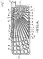
- Fig. 1 shows an enlarged view of one embodiment of a current collector 10 according to the present invention while Fig. 2 shows another embodiment of the present current collector 12 having a double wing configuration.
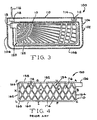
- Fig. 3 is of an exemplary electrochemical cell 100 of a multi-plate configuration comprising one of the present current collectors. Whether the current collector of the cell 100 is of the single wing configuration 10 or of the double wing type 12 is not necessarily important.
- the current collector 10 generally comprises wire or bar-shaped conductor strands in the shape of a frame 14 surrounding a grid 16 and supporting a tab 18.
- the conductors and tab are of a conductive material such as nickel, aluminum, copper, stainless steel, tant:alum, cobalt and titanium, and alloys thereof.
- the frame 14 has spaced apart upper and lower strands 20 and 22 extending to and meeting with left and right strands 24 and 26.
- Upper frame strand 20 meets left frame strand 24 at curved corner 28
- left frame strand 24 meets lower frame strand 22 at curved corner 30
- lower frame strand 22 meets right frame strand 26 at curved corner 32.
- Tab 18 is a generally solid planar member and extends outwardly from the junction of the upper frame strand 20 and the right frame strand 26.
- tab 18 includes upper and lower sides 34 and 36 extending to and meeting with an intermediate edge 38.
- the tab sides 34 and 36 are parallel to each other and are generally parallel to the upper and lower frame strands 20, 22.
- the upper tab side 34 is spaced somewhat below the upper frame strand 20 to provide a curved junction 40 where the upper strand 20 transitions into the upper tab side 34.
- the lower tab side 36 meets the right frame strand 26 at a perpendicular angle.
- the grid 16 is interior of and supported by the frame 14 and comprises a fan-shaped configuration of radial strands as conductors in the form of wires or elongate bars.
- the radial conductor strands are of two general types. Conductors 42, 44 and 46 begin at the tab 18 and radiate outwardly to terminate at either the left frame strand 24 (conductor 42) or the lower frame strand 22 (conductors 44 and 46). The other type of radial conductor begins at a position spaced from the tab 18 and radiates outwardly to terminate at either the left frame strand 24 or the lower frame strand 22. Regardless, both types of radial conductors have their terminus aimed at an imaginary focal point 48, indicated by the area outlined by the dashed lines, and residing on the tab 18.
- the grid structure further comprises a first and a second group of curved or concentric strands as conductors in the form of wires or elongated bars.
- the first group includes conductors 50, 52, 54, 56 and 58, which are at progressively greater distances from the focal point 48 and concentric therewith.
- Each of the first group of concentric conductors extends from the upper frame strand 20 to the right frame strand 26 and intersects with each of the radial conductors 42, 44 and 46 emanating from the focal point 48 of tab 18. Other of the radial conductors do not begin at the tab 18, but radiate outwardly from various ones of the first group of concentric conductors.
- radial conductors 60 and 62 both begin at concentric conductor 58 while radial conductor 64, intermediate conductors 60 and 62, begins at concentric conductor 50.
- Conductors 60, 62 and 64 terminate at the left frame strand 24.
- Radial conductor 66 begins at concentric conductor 54 and terminates in the vicinity of the curved corner 30 between the left frame strand 24 and the bottom frame strand 22.
- radial conductor 68, 70, 72, 74, 76, 78, 80, 82 and 84 begin at various ones of the first group of concentric conductors, but terminate at the lower frame strand 22.
- radial conductor 68 begins at concentric conductor 58.
- conductor 70 which is adjacent to focal point radial conductor 44, begins at concentric conductor 58.
- Radial conductors 72 and 74 begin at concentric conductors 54 and 58, respectively.
- Radial conductor 76 begins at concentric conductor 50
- radial conductor 78 begins at concentric conductor 54.
- conductors 80, 82 and 84 begin at concentric conductor 54 and terminate at the lower frame strand 22.
- Focal point radial conductor 46 is directly adjacent to radial conductors 78 and 80.
- the grid 16 is completed by the second group of curved strands comprising conductors 86, 88 and 90. As is the case with the first group of concentric conductors, these, too, are concentric with the focal point 48. However, they are spaced a substantial distance from the first group of concentric conductors 50, 52, 54, 56 and 58. The first group of concentric conductors 86, 88 and 90 extend from the upper frame strand 20 to the lower frame strand 22.
- the substantial distance from the first group of concentric conductors to the second group is defined as a factor of "x".
- the distance x is defined as being from the focal point 48 to the outer most radial conductor 58 of the first group.
- the distance from radial conductor 58 to the first one of the second group of radial conductors 86 is n(x) with n ranging from about 1 to about 10, and fractions thereof.
- the substantial distance between the two groups of radial conductors is measured along upper frame stand 20.
- the current collector need not necessarily have the generally rectangular frame shape shown. Instead, the frame can be squared, circular, or some other irregular shape dictated by the design requirements of a specific cell construction.
- the specific shape of the current collector, according to the present invention it has a series of radial conductors fanning out from a focal point and supported by spaced apart first and second groups of concentric conductors with the distance between the two groups of concentric conductors being at least "x", as measured is some direction from the focal point.
- a single concentric conductor is sufficient to constitute a group for the purpose of this invention.
- a concentric conductor need not necessarily connect to the spaced apart portions of the frame. It is within the scope of the present invention that any one of the first group of concentric conductors 50, 52, 54, 56 and 58 and of the second group of concentric conductors 86, 88 and 90 can terminate at one of the radiating conductors 42, 44, 46, 60, 62, 64, 66, 68, 70, 72, 74, 76, 78, 80, 82 and 84 and, in that respect, not terminate at the frame.
- the opposed ends of concentric conductor 58 terminate at radial conductors 42 and 84 instead of upper frame strand 20 and right frame strand 26, respectively.
- the opposed ends of centric conductor 84 terminate at radial conductors 42 and 68 instead of upper frame strand 20 and lower frame strand 22, respectively.
- the double wing current collector 12 of Fig. 2 is essentially comprised of two current collector portions 14, each similar to current collector 10 of Fig. 1 as mirror images of each other.
- the mirror image current collectors 14 are positioned side-by-side connected together at a tab 18.
- Fig. 3 shows the exemplary electrochemical cell 100 useful with either one of the current collectors 10, 12.
- the cell includes a casing 102 having spaced apart front and back side walls (not shown) joined by side walls 104 and 106 and a planar bottom wall 108. The junctions between the various side walls and bottom wall are curved.
- the open top of the casing 102 is closed by a lid 110.
- Lid 110 has an opening 112 that serves as a port for filling an electrolyte (not shown) into the casing after the cell internal components have been assembled therein and lid 110 has been sealed to the side walls.
- a sealing plug such as a ball 114, is hermetically sealed in the electrolyte fill opening 112 to close the cell in a gas tight manner.
- the casing 102, lid 110 and sealing ball 114 are preferably of a conductive material. Suitable materials include nickel, aluminum, stainless steel, mild steel, nickel plated mild steel and titanium. Preferably, the casing, lid and sealing ball are of the same material.
- a terminal lead 116 for one of the anode electrode and the cathode electrode is electrically insulated from the lid 110 and the casing 102 by a glass-to-metal seal 118.
- the lead 116 serves as the cathode terminal and the lid 110 and casing 102 serve as the negative or anode terminal, as is well known to those skilled in the art.
- a case-positive cell configuration has the positive electrode or cathode contacted to the casing 102 with the anode supported on the current collector 10 connected to the lead 116.
- the exemplary cell 100 shown in Fig. 3 includes a central electrode 120 comprising the current collector 10 of the present invention supporting at least one of the opposite polarity active materials.
- the active materials are not shown supported on the current collector 10.
- current collector 10 supports opposed layers of cathode active material contacting the opposite major sides thereof locked together through its many open areas.
- the tab 18 is then connected to the terminal lead 116 such as by welding.
- anode active material is locked together supported on the opposite major sides of the current collector.
- the central electrode 120 of cell 100 is sealed in a separator envelope 122 to prevent direct contact with the opposite polarity electrode.
- the opposite polarity electrode is the anode comprised of anode active material contacted to the inner major sides of the current collector 12 shown in Fig. 2.
- the wing portions 12A and 12B of collector 12, joined by the intermediate tab 18A, are folded downwardly toward each other with respect to tab 18A and into electrical association with the opposed major sides of the intermediate cathode.
- the opposed cathode plates are carried by the wing portions 12A, 12B and folded down toward each other and with respect to tab 18A into electrical association with the opposed major sides of the central anode.
- Current collector 150 is comprised wire or bar-shaped conductor strands in the shape of a frame 152 surrounding a grid 154 and supporting a tab 156.
- the frame 152 has spaced apart upper and lower strands 158 and 160 extending to and meeting with left and right strands 162 and 164.
- Upper frame strand 158 meets left frame strand 162 at curved corner 166
- left frame strand 162 meets lower frame strand 160 at curved corner 168
- lower frame strand 160 meets right frame strand 164 at curved corner 170.
- the grid 154 is comprised of a plurality of intersecting wire or bar-shaped conductor strands 172 and 174.
- Conductors 172 are parallel to each other as are conductors 174.
- Conductors 172 extend from the upper frame strand 158 to either the lower frame strand 160 or the left frame strand 162 while conductors 174 extend from the upper frame strand 158 to either the lower frame strand 160 or the right frame strand 164.
- This provides the grid 154 having a plurality of diamond shaped openings 176, and portions thereof, formed between the intersecting conductors 172, 174.
- a power source 178 having positive and negative leads 180 and 182 (Fig. 5) was set at a current of 0.182 Amperes, which is equal to the current for one electrode plate in a typical battery powering an implantable medical device.
- the positive lead 180 was placed on node C which corresponds to the focal point 48 of tab 18 of collector 10 and on the tab 156 of current collector 150.
- the negative lead 182 was then placed on the other nodes A, B and D to L.
- the voltage drop between these node points was measured using a multimeter 184 having positive and negative leads 186 and 188 by placing the positive multimeter lead on node C and the negative multimeter lead 188 on the node on which the negative power supply lead 182 was contacted.
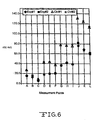
- the Rdc measurements for two current collectors of each of the present invention and the prior art are set forth below in Table 1 and in the graph of Fig. 6. This data clearly illustrate that the novel current collectors 10, 12 of the present invention have significantly lower Rdc than the prior art current collector 150 described in Fig. 4.
Landscapes
- Chemical & Material Sciences (AREA)
- Chemical Kinetics & Catalysis (AREA)
- Electrochemistry (AREA)
- General Chemical & Material Sciences (AREA)
- Engineering & Computer Science (AREA)
- Manufacturing & Machinery (AREA)
- Cell Electrode Carriers And Collectors (AREA)
- Connection Of Batteries Or Terminals (AREA)
- Electric Double-Layer Capacitors Or The Like (AREA)
- Secondary Cells (AREA)
Claims (11)
- Stromkollektor, der umfasst:a) einen Rahmen, der wenigstens einen Rahmenleiter umfasst, der einen geschlossenen Umfang schafft;b) mehrere erste strahlenförmig verlaufende Leiter, die von einem Fokuspunkt auf dem Rahmen strahlenförmig verlaufen und am Rahmenumfang in einem Abstand vom Fokuspunkt enden;c) eine erste Gruppe mehrerer konzentrischer Leiter, die zu dem Fokuspunkt konzentrisch sind und die mehreren strahlenförmig verlaufenden Leiter schneiden;d) eine zweite Gruppe mehrerer konzentrischer Leiter, die zu dem Fokuspunkt konzentrisch sind und die mehreren strahlenförmig verlaufenden Leiter schneiden; unde) wobei der Abstand zwischen dem Fokuspunkt und dem äußeren konzentrischen Leiter der ersten Gruppe konzentrischer Leiter durch "x" gegeben ist und der Abstand vom äußeren konzentrischen Leiter der ersten Gruppe zu dem inneren konzentrischen Leiter der zweiten Gruppe im Bereich von 1x bis 10x liegt und wobei zwischen dem äußeren konzentrischen Leiter der ersten Gruppe und dem inneren konzentrischen Leiter der zweiten Gruppe keine konzentrischen Leiter vorhanden sind.
- Stromkollektor nach Anspruch 1, bei dem:a) sich die erste Gruppe konzentrischer Leiter von einem ersten und von einem hierzu beabstandeten zweiten Rahmenabschnitt des Rahmenumfangs ausbreitet und die erste Gruppe konzentrischer Leiter auf einen ersten und auf einen hierzu beabstandeten zweiten Rahmenabschnitt des Rahmenumfangs trifft undb) sich die zweite Gruppe konzentrischer Leiter von einem dritten und von einem hierzu beabstandeten vierten Rahmenabschnitt des Rahmenumfangs ausbreitet und die zweite Gruppe konzentrischer Leiter auf einen dritten und auf einen hierzu beabstandeten vierten Rahmenabschnitt des Rahmenumfangs trifft.
- Stromkollektor nach einem vorhergehenden Anspruch, bei dem sich die konzentrischen Leiter der ersten Gruppe von einem ersten und von einem hierzu beabstandeten zweiten Rahmenabschnitt des Rahmens ausbreiten und bei dem die konzentrischen Leiter der ersten Gruppe auf einen ersten und auf einen hierzu beabstandeten zweiten Rahmenabschnitt des Rahmens treffen.
- Stromkollektor nach einem vorhergehenden Anspruch, bei dem sich die konzentrischen Leiter der zweiten Gruppe von einem dritten und von einem hierzu beabstandeten vierten Rahmenabschnitt des Rahmens ausbreiten und bei dem die konzentrischen Leiter der zweiten Gruppe auf einen dritten und einen hierzu beabstandeten vierten Rahmenabschnitt des Rahmens treffen.
- Stromkollektor nach einem vorhergehenden Anspruch, bei dem mehrere zweite strahlenförmig verlaufende Leiter vorhanden sind, die von der ersten Gruppe konzentrischer Leiter zu der zweiten Gruppe konzentrischer Leiter strahlenförmig verlaufen und im Fokuspunkt zusammenlaufen, und bei dem die zweiten strahlenförmig verlaufenden Leiter nicht vom Fokuspunkt ausgehend strahlenförmig verlaufen.
- Stromkollektor nach einem vorhergehenden Anspruch, bei dem der Fokuspunkt auf einem Kollektorstreifen liegt, der sich vom Rahmen nach außen erstreckt.
- Stromkollektor nach einem vorhergehenden Anspruch, bei dem der Rahmen eine im Allgemeinen rechteckige Form hat, die einen ersten und einen hierzu beabstandeten zweiten Rahmenleiter umfasst, die sich zu einem dritten und zu einem vierten Rahmenleiter ausbreiten und auf den dritten und vierten Rahmenleiter treffen, und bei dem der erste und der zweite Rahmenleiter länger als der dritte und der vierte Rahmenleiter sind.
- Stromkollektor nach einem vorhergehenden Anspruch, bei dem der Fokuspunkt auf einem Kollektorstreifen vorhanden ist, der sich von der Verbindung des ersten oder zweiten Rahmenleiters ausbreitet und auf den dritten oder vierten Rahmenleiter trifft.
- Stromkollektor nach einem vorhergehenden Anspruch aus einem leitenden Werkstoff, der aus der Gruppe gewählt ist, die aus Nickel, Kupfer, Titan, Cobalt, Tantat, Aluminium, rostfreiem Stahl und Legierungen hiervon besteht.
- Verfahren für die Schaffung einer elektrochemischen Zelle, das die folgenden Schritte umfasst:a) Vorsehen eines ersten Stromkollektors, der umfasst: einen Rahmen, der wenigstens einen Rahmenleiter umfasst, der einen geschlossenen Umfang schafft; mehrere erste strahlenförmig verlaufende Leiter, die ausgehend von einem Fokuspunkt auf dem Rahmen strahlenförmig verlaufen und am Rahmenumfang, der vom Fokuspunkt beabstandet ist, enden; eine erste Gruppe mehrerer konzentrischer Leiter, die zu dem Fokuspunkt konzentrisch sind und die mehreren strahlenförmig verlaufenden Leiter schneiden; eine zweite Gruppe mehrerer konzentrischer Leiter, die zu dem Fokuspunkt konzentrisch sind und die mehreren strahlenförmig verlaufenden Leiter schneiden; wobei der Abstand zwischen dem Fokuspunkt und dem äußeren konzentrischen Leiter der ersten Gruppe konzentrischer Leiter durch "x" gegeben ist und der Abstand vom äußeren konzentrischen Leiter der ersten Gruppe zum inneren konzentrischen Leiter der zweiten Gruppe im Bereich von 1x bis 10x liegt und wobei zwischen dem äußeren konzentrischen Leiter der ersten Gruppe und dem inneren konzentrischen Leiter der zweiten Gruppe keine konzentrischen Leiter vorhanden sind;b) Herstellen eines Kontakts zwischen einem ersten aktiven Elektrodenmaterial mit einer ersten und/oder einer zweiten Hauptseite des ersten Stromkollektors, der mit einem ersten Anschluss verbunden ist, um eine erste Elektrode zu schaffen;c) elektrisches Zuordnen der ersten Elektrode zu einer zweiten Gegenelektrode, die mit einem zweiten Anschluss verbunden und in einem Gehäuse untergebracht ist; undd) Aktivieren der ersten und der zweiten Elektrode mit einem Elektrolyt.
- Verfahren nach Anspruch 10, das das Vorsehen der zweiten Elektrode umfasst, die ein zweites aktives Elektrodenmaterial enthält, das mit einem zweiten Stromkollektor in Kontakt ist, der zwei der ersten Stromkollektoren in einer nebeneinanderliegenden Doppelflügelkonfiguration mit einem Zwischenstreifen umfasst, wobei das zweite aktive Elektrodenmaterial wenigstens mit einer Hauptseite jedes der Flügel des zweiten Stromkollektors in Kontakt ist, und bei dem die erste Elektrode zwischen den Flügeln der zweiten Elektrode vorgesehen wird und die Flügel zu der ersten Elektrode gefaltet werden, um die erste Elektrode der zweiten Elektrode, die voneinander durch eine Trennvorrichtung getrennt sind, elektrisch zuzuordnen.
Applications Claiming Priority (2)
| Application Number | Priority Date | Filing Date | Title |
|---|---|---|---|
| US269131 | 1988-11-09 | ||
| US26913101P | 2001-02-15 | 2001-02-15 |
Publications (2)
| Publication Number | Publication Date |
|---|---|
| EP1233465A1 EP1233465A1 (de) | 2002-08-21 |
| EP1233465B1 true EP1233465B1 (de) | 2005-01-26 |
Family
ID=23025927
Family Applications (1)
| Application Number | Title | Priority Date | Filing Date |
|---|---|---|---|
| EP02251050A Expired - Lifetime EP1233465B1 (de) | 2001-02-15 | 2002-02-15 | Stromkollektorplatte mit asymmetrischem, von einem gemeinsamen Brennpunkt ausgehenden Rippenmuster |
Country Status (6)
| Country | Link |
|---|---|
| US (1) | US6893777B2 (de) |
| EP (1) | EP1233465B1 (de) |
| JP (1) | JP2002289199A (de) |
| AT (1) | ATE288137T1 (de) |
| CA (1) | CA2371542A1 (de) |
| DE (1) | DE60202701D1 (de) |
Families Citing this family (29)
| Publication number | Priority date | Publication date | Assignee | Title |
|---|---|---|---|---|
| EP1959461A1 (de) * | 2005-11-14 | 2008-08-20 | Matsushita Electric Industrial Co., Ltd. | Elektrischer doppelschichtkondensator |
| JP4225334B2 (ja) * | 2006-08-25 | 2009-02-18 | トヨタ自動車株式会社 | 蓄電装置用電極および蓄電装置 |
| US8236442B2 (en) * | 2008-01-31 | 2012-08-07 | Medtronic, Inc. | Asymmetric aperture pattern in a current collector for an electrochemical cell |
| US20090197170A1 (en) * | 2008-01-31 | 2009-08-06 | Viavattine Joseph J | Maximization of active material to collector interfacial area |
| KR20100137530A (ko) * | 2008-03-25 | 2010-12-30 | 에이일이삼 시스템즈 인코포레이티드 | 고에너지 고출력 전극 및 배터리 |
| US8741487B1 (en) | 2008-08-28 | 2014-06-03 | Greatbatch Ltd. | Electrode current collector with stress-relieving mesh structure |
| US8023250B2 (en) * | 2008-09-12 | 2011-09-20 | Avx Corporation | Substrate for use in wet capacitors |
| US8279585B2 (en) * | 2008-12-09 | 2012-10-02 | Avx Corporation | Cathode for use in a wet capacitor |
| US8405956B2 (en) | 2009-06-01 | 2013-03-26 | Avx Corporation | High voltage electrolytic capacitors |
| US20120288747A1 (en) * | 2010-01-29 | 2012-11-15 | Jsr Corporation | Electrochemical device |
| US8605411B2 (en) | 2010-09-16 | 2013-12-10 | Avx Corporation | Abrasive blasted conductive polymer cathode for use in a wet electrolytic capacitor |
| US8514547B2 (en) | 2010-11-01 | 2013-08-20 | Avx Corporation | Volumetrically efficient wet electrolytic capacitor |
| US8259435B2 (en) | 2010-11-01 | 2012-09-04 | Avx Corporation | Hermetically sealed wet electrolytic capacitor |
| US9105401B2 (en) | 2011-12-02 | 2015-08-11 | Avx Corporation | Wet electrolytic capacitor containing a gelled working electrolyte |
| US9129747B2 (en) | 2012-03-16 | 2015-09-08 | Avx Corporation | Abrasive blasted cathode of a wet electrolytic capacitor |
| KR20130132231A (ko) * | 2012-05-25 | 2013-12-04 | 주식회사 엘지화학 | 단차를 갖는 전극 조립체 및 이를 포함하는 전지셀, 전지팩 및 디바이스 |
| US9963362B2 (en) * | 2013-03-15 | 2018-05-08 | Southern Methodist University | Method for electrochemical bromide and/or chloride removal |
| US9455448B1 (en) | 2013-08-23 | 2016-09-27 | Greatbatch Ltd. | Multi-thickness current collector |
| KR101709546B1 (ko) * | 2014-05-08 | 2017-03-08 | 주식회사 엘지화학 | 유연성 집전체를 포함하는 전지셀 |
| DE102016220975A1 (de) | 2016-10-25 | 2018-04-26 | Robert Bosch Gmbh | Stromkollektor für eine Energiespeicherzelle zum Speichern elektrischer Energie |
| US12451493B2 (en) | 2017-01-27 | 2025-10-21 | Cps Technology Holdings Llc | Battery grid |
| EP3635805B1 (de) | 2017-06-09 | 2023-09-06 | CPS Technology Holdings LLC | Bleibatterie |
| US11936032B2 (en) | 2017-06-09 | 2024-03-19 | Cps Technology Holdings Llc | Absorbent glass mat battery |
| CN107591570B (zh) * | 2017-09-05 | 2019-08-09 | 李开贵 | 一种纳米硅胶体蓄电池 |
| US11075388B1 (en) | 2017-11-10 | 2021-07-27 | Greatbatch Ltd. | Foil-type current collector having an unperforated strip at the connector tab |
| WO2019151063A1 (ja) * | 2018-01-30 | 2019-08-08 | シャープ株式会社 | 金属空気電池用負極 |
| US20230027323A1 (en) * | 2021-07-20 | 2023-01-26 | GM Global Technology Operations LLC | Electrode coating using a porous current collector |
| US12512274B2 (en) | 2022-08-26 | 2025-12-30 | KYOCERA AVX Components Corporation | Wet electrolytic capacitor containing a gelled working electrolyte |
| US20250273694A1 (en) * | 2024-02-22 | 2025-08-28 | Form Energy, Inc. | Current collecting in metal-air batteries |
Family Cites Families (24)
| Publication number | Priority date | Publication date | Assignee | Title |
|---|---|---|---|---|
| US1044831A (en) * | 1912-07-08 | 1912-11-19 | Peerless Motor Car Company | Storage-battery grid. |
| US1528963A (en) | 1920-08-19 | 1925-03-10 | Edward S Adams | Grid for storage-battery plates |
| US1440354A (en) | 1922-04-08 | 1922-12-26 | John N Hanna | Battery plate |
| US2503970A (en) | 1945-05-12 | 1950-04-11 | Nat Battery Co | Storage battery grid |
| FR1010039A (fr) | 1948-07-23 | 1952-06-06 | Perfectionnements à la construction et au fonctionnement des accumulateurs électriques | |
| GB1104093A (en) | 1962-11-12 | 1968-02-21 | Pritchett & Gold & E P S Co | Improvements relating to electrodes for storage batteries |
| US3434883A (en) | 1966-05-23 | 1969-03-25 | Bell Telephone Labor Inc | Cylindrical lead acid cell |
| US3453145A (en) * | 1967-11-03 | 1969-07-01 | Esb Inc | Battery plate having laminar grid |
| US3989539A (en) | 1975-12-01 | 1976-11-02 | Varta Batteries Ltd. | Battery grid |
| ZA771344B (en) | 1976-05-17 | 1978-04-26 | Globe Union Inc | Composite article and method of manufacturing |
| US4091192A (en) * | 1977-01-26 | 1978-05-23 | Scholle Corporation | Paired battery grids with severable brace, plastic lugs, and lead lug |
| US4221852A (en) | 1979-05-21 | 1980-09-09 | Esb United States, Inc. | Radial grids for lead acid batteries |
| US4250235A (en) | 1979-08-16 | 1981-02-10 | Hughes Aircraft Company | Battery electrode structure |
| US4320183A (en) | 1981-02-09 | 1982-03-16 | Exide Corporation | Grid for batteries |
| AU567698B2 (en) | 1982-10-29 | 1987-12-03 | Chloride Group Public Limited Company | Grids for storage battery |
| US4477546A (en) | 1983-02-03 | 1984-10-16 | Eagle-Picher Industries, Inc. | Lattice for a battery electrode substrate |
| JPS60150556A (ja) | 1984-01-13 | 1985-08-08 | Japan Storage Battery Co Ltd | 鉛蓄電池用格子 |
| US5169659A (en) | 1989-08-18 | 1992-12-08 | Exide Corporation | Hot climate battery |
| AU661859B2 (en) * | 1991-09-10 | 1995-08-10 | Wilson Greatbatch Ltd. | Twin plate cathode assembly for multiplate, electrochemical cells |
| CN1034039C (zh) | 1992-10-19 | 1997-02-12 | 南开大学森力高技术实业公司 | 大容量电动车用镍-氢化物蓄电池 |
| US5498496A (en) | 1993-12-14 | 1996-03-12 | Yuasa Corporation | Lead acid battery |
| US5582936A (en) | 1994-11-16 | 1996-12-10 | Globe-Union, Inc. | Lead-acid batteries with optimum current collection at grid lugs |
| US5989749A (en) | 1997-11-26 | 1999-11-23 | Johnson Controls Technology Company | Stamped battery grid |
| US6566010B1 (en) * | 2000-11-16 | 2003-05-20 | Concorde Battery Corporation | High energy, lightweight, lead-acid storage battery |
-
2002
- 2002-02-12 US US10/074,369 patent/US6893777B2/en not_active Expired - Fee Related
- 2002-02-14 CA CA002371542A patent/CA2371542A1/en not_active Abandoned
- 2002-02-15 AT AT02251050T patent/ATE288137T1/de not_active IP Right Cessation
- 2002-02-15 JP JP2002082127A patent/JP2002289199A/ja active Pending
- 2002-02-15 DE DE60202701T patent/DE60202701D1/de not_active Expired - Fee Related
- 2002-02-15 EP EP02251050A patent/EP1233465B1/de not_active Expired - Lifetime
Also Published As
| Publication number | Publication date |
|---|---|
| US6893777B2 (en) | 2005-05-17 |
| EP1233465A1 (de) | 2002-08-21 |
| JP2002289199A (ja) | 2002-10-04 |
| CA2371542A1 (en) | 2002-08-15 |
| ATE288137T1 (de) | 2005-02-15 |
| DE60202701D1 (de) | 2005-03-03 |
| US20020146625A1 (en) | 2002-10-10 |
Similar Documents
| Publication | Publication Date | Title |
|---|---|---|
| EP1233465B1 (de) | Stromkollektorplatte mit asymmetrischem, von einem gemeinsamen Brennpunkt ausgehenden Rippenmuster | |
| US7000297B2 (en) | Electrochemical cell current collector having openings of progressively larger sizes converging at a tab | |
| US7285355B2 (en) | Battery | |
| US7736793B2 (en) | Secondary battery with collector plate and electrode package thereof | |
| US5667909A (en) | Electrodes configured for high energy density galvanic cells | |
| KR100599792B1 (ko) | 이차 전지와 이에 사용되는 전극 조립체 및 집전판 | |
| JP3429428B2 (ja) | エネルギー貯蔵装置用集電体 | |
| US20010008725A1 (en) | Current collector for lithium electrode | |
| US6037077A (en) | Electrode assembly for high energy devices | |
| US8043746B2 (en) | Electrical connection for a storage cell | |
| US6703162B2 (en) | Battery and process for examining battery | |
| JPS62501248A (ja) | 巻回された電極構造をもつ電気化学セル | |
| US5716735A (en) | Twin plate cathode assembly for multiplate, electrochemical cells | |
| US6423442B1 (en) | Cell stack design with bi-directionally wound slotted electrodes and method for making | |
| US7385802B1 (en) | Electrolytic capacitor | |
| JPH08255609A (ja) | 電気化学電池および電池ケース内での電極の運動を防止する方法 | |
| KR100599713B1 (ko) | 이차 전지와 이에 사용되는 전극 조립체 | |
| US7964306B2 (en) | Lithium rechargeable battery having electrode pin | |
| CN2849999Y (zh) | 锂离子电池 | |
| US20020150817A1 (en) | Low profile battery termination | |
| CN100369296C (zh) | 蓄电池 | |
| US20210399393A1 (en) | Electrical connection of electrode tabs of an electromechanical cell | |
| KR100788559B1 (ko) | 이차전지 | |
| CN224204302U (zh) | 一种电芯壳体组件及电芯 | |
| US20210167349A1 (en) | Batteries and Methods of Using and Making the Same |
Legal Events
| Date | Code | Title | Description |
|---|---|---|---|
| PUAI | Public reference made under article 153(3) epc to a published international application that has entered the european phase |
Free format text: ORIGINAL CODE: 0009012 |
|
| AK | Designated contracting states |
Kind code of ref document: A1 Designated state(s): AT BE CH CY DE DK ES FI FR GB GR IE IT LI LU MC NL PT SE TR |
|
| AX | Request for extension of the european patent |
Free format text: AL;LT;LV;MK;RO;SI |
|
| 17P | Request for examination filed |
Effective date: 20020920 |
|
| 17Q | First examination report despatched |
Effective date: 20021120 |
|
| AKX | Designation fees paid |
Designated state(s): AT BE CH CY DE DK ES FI FR GB GR IE IT LI LU MC NL PT SE TR |
|
| GRAP | Despatch of communication of intention to grant a patent |
Free format text: ORIGINAL CODE: EPIDOSNIGR1 |
|
| GRAS | Grant fee paid |
Free format text: ORIGINAL CODE: EPIDOSNIGR3 |
|
| GRAA | (expected) grant |
Free format text: ORIGINAL CODE: 0009210 |
|
| AK | Designated contracting states |
Kind code of ref document: B1 Designated state(s): AT BE CH CY DE DK ES FI FR GB GR IE IT LI LU MC NL PT SE TR |
|
| PG25 | Lapsed in a contracting state [announced via postgrant information from national office to epo] |
Ref country code: LI Free format text: LAPSE BECAUSE OF FAILURE TO SUBMIT A TRANSLATION OF THE DESCRIPTION OR TO PAY THE FEE WITHIN THE PRESCRIBED TIME-LIMIT Effective date: 20050126 Ref country code: FR Free format text: LAPSE BECAUSE OF NON-PAYMENT OF DUE FEES Effective date: 20050126 Ref country code: BE Free format text: LAPSE BECAUSE OF FAILURE TO SUBMIT A TRANSLATION OF THE DESCRIPTION OR TO PAY THE FEE WITHIN THE PRESCRIBED TIME-LIMIT Effective date: 20050126 Ref country code: IT Free format text: LAPSE BECAUSE OF FAILURE TO SUBMIT A TRANSLATION OF THE DESCRIPTION OR TO PAY THE FEE WITHIN THE PRESCRIBED TIME-LIMIT;WARNING: LAPSES OF ITALIAN PATENTS WITH EFFECTIVE DATE BEFORE 2007 MAY HAVE OCCURRED AT ANY TIME BEFORE 2007. THE CORRECT EFFECTIVE DATE MAY BE DIFFERENT FROM THE ONE RECORDED. Effective date: 20050126 Ref country code: AT Free format text: LAPSE BECAUSE OF FAILURE TO SUBMIT A TRANSLATION OF THE DESCRIPTION OR TO PAY THE FEE WITHIN THE PRESCRIBED TIME-LIMIT Effective date: 20050126 Ref country code: NL Free format text: LAPSE BECAUSE OF FAILURE TO SUBMIT A TRANSLATION OF THE DESCRIPTION OR TO PAY THE FEE WITHIN THE PRESCRIBED TIME-LIMIT Effective date: 20050126 Ref country code: FI Free format text: LAPSE BECAUSE OF FAILURE TO SUBMIT A TRANSLATION OF THE DESCRIPTION OR TO PAY THE FEE WITHIN THE PRESCRIBED TIME-LIMIT Effective date: 20050126 Ref country code: TR Free format text: LAPSE BECAUSE OF FAILURE TO SUBMIT A TRANSLATION OF THE DESCRIPTION OR TO PAY THE FEE WITHIN THE PRESCRIBED TIME-LIMIT Effective date: 20050126 Ref country code: CH Free format text: LAPSE BECAUSE OF FAILURE TO SUBMIT A TRANSLATION OF THE DESCRIPTION OR TO PAY THE FEE WITHIN THE PRESCRIBED TIME-LIMIT Effective date: 20050126 |
|
| REG | Reference to a national code |
Ref country code: GB Ref legal event code: FG4D |
|
| REG | Reference to a national code |
Ref country code: CH Ref legal event code: EP |
|
| PG25 | Lapsed in a contracting state [announced via postgrant information from national office to epo] |
Ref country code: LU Free format text: LAPSE BECAUSE OF NON-PAYMENT OF DUE FEES Effective date: 20050215 Ref country code: CY Free format text: LAPSE BECAUSE OF FAILURE TO SUBMIT A TRANSLATION OF THE DESCRIPTION OR TO PAY THE FEE WITHIN THE PRESCRIBED TIME-LIMIT Effective date: 20050215 Ref country code: IE Free format text: LAPSE BECAUSE OF NON-PAYMENT OF DUE FEES Effective date: 20050215 |
|
| REG | Reference to a national code |
Ref country code: IE Ref legal event code: FG4D |
|
| PG25 | Lapsed in a contracting state [announced via postgrant information from national office to epo] |
Ref country code: MC Free format text: LAPSE BECAUSE OF NON-PAYMENT OF DUE FEES Effective date: 20050228 |
|
| REF | Corresponds to: |
Ref document number: 60202701 Country of ref document: DE Date of ref document: 20050303 Kind code of ref document: P |
|
| PG25 | Lapsed in a contracting state [announced via postgrant information from national office to epo] |
Ref country code: DK Free format text: LAPSE BECAUSE OF FAILURE TO SUBMIT A TRANSLATION OF THE DESCRIPTION OR TO PAY THE FEE WITHIN THE PRESCRIBED TIME-LIMIT Effective date: 20050426 Ref country code: GR Free format text: LAPSE BECAUSE OF FAILURE TO SUBMIT A TRANSLATION OF THE DESCRIPTION OR TO PAY THE FEE WITHIN THE PRESCRIBED TIME-LIMIT Effective date: 20050426 Ref country code: SE Free format text: LAPSE BECAUSE OF FAILURE TO SUBMIT A TRANSLATION OF THE DESCRIPTION OR TO PAY THE FEE WITHIN THE PRESCRIBED TIME-LIMIT Effective date: 20050426 |
|
| PG25 | Lapsed in a contracting state [announced via postgrant information from national office to epo] |
Ref country code: ES Free format text: LAPSE BECAUSE OF FAILURE TO SUBMIT A TRANSLATION OF THE DESCRIPTION OR TO PAY THE FEE WITHIN THE PRESCRIBED TIME-LIMIT Effective date: 20050507 |
|
| NLV1 | Nl: lapsed or annulled due to failure to fulfill the requirements of art. 29p and 29m of the patents act | ||
| REG | Reference to a national code |
Ref country code: CH Ref legal event code: PL |
|
| PG25 | Lapsed in a contracting state [announced via postgrant information from national office to epo] |
Ref country code: DE Free format text: LAPSE BECAUSE OF NON-PAYMENT OF DUE FEES Effective date: 20050901 |
|
| REG | Reference to a national code |
Ref country code: IE Ref legal event code: MM4A |
|
| PLBE | No opposition filed within time limit |
Free format text: ORIGINAL CODE: 0009261 |
|
| STAA | Information on the status of an ep patent application or granted ep patent |
Free format text: STATUS: NO OPPOSITION FILED WITHIN TIME LIMIT |
|
| 26N | No opposition filed |
Effective date: 20051027 |
|
| PG25 | Lapsed in a contracting state [announced via postgrant information from national office to epo] |
Ref country code: GB Free format text: LAPSE BECAUSE OF NON-PAYMENT OF DUE FEES Effective date: 20060215 |
|
| EN | Fr: translation not filed | ||
| GBPC | Gb: european patent ceased through non-payment of renewal fee |
Effective date: 20060215 |
|
| PG25 | Lapsed in a contracting state [announced via postgrant information from national office to epo] |
Ref country code: PT Free format text: LAPSE BECAUSE OF NON-PAYMENT OF DUE FEES Effective date: 20050626 |