EP1233209A1 - Displacement device with a toothed belt engaging a gear rack - Google Patents
Displacement device with a toothed belt engaging a gear rack Download PDFInfo
- Publication number
- EP1233209A1 EP1233209A1 EP01810071A EP01810071A EP1233209A1 EP 1233209 A1 EP1233209 A1 EP 1233209A1 EP 01810071 A EP01810071 A EP 01810071A EP 01810071 A EP01810071 A EP 01810071A EP 1233209 A1 EP1233209 A1 EP 1233209A1
- Authority
- EP
- European Patent Office
- Prior art keywords
- rack
- toothed
- toothed belt
- pressing
- sliding device
- Prior art date
- Legal status (The legal status is an assumption and is not a legal conclusion. Google has not performed a legal analysis and makes no representation as to the accuracy of the status listed.)
- Granted
Links
Images


Classifications
-
- F—MECHANICAL ENGINEERING; LIGHTING; HEATING; WEAPONS; BLASTING
- F16—ENGINEERING ELEMENTS AND UNITS; GENERAL MEASURES FOR PRODUCING AND MAINTAINING EFFECTIVE FUNCTIONING OF MACHINES OR INSTALLATIONS; THERMAL INSULATION IN GENERAL
- F16H—GEARING
- F16H19/00—Gearings comprising essentially only toothed gears or friction members and not capable of conveying indefinitely-continuing rotary motion
- F16H19/02—Gearings comprising essentially only toothed gears or friction members and not capable of conveying indefinitely-continuing rotary motion for interconverting rotary or oscillating motion and reciprocating motion
- F16H19/06—Gearings comprising essentially only toothed gears or friction members and not capable of conveying indefinitely-continuing rotary motion for interconverting rotary or oscillating motion and reciprocating motion comprising flexible members, e.g. an endless flexible member
-
- B—PERFORMING OPERATIONS; TRANSPORTING
- B23—MACHINE TOOLS; METAL-WORKING NOT OTHERWISE PROVIDED FOR
- B23Q—DETAILS, COMPONENTS, OR ACCESSORIES FOR MACHINE TOOLS, e.g. ARRANGEMENTS FOR COPYING OR CONTROLLING; MACHINE TOOLS IN GENERAL CHARACTERISED BY THE CONSTRUCTION OF PARTICULAR DETAILS OR COMPONENTS; COMBINATIONS OR ASSOCIATIONS OF METAL-WORKING MACHINES, NOT DIRECTED TO A PARTICULAR RESULT
- B23Q5/00—Driving or feeding mechanisms; Control arrangements therefor
- B23Q5/22—Feeding members carrying tools or work
- B23Q5/34—Feeding other members supporting tools or work, e.g. saddles, tool-slides, through mechanical transmission
- B23Q5/38—Feeding other members supporting tools or work, e.g. saddles, tool-slides, through mechanical transmission feeding continuously
- B23Q5/385—Feeding other members supporting tools or work, e.g. saddles, tool-slides, through mechanical transmission feeding continuously using a gear and rack mechanism or a friction wheel co-operating with a rail
-
- F—MECHANICAL ENGINEERING; LIGHTING; HEATING; WEAPONS; BLASTING
- F16—ENGINEERING ELEMENTS AND UNITS; GENERAL MEASURES FOR PRODUCING AND MAINTAINING EFFECTIVE FUNCTIONING OF MACHINES OR INSTALLATIONS; THERMAL INSULATION IN GENERAL
- F16H—GEARING
- F16H19/00—Gearings comprising essentially only toothed gears or friction members and not capable of conveying indefinitely-continuing rotary motion
- F16H19/02—Gearings comprising essentially only toothed gears or friction members and not capable of conveying indefinitely-continuing rotary motion for interconverting rotary or oscillating motion and reciprocating motion
- F16H19/06—Gearings comprising essentially only toothed gears or friction members and not capable of conveying indefinitely-continuing rotary motion for interconverting rotary or oscillating motion and reciprocating motion comprising flexible members, e.g. an endless flexible member
- F16H2019/0613—Gearings comprising essentially only toothed gears or friction members and not capable of conveying indefinitely-continuing rotary motion for interconverting rotary or oscillating motion and reciprocating motion comprising flexible members, e.g. an endless flexible member the flexible member being a toothed belt or chain engaging a rack
-
- Y—GENERAL TAGGING OF NEW TECHNOLOGICAL DEVELOPMENTS; GENERAL TAGGING OF CROSS-SECTIONAL TECHNOLOGIES SPANNING OVER SEVERAL SECTIONS OF THE IPC; TECHNICAL SUBJECTS COVERED BY FORMER USPC CROSS-REFERENCE ART COLLECTIONS [XRACs] AND DIGESTS
- Y10—TECHNICAL SUBJECTS COVERED BY FORMER USPC
- Y10T—TECHNICAL SUBJECTS COVERED BY FORMER US CLASSIFICATION
- Y10T74/00—Machine element or mechanism
- Y10T74/18—Mechanical movements
- Y10T74/18568—Reciprocating or oscillating to or from alternating rotary
- Y10T74/18832—Reciprocating or oscillating to or from alternating rotary including flexible drive connector [e.g., belt, chain, strand, etc.]
- Y10T74/1884—Reciprocating or oscillating to or from alternating rotary including flexible drive connector [e.g., belt, chain, strand, etc.] with sprocket wheel
Definitions
- the invention relates to a displacement device according to the Preamble of claim 1.
- shifting devices can be used in different fields are such as in laboratory equipment, e.g. B. pipetting devices for chemical analysis and etc. ..
- the invention is based on the object generic shifting device to specify which works silently and trouble-free and a jerk-free and precisely controllable movement of the carriage is guaranteed and is simply constructed. This task is accomplished by the Invention as characterized in claim 1 solved.
- the advantages of the displacement device according to the invention are particularly useful in laboratory equipment, where the above properties are particularly desirable. That the power transmission is also maintenance-free, is a more essential, especially in a laboratory device Advantage.
- the displacement unit according to the invention is therefore suitable excellent for moving lifting and lowering Arms carrying pipettes or robotic arms for handling of test tubes, microtiter plates and the like etc. ..
- the displacement device has (FIG. 1) a guide 1 along which several carriages 2 are movable.
- the guide 1 comprises a Guide rod 3 formed round cross-section Guide rail, with which each of the carriage 2 by means of a Carriage 4 engages.
- Parallel to the guide rod 3 runs a rack 5 with upward Toothing.
- Each of the carriages 2 has one on the carriage 4 connecting drive unit 6 and one to this subsequent motor 7 to drive the same.
- the Drive unit 6 is a housing with a base plate 8 and a parallel cover plate 9 spaced from the same and between them a gear wheel to the rack 5 vertical axis formed drive wheel 10 which on the attached to the rack 5 vertical axis of the motor 7 and is driven by the same.
- a deflection wheel 11 is arranged, which is the same as the drive wheel 10, in particular also designed as a gear and whose axis is also perpendicular to the rack 5.
- the Drive wheel 10 and the deflection wheel 11 are both in the housing rotatable, but axially fixed.
- toothed belt 12 made of elastic Material, e.g. B. a plastic such as polyurethane, the one has internal toothing, which with said wheels engages as well as an external toothing, which with the Toothing of the rack 5 (see FIG. 4) engages.
- elastic Material e.g. B. a plastic such as polyurethane
- the pressure block 13 which is made of a material with good Sliding properties, preferably a suitable plastic how ultra high molecular weight low pressure polyethylene is made has a pressure surface 14, with which it against the the rack 5 opposite lower run of the Timing belt 12 presses.
- the pressing surface 14 has one straight middle section with several, z. B. three or four teeth of the external toothing of the toothed belt 12 overlapped and smooth on both sides convex curved sections.
- One for side guidance of the toothed belt 12 somewhat sunk upper Counter surface 15 is formed exactly the same and stands with the upper strand facing away from the rack 5 Timing belt 12 in contact.
- the distance between the pressing surface 14 and the counter surface 15 slightly larger than the inner radius - d. H. the radius apart from the toothing - des Drive wheel 10 and the deflection wheel 11.
- the Center distance of the said wheels so dimensioned that the Timing belt 12 is stretched slightly elastically. So that’s practicing upper strand of the same over the counter surface 15 an elastic Force on the pressure block 13, so that Pressing surface 14 in turn against rack 5 directed elastic force on the middle section of the exerts lower run of the toothed belt 12, which the same the rack 5 presses.
- the drive unit 6, in particular the arrangement consisting of the drive wheel 10, the deflection wheel 11, the toothed belt 12 and the pressure block 13 is with respect to one in the middle between the axes of the said wheels lying vertical plane essentially symmetrical.
- the carriages 2 are each replaced by appropriate ones Control of the motors 7 driven independently and the carriage 2 moved along the guide 1.
- the lower Run of the toothed belt 12 is in each case from the Direction of movement independently if it is with the convex section of the pressing surface in each case 14 comes into contact and continues to slide over it, so on the rack 5 pressed that the engagement of his external gearing with the same against the middle of the Drive unit 6 steadily reinforced over a short distance remains the same and then steadily decreases again. friction between the teeth and corresponding sounds and Irregularities in the movement become extensive as a result avoided.
- the Drive unit (Fig. 5a-c) is the pressing part as Pressure wheel 13 'formed a pinion that between the upper and lower run of the toothed belt 12 rotatable is arranged and its interlocking with its inner Interlocking meshes above and below.
- the base plate 8 and Cover plate 9 stops limited.
- Diameter is slightly larger than that of the drive wheel 10 and the deflection wheel 11 and the toothed belt 12 in turn is slightly elastically stretched, it transmits (see a. Fig.
Abstract
Description
Die Erfindung betrifft eine Verschiebeeinrichtung gemäss dem
Oberbegriff des Anspruchs 1. Derartige Verschiebeeinrichtungen
können auf verschiedenen Gebieten eingesetzt
werden wie etwa bei Laborgeräten, z. B. Pipettiereinrichtungen
für chemische Analysen u. dgl..The invention relates to a displacement device according to the
Preamble of
Es sind gattungsgemässe Verschiebeeinrichtungen bekannt, bei denen das als Zahnrad ausgebildete Antriebsrad unmittelbar mit der Zahnstange eingreift. Vor allem bei grösserer Länge der Zahnstange können jedoch Schwankungen des Abstandes oder der Winkellage zwischen derselben und der Achse des Zahnrades auftreten, was zu Geräuschentwicklung und Klemmen führen kann und die Genauigkeit der Positionierung und Gleichmässigkeit der Bewegung des Wagens beeinträchigt.Generic shifting devices are known at which the drive wheel designed as a gear wheel directly engages with the rack. Especially with longer lengths However, the rack can fluctuate in distance or the angular position between the same and the axis of the Gear occur, resulting in noise and jamming can lead and the accuracy of positioning and Uniformity of the movement of the carriage is impaired.
Der Erfindung liegt die Aufgabe zu Grunde, eine
gattungsgemässe Verschiebeeinrichtung anzugeben, welche
geräuschlos und störungsfrei funktioniert und eine ruckfreie
und genau steuerbare Bewegung des Wagens gewährleistet und
dabei einfach aufgebaut ist. Diese Aufgabe wird durch die
Erfindung, wie sie im Anspruch 1 gekennzeichnet ist, gelöst.The invention is based on the object
generic shifting device to specify which
works silently and trouble-free and a jerk-free
and precisely controllable movement of the carriage is guaranteed and
is simply constructed. This task is accomplished by the
Invention as characterized in
Die Vorteile der erfindungsgemässen Verschiebeeinrichtung kommen vor allem in Laborgeräten zum Tragen, wo die obengenannten Eigenschaften besonders erwünscht sind. Dass die Kraftübertragung ausserdem wartungsfrei ist, ist ein weiterer insbesondere bei einem Laborgerät wesentlicher Vorteil. Daher eignet sich die erfindungsgemässe Verschiebeeinheit hervorragend zum Verschieben von heb- und senkbare Pipetten tragenden Armen oder von Robotarmen zur Handhabung von Proberöhren, Mikrotiterplatten u. ä..The advantages of the displacement device according to the invention are particularly useful in laboratory equipment, where the above properties are particularly desirable. That the power transmission is also maintenance-free, is a more essential, especially in a laboratory device Advantage. The displacement unit according to the invention is therefore suitable excellent for moving lifting and lowering Arms carrying pipettes or robotic arms for handling of test tubes, microtiter plates and the like etc. ..
Im folgenden wird die Erfindung anhand von Figuren, welche lediglich Ausführungsbeispiele darstellen, näher erläutert. Es zeigen
- Fig. 1
- perspektivisch eine erfindungsgemässe Verschiebeeinrichtung mit mehreren Wagen,
- Fig. 2
- perspektivisch einen Motor und einen Teil einer Antriebseinheit mit abgenommenen Gehäuseteilen eines Wagens der erfindungsgemässen Verschiebeeinrichtung nach Fig. 1,
- Fig. 3a
- einen vertikalen Längsschnitt durch die Antriebseinheit,
- Fig. 3b
- einen horizontalen Längsschnitt durch die Antriebseinheit entsprechend B-B in Fig. 3a und Draufsicht auf den Motor,
- Fig. 3c
- einen Querschnitt durch die Antriebseinheit entsprechend C-C in Fig. 3a,
- Fig. 3d
- einen Querschnitt durch die Antriebseinheit entsprechend D-D in Fig. 3a,
- Fig. 4
- einen Teil der erfindungsgemässen Verschiebeeinrichtung, mit vertikalem Längsschnitt durch die Antriebseinheit,
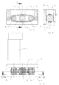
- Fig. 5a
- eine Draufsicht auf die Antriebseinheit und den Motor eines Wagens gemäss einer abgewandelten Ausführungsform der erfindungsgemässen Verschiebeeinrichtung nach Fig. 1,
- Fig. 5b
- einen vertikalen Längsschnitt durch die Antriebseinheit entsprechend B-B in Fig. 5a,
- Fig. 5c
- einen Querschnitt durch die Antriebseinheit entsprechend C-C in Fig. 5b und
- Fig. 6
- einen Teil der erfindungsgemässen Verschiebeeinrichtung gemäss der abgewandelten Ausführungsform, mit vertikalem Längsschnitt durch die Antriebseinheit.
- Fig. 1
- in perspective an inventive shifting device with several carriages,
- Fig. 2
- perspective a motor and part of a drive unit with removed housing parts of a carriage of the inventive shifting device according to FIG. 1,
- Fig. 3a
- a vertical longitudinal section through the drive unit,
- Fig. 3b
- 3 shows a horizontal longitudinal section through the drive unit corresponding to BB in FIG. 3a and a top view of the motor,
- Fig. 3c
- 3 shows a cross section through the drive unit corresponding to CC in FIG. 3a,
- Fig. 3d
- a cross section through the drive unit corresponding to DD in Fig. 3a,
- Fig. 4
- a part of the displacement device according to the invention, with a vertical longitudinal section through the drive unit,
- Fig. 5a
- 2 shows a plan view of the drive unit and the motor of a carriage according to a modified embodiment of the displacement device according to the invention according to FIG. 1,
- Fig. 5b
- a vertical longitudinal section through the drive unit corresponding to BB in Fig. 5a,
- Fig. 5c
- a cross section through the drive unit corresponding to CC in Fig. 5b and
- Fig. 6
- a part of the displacement device according to the invention according to the modified embodiment, with a vertical longitudinal section through the drive unit.
Die erfindungsgemässe Verschiebeeinrichtung weist (Fig. 1)
eine Führung 1 auf, längs welcher mehrere Wagen 2
verschiebbar sind. Die Führung 1 umfasst eine als
Führungsstange 3 runden Querschnitts ausgebildete
Führungsschiene, mit welcher jeder der Wagen 2 mittels eines
Schlittens 4 eingreift. Parallel zur Führungsstange 3
verläuft eine Zahnstange 5 mit nach oben weisender
Verzahnung. Jeder der Wagen 2 weist eine an den Schlitten 4
anschliessende Antriebseinheit 6 und einen an diese
anschliessenden Motor 7 zum Antrieb derselben auf. The displacement device according to the invention has (FIG. 1)
a
Wie aus Fig. 2, 3a-d ersichtlich, umfasst die
Antriebseinheit 6 ein Gehäuse mit einer Grundplatte 8 und
einer von derselben beabstandeten parallelen Deckplatte 9
und zwischen denselben ein als Zahnrad mit zur Zahnstange 5
senkrechter Achse ausgebildetes Antriebsrad 10, das an der
zur Zahnstange 5 senkrechten Achse des Motors 7 befestigt
ist und von demselben angetrieben wird. In Längsrichtung der
Zahnstange 5 gegenüber dem Antriebsrad 10 versetzt ist,
ebenfalls zwischen der Grundplatte 8 und der Deckplatte 9,
ein Umlenkrad 11 angeordnet, das gleich wie das Antriebsrad
10, insbesondere ebenfalls als Zahnrad ausgebildet und
dessen Achse ebenfalls senkrecht zur Zahnstange 5 ist. Das
Antriebsrad 10 und das Umlenkrad 11 sind beide im Gehäuse
drehbar, aber achsfest gelagert. Um das Antriebsrad 10 und
das Umlenkrad 11 läuft ein Zahnriemen 12 aus elastischem
Material, z. B. einem Kunststoff wie Polyurethan, der eine
innere Verzahnung aufweist, welche mit den besagten Rädern
eingreift sowie eine äussere Verzahnung, die mit der
Verzahnung der Zahnstange 5 (s. Fig. 4) eingreift.As can be seen from FIGS. 2, 3a-d, the
Zwischen dem Antriebsrad 10 und dem Umlenkrad 11 ist eine
Andrückvorrichtung angeordnet, die ein als unverdrehbarer
Andrückblock 13 ausgebildetes Antriebsteil umfasst, welches,
abgesehen von Anschlägen, die seine Verschieblichkeit
parallel zur Zahnstange 5 und parallel zu den Achsen der
Räder beschränkt, lediglich mit dem Zahnriemen 12 in Kontakt
ist. Der Andrückblock 13, der aus einem Material mit guten
Gleiteigenschaften, vorzugsweise einem geeigneten Kunststoff
wie ultrahochmolekularem Niederdruckpolyethylen besteht,
weist eine Andrückfläche 14 auf, mit welcher er gegen das
der Zahnstange 5 gegenüberliegende untere Trum des
Zahnriemens 12 drückt. Die Andrückfläche 14 weist einen
geraden mittleren Abschnitt auf, der mit mehreren, z. B.
drei oder vier Zähnen der Aussenverzahnung des Zahnriemens
12 überlappt und beidseitig glatt daran anschliessende
konvex gekrümmte Abschnitte. Eine zwecks seitlicher Führung
des Zahnriemens 12 etwas versenkt angeordnete obere
Gegenfläche 15 ist genau gleich ausgebildet und steht mit
dem von der Zahnstange 5 abgewandten oberen Trum des
Zahnriemens 12 in Kontakt.Between the
In der Mitte ist der Abstand zwischen der Andrückfläche 14
und der Gegenfläche 15 etwas grösser als der innere Radius -
d. h. der Radius abgesehen von der Verzahnung - des
Antriebsrades 10 und des Umlenkrades 11. Ausserdem ist der
Achsabstand der besagten Räder so bemessen, dass der
Zahnriemen 12 leicht elastisch gedehnt ist. Dadurch übt das
obere Trum desselben über die Gegenfläche 15 eine elastische
Kraft auf den Andrückblock 13 aus, so dass dessen
Andrückfläche 14 wiederum eine gegen die Zahnstange 5
gerichtete elastische Kraft auf den mittleren Abschnitt des
unteren Trums des Zahnriemens 12 ausübt, welche denselben an
die Zahnstange 5 andrückt. Die Antriebseinheit 6,
insbesondere die Anordnung bestehend aus dem Antriebsrad 10,
dem Umlenkrad 11, dem Zahnriemen 12 und dem Andrückblock 13
ist bezüglich einer in der Mitte zwischen den Achsen der
besagten Räder liegenden vertikalen Ebene im wesentlichen
symmetrisch.In the middle is the distance between the
Im Betrieb werden die Wagen 2 jeweils durch entsprechende
Ansteuerung der Motoren 7 unabhängig voneinander angetrieben
und die Wagen 2 längs der Führung 1 verschoben. Das untere
Trum des Zahnriemens 12 wird dabei jeweils in von der
Bewegungsrichtung unabhängiger Weise, wenn es mit dem
jeweils vorausliegenden konvexen Abschnitt der Andrückfläche
14 in Kontakt kommt und weiter über dieselbe gleitet, so an
die Zahnstange 5 gedrückt, dass sich der Eingriff seiner
äusseren Verzahnung mit derselben gegen die Mitte der
Antriebseinheit 6 stetig verstärkt, über eine kurze Strecke
gleichbleibt und dann stetig wieder abnimmt. Reibung
zwischen den Zähnen und entsprechende Geräusche und
Unregelmässigkeiten der Bewegung werden dadurch weitgehend
vermieden. Durch die gegen die Zahnstange 5 gerichtete
Kraft, die die Andrückfläche 14 auf den Zahnriemen 12
ausübt, ist ein zuverlässiger satter Eingriff zwischen dem
letzteren und der Zahnstange 5 auch dann, wenn der vertikale
Abstand zwischen dem Antriebsrad 10 und der Zahnstange 5
schwankt, stets sichergestellt. Die Elastizität des
Zahnriemens 12 wirkt zusätzlich geräuschdämpfend und
ausgleichend. Da er nur mit der glatten Andrückfläche 14 und
der gleich ausgebildeten Gegenfläche 15 in Kontakt kommt,
tritt an demselben kaum Abrieb auf.In operation, the
Gemäss einer geringfügig abgewandelten Ausführungsform der
Antriebseinheit (Fig. 5a-c) ist das Andrückteil als
Andrückrad 13' ausgebildet, ein Ritzel, das zwischen dem
oberen und dem unteren Trum des Zahnriemens 12 drehbar
angeordnet ist und dessen Verzahnung mit dessen innerer
Verzahnung oben wie unten eingreift. Im übrigen ist seine
axiale Verschieblichkeit durch von der Grundplatte 8 und der
Deckplatte 9 gebildete Anschläge begrenzt. Da sein
Durchmesser etwas grösser ist als der des Antriebsrades 10
und des Umlenkrades 11 und der Zahnriemen 12 wiederum
geringfügig elastisch gedehnt ist, überträgt es (s. a.
Fig. 6) wiederum die elastische Kraft, die das obere Trum
des Zahnriemens auf seine momentane Gegenfläche 15' - der
gerade mit demselben in Kontakt stehende Abschnitt seiner
Umfangsfläche - ausübt, auf die gegenüberliegende momentane
Andrückfläche 14' - den gerade mit dem unteren Trum in
Kontakt stehenden Abschnitt seiner Umfangsfläche - und diese
drückt dessen mittleren Abschnitt gegen die Zahnstange 5. According to a slightly modified embodiment of the
Drive unit (Fig. 5a-c) is the pressing part as
Pressure wheel 13 'formed a pinion that between the
upper and lower run of the
Auch hier sind die Andrückfläche 14' und die Gegenfläche 15'
im wesentlichen - d. h. abgesehen von der Verzahnung -
konvex und die erstere bewirkt daher einen allmählichen
Eingriff der äusseren Verzahnung des Zahnriemens 12 mit der
Verzahnung der Zahnstange 5. Durch den Eingriff mit dem
Zahnriemen 12 ist die Lage des Andrückrades 13' in der
Antriebseinheit 6 gegen Verschiebung parallel zur Zahnstange
5 fixiert. Es sind daher nach dieser Richtung keine
Anschläge o. dgl. erforderlich.Here, too, the pressing surface 14 'and the counter surface 15'
essentially - d. H. apart from the gearing -
convex and therefore the former causes a gradual one
Engagement of the outer toothing of the
Es sind verschiedene Abweichungen von den geschilderten Ausführungsbeispielen möglich. Wesentlich ist, dass ein sicherer und störungsfreier Eingriff der Antriebseinheit mit der Zahnstange erzielt wird, ohne dass dazu ein grösserer konstruktiver Aufwand erforderlich wäre. Gewährleistet wird dies im wesentlichen durch eine den Eingriff stets sicherstellende, allfällige Schwankungen des Abstandes zur Zahnstange ausgleichende Andrückvorrichtung, die vom Antrieb entkoppelt ist, so dass eine einfache achsfeste Lagerung des Antriebsrades ausreicht.There are various deviations from those described Embodiments possible. It is essential that a safe and trouble-free intervention of the drive unit with the rack is achieved without making a larger one constructive effort would be required. Is guaranteed this is essentially always through an intervention ensuring any fluctuations in the distance to the Rack balancing pressure device by the drive is decoupled, so that a simple axially fixed storage of the Drive wheel is sufficient.
- 11
- Führungguide
- 22
- Wagendare
- 33
- Führungsstangeguide rod
- 44
- Schlittencarriage
- 55
- Zahnstangerack
- 66
- Antriebsteildriving part
- 77
- Motorengine
- 88th
- Grundplattebaseplate
- 99
- Deckplattecover plate
- 1010
- Antriebsraddrive wheel
- 1111
- Umlenkrad guide wheel
- 1212
- Zahnriementoothed belt
- 1313
- Andrückblockpressing block
- 13'13 '
- Andrückradpressing wheel
- 14, 14'14, 14 '
- Andrückflächepressing surface
- 15, 15'15, 15 '
- Gegenflächecounter surface
Claims (12)
Priority Applications (4)
| Application Number | Priority Date | Filing Date | Title |
|---|---|---|---|
| DE50101653T DE50101653D1 (en) | 2001-01-25 | 2001-01-25 | Sliding device with a toothed belt engaging in a toothed rack |
| EP01810071A EP1233209B1 (en) | 2001-01-25 | 2001-01-25 | Displacement device with a toothed belt engaging a gear rack |
| US10/050,457 US6705962B2 (en) | 2001-01-25 | 2002-01-16 | Relocation device |
| JP2002011775A JP4080751B2 (en) | 2001-01-25 | 2002-01-21 | Positioning device |
Applications Claiming Priority (1)
| Application Number | Priority Date | Filing Date | Title |
|---|---|---|---|
| EP01810071A EP1233209B1 (en) | 2001-01-25 | 2001-01-25 | Displacement device with a toothed belt engaging a gear rack |
Publications (2)
| Publication Number | Publication Date |
|---|---|
| EP1233209A1 true EP1233209A1 (en) | 2002-08-21 |
| EP1233209B1 EP1233209B1 (en) | 2004-03-10 |
Family
ID=8183693
Family Applications (1)
| Application Number | Title | Priority Date | Filing Date |
|---|---|---|---|
| EP01810071A Expired - Lifetime EP1233209B1 (en) | 2001-01-25 | 2001-01-25 | Displacement device with a toothed belt engaging a gear rack |
Country Status (4)
| Country | Link |
|---|---|
| US (1) | US6705962B2 (en) |
| EP (1) | EP1233209B1 (en) |
| JP (1) | JP4080751B2 (en) |
| DE (1) | DE50101653D1 (en) |
Cited By (1)
| Publication number | Priority date | Publication date | Assignee | Title |
|---|---|---|---|---|
| CN111998046A (en) * | 2020-09-14 | 2020-11-27 | 中船第九设计研究院工程有限公司 | Chain anti-falling device and application |
Families Citing this family (8)
| Publication number | Priority date | Publication date | Assignee | Title |
|---|---|---|---|---|
| DE10130258A1 (en) * | 2001-06-22 | 2003-01-16 | Contitech Antriebssysteme Gmbh | linear actuator |
| EP1640543B1 (en) * | 2004-09-23 | 2016-06-01 | Hawa Ag | Driving device for a displaceable divider element |
| US8715119B1 (en) * | 2006-02-08 | 2014-05-06 | R.A. Pearson Company | Adjustable drive system |
| US20110100205A1 (en) * | 2008-10-30 | 2011-05-05 | Mabon Briola | Bullet proof face shield and method of using same |
| WO2014100907A1 (en) * | 2012-12-28 | 2014-07-03 | Leiva Guzman Juan Cristóbal | Heavy load mechanical power transmitting equipment consisting of a carriage which is moved by a high-traction rack rail and can pull, carry or push the load |
| CN108778980B (en) * | 2016-02-26 | 2021-06-11 | 鲍米勒纽伦堡股份有限公司 | Telescopic drive, stacker comprising telescopic drive, method for operating same and use thereof |
| US10669139B2 (en) * | 2016-06-14 | 2020-06-02 | Halls Labs LLC | Rack and chain lifting device |
| CN108006162A (en) * | 2017-12-25 | 2018-05-08 | 广州城建职业学院 | Annular double cog high-speed small-sizeization driving linear motion module |
Citations (6)
| Publication number | Priority date | Publication date | Assignee | Title |
|---|---|---|---|---|
| FR2547635A1 (en) * | 1983-06-16 | 1984-12-21 | Sansen Sa | Device for driving a trolley, and moving assemblies provided with such a device used for moving movable racks of storage units |
| DE3433363C1 (en) * | 1984-09-07 | 1985-07-18 | Hamül Werkzeugfabrik Th. Kirschbaum KG, 8590 Marktredwitz | Driving device for the backlash-free conversion of a rotary motion into a linear motion |
| EP0150058A2 (en) * | 1984-01-23 | 1985-07-31 | Hamül Werkzeugfabrik Th. Kirschbaum KG | Transmission with an endless double-toothed member meshing with a rack |
| US4600358A (en) * | 1982-05-18 | 1986-07-15 | Fraunhofer-Gesellschaft z.Ford.der angew. Forschung | Manipulating device operating in two directions |
| EP0446977A1 (en) * | 1990-02-27 | 1991-09-18 | Salvade S.P.A. | Device for guiding and regulating the forward step in operating machines with intermittent forward motion, particularly for automatic screen printing machines |
| US5819584A (en) * | 1997-04-03 | 1998-10-13 | Evans; Daryl L. | Linear drive system |
Family Cites Families (4)
| Publication number | Priority date | Publication date | Assignee | Title |
|---|---|---|---|---|
| US5720683A (en) * | 1996-10-21 | 1998-02-24 | Borg-Warner Automotive,Inc. | Mechanical chain tensioner with belleville springs |
| IT1294774B1 (en) * | 1997-09-04 | 1999-04-12 | Crosta Mario Srl | RAISING / GRINDING MACHINE WITH POSITIVE CONTROL OF THE RAISING / GRINDING CYLINDERS |
| DE19923905B4 (en) * | 1999-05-26 | 2010-06-17 | Schaeffler Kg | Clamping device for chains |
| DE10059456C2 (en) * | 2000-11-30 | 2002-10-10 | Arvinmeritor Gmbh | Drive device for motor vehicle sunroofs |
-
2001
- 2001-01-25 DE DE50101653T patent/DE50101653D1/en not_active Expired - Lifetime
- 2001-01-25 EP EP01810071A patent/EP1233209B1/en not_active Expired - Lifetime
-
2002
- 2002-01-16 US US10/050,457 patent/US6705962B2/en not_active Expired - Fee Related
- 2002-01-21 JP JP2002011775A patent/JP4080751B2/en not_active Expired - Fee Related
Patent Citations (6)
| Publication number | Priority date | Publication date | Assignee | Title |
|---|---|---|---|---|
| US4600358A (en) * | 1982-05-18 | 1986-07-15 | Fraunhofer-Gesellschaft z.Ford.der angew. Forschung | Manipulating device operating in two directions |
| FR2547635A1 (en) * | 1983-06-16 | 1984-12-21 | Sansen Sa | Device for driving a trolley, and moving assemblies provided with such a device used for moving movable racks of storage units |
| EP0150058A2 (en) * | 1984-01-23 | 1985-07-31 | Hamül Werkzeugfabrik Th. Kirschbaum KG | Transmission with an endless double-toothed member meshing with a rack |
| DE3433363C1 (en) * | 1984-09-07 | 1985-07-18 | Hamül Werkzeugfabrik Th. Kirschbaum KG, 8590 Marktredwitz | Driving device for the backlash-free conversion of a rotary motion into a linear motion |
| EP0446977A1 (en) * | 1990-02-27 | 1991-09-18 | Salvade S.P.A. | Device for guiding and regulating the forward step in operating machines with intermittent forward motion, particularly for automatic screen printing machines |
| US5819584A (en) * | 1997-04-03 | 1998-10-13 | Evans; Daryl L. | Linear drive system |
Cited By (2)
| Publication number | Priority date | Publication date | Assignee | Title |
|---|---|---|---|---|
| CN111998046A (en) * | 2020-09-14 | 2020-11-27 | 中船第九设计研究院工程有限公司 | Chain anti-falling device and application |
| CN111998046B (en) * | 2020-09-14 | 2024-02-23 | 中船第九设计研究院工程有限公司 | Chain anti-drop device and tilting system |
Also Published As
| Publication number | Publication date |
|---|---|
| US20030126934A1 (en) | 2003-07-10 |
| JP4080751B2 (en) | 2008-04-23 |
| JP2002250424A (en) | 2002-09-06 |
| DE50101653D1 (en) | 2004-04-15 |
| EP1233209B1 (en) | 2004-03-10 |
| US6705962B2 (en) | 2004-03-16 |
Similar Documents
| Publication | Publication Date | Title |
|---|---|---|
| DE3909292C2 (en) | Longitudinal and cross table guide and rotating mechanism | |
| EP0554551B1 (en) | Chain return | |
| DE3320889C2 (en) | ||
| EP0296400A1 (en) | Table especially for CRT work stations | |
| EP2234907B1 (en) | Device for processing workpieces, in particular vehicle wheels, in particular as part of a powder coating step | |
| EP1233209B1 (en) | Displacement device with a toothed belt engaging a gear rack | |
| EP1584264B1 (en) | Height-adjustable drive especially for furniture | |
| DE1156728B (en) | Operating light | |
| EP2812599B1 (en) | Power conducting device for large angles of twist | |
| DE2913742A1 (en) | UNIVERSAL MANIPULATOR FOR REPEAT CHECK ON REACTOR PRESSURE TANKS | |
| EP1097657B1 (en) | Telescopic driving unit | |
| EP0790098A1 (en) | Linear drive | |
| EP0110475A1 (en) | X-ray apparatus provided with a longitudinally shiftable platform | |
| DE202005021004U1 (en) | Height adjustable strut especially for furniture has two telescopic sections linked to flexible bands and operated manually or by integral servo motor | |
| EP1249406A1 (en) | Return device for a conveyor system | |
| EP1108906A1 (en) | Linear guiding device | |
| DE102007057113A1 (en) | Driving device, particularly for lifting columns and height adjustable tables, has frame with two guide rollers, and cable system running over two guide rollers | |
| DE102013112802B4 (en) | Robotic arm with flexible tension element | |
| EP1001186A2 (en) | Apparatus for moving at least one component | |
| CH703454A2 (en) | Device for positioning object over horizontally arranged working plane, has frame and extension arm, which is mounted around drag axis at frame | |
| EP1059065A1 (en) | Equipment for X-ray examination | |
| EP0105246B1 (en) | Drive and guiding device with an actuator and a transmission element | |
| DE4020148C2 (en) | ||
| EP0311752A1 (en) | Truck to couple plate sliding elements | |
| AT6801U1 (en) | ROTATING TAKEOVER |
Legal Events
| Date | Code | Title | Description |
|---|---|---|---|
| PUAI | Public reference made under article 153(3) epc to a published international application that has entered the european phase |
Free format text: ORIGINAL CODE: 0009012 |
|
| AK | Designated contracting states |
Kind code of ref document: A1 Designated state(s): AT BE CH CY DE DK ES FI FR GB GR IE IT LI LU MC NL PT SE TR |
|
| AX | Request for extension of the european patent |
Free format text: AL;LT;LV;MK;RO;SI |
|
| 17P | Request for examination filed |
Effective date: 20021221 |
|
| REG | Reference to a national code |
Ref country code: GB Ref legal event code: FG4D Free format text: NOT ENGLISH |
|
| AKX | Designation fees paid |
Designated state(s): CH DE FR GB LI |
|
| GRAP | Despatch of communication of intention to grant a patent |
Free format text: ORIGINAL CODE: EPIDOSNIGR1 |
|
| GRAS | Grant fee paid |
Free format text: ORIGINAL CODE: EPIDOSNIGR3 |
|
| GRAA | (expected) grant |
Free format text: ORIGINAL CODE: 0009210 |
|
| AK | Designated contracting states |
Kind code of ref document: B1 Designated state(s): CH DE FR GB LI |
|
| REG | Reference to a national code |
Ref country code: CH Ref legal event code: EP |
|
| REF | Corresponds to: |
Ref document number: 50101653 Country of ref document: DE Date of ref document: 20040415 Kind code of ref document: P |
|
| REG | Reference to a national code |
Ref country code: CH Ref legal event code: NV Representative=s name: OK PAT AG PATENTE MARKEN LIZENZEN |
|
| GBT | Gb: translation of ep patent filed (gb section 77(6)(a)/1977) |
Effective date: 20040407 |
|
| ET | Fr: translation filed | ||
| PLBE | No opposition filed within time limit |
Free format text: ORIGINAL CODE: 0009261 |
|
| STAA | Information on the status of an ep patent application or granted ep patent |
Free format text: STATUS: NO OPPOSITION FILED WITHIN TIME LIMIT |
|
| 26N | No opposition filed |
Effective date: 20041213 |
|
| PGFP | Annual fee paid to national office [announced via postgrant information from national office to epo] |
Ref country code: DE Payment date: 20110121 Year of fee payment: 11 Ref country code: CH Payment date: 20110124 Year of fee payment: 11 Ref country code: FR Payment date: 20110202 Year of fee payment: 11 |
|
| PGFP | Annual fee paid to national office [announced via postgrant information from national office to epo] |
Ref country code: GB Payment date: 20110120 Year of fee payment: 11 |
|
| REG | Reference to a national code |
Ref country code: CH Ref legal event code: PL |
|
| GBPC | Gb: european patent ceased through non-payment of renewal fee |
Effective date: 20120125 |
|
| REG | Reference to a national code |
Ref country code: FR Ref legal event code: ST Effective date: 20120928 |
|
| PG25 | Lapsed in a contracting state [announced via postgrant information from national office to epo] |
Ref country code: DE Free format text: LAPSE BECAUSE OF NON-PAYMENT OF DUE FEES Effective date: 20120801 Ref country code: CH Free format text: LAPSE BECAUSE OF NON-PAYMENT OF DUE FEES Effective date: 20120131 Ref country code: LI Free format text: LAPSE BECAUSE OF NON-PAYMENT OF DUE FEES Effective date: 20120131 Ref country code: GB Free format text: LAPSE BECAUSE OF NON-PAYMENT OF DUE FEES Effective date: 20120125 |
|
| REG | Reference to a national code |
Ref country code: DE Ref legal event code: R119 Ref document number: 50101653 Country of ref document: DE Effective date: 20120801 |
|
| PG25 | Lapsed in a contracting state [announced via postgrant information from national office to epo] |
Ref country code: FR Free format text: LAPSE BECAUSE OF NON-PAYMENT OF DUE FEES Effective date: 20120131 |