EP1233131A2 - Schliessfolgeregler - Google Patents
Schliessfolgeregler Download PDFInfo
- Publication number
- EP1233131A2 EP1233131A2 EP02003436A EP02003436A EP1233131A2 EP 1233131 A2 EP1233131 A2 EP 1233131A2 EP 02003436 A EP02003436 A EP 02003436A EP 02003436 A EP02003436 A EP 02003436A EP 1233131 A2 EP1233131 A2 EP 1233131A2
- Authority
- EP
- European Patent Office
- Prior art keywords
- sequence controller
- locking
- controller according
- locking member
- leaf
- Prior art date
- Legal status (The legal status is an assumption and is not a legal conclusion. Google has not performed a legal analysis and makes no representation as to the accuracy of the status listed.)
- Granted
Links
- 230000006835 compression Effects 0.000 claims description 4
- 238000007906 compression Methods 0.000 claims description 4
- 230000002093 peripheral effect Effects 0.000 claims 1
- 230000000903 blocking effect Effects 0.000 description 2
- 238000010276 construction Methods 0.000 description 1
- 238000011161 development Methods 0.000 description 1
- 230000018109 developmental process Effects 0.000 description 1
- 238000009940 knitting Methods 0.000 description 1
- 238000012986 modification Methods 0.000 description 1
- 230000004048 modification Effects 0.000 description 1
- 230000036316 preload Effects 0.000 description 1
- 230000001105 regulatory effect Effects 0.000 description 1
- 230000007704 transition Effects 0.000 description 1
Images



Classifications
-
- E—FIXED CONSTRUCTIONS
- E05—LOCKS; KEYS; WINDOW OR DOOR FITTINGS; SAFES
- E05F—DEVICES FOR MOVING WINGS INTO OPEN OR CLOSED POSITION; CHECKS FOR WINGS; WING FITTINGS NOT OTHERWISE PROVIDED FOR, CONCERNED WITH THE FUNCTIONING OF THE WING
- E05F5/00—Braking devices, e.g. checks; Stops; Buffers
- E05F5/12—Braking devices, e.g. checks; Stops; Buffers specially for preventing the closing of a wing before another wing has been closed
-
- E—FIXED CONSTRUCTIONS
- E05—LOCKS; KEYS; WINDOW OR DOOR FITTINGS; SAFES
- E05Y—INDEXING SCHEME ASSOCIATED WITH SUBCLASSES E05D AND E05F, RELATING TO CONSTRUCTION ELEMENTS, ELECTRIC CONTROL, POWER SUPPLY, POWER SIGNAL OR TRANSMISSION, USER INTERFACES, MOUNTING OR COUPLING, DETAILS, ACCESSORIES, AUXILIARY OPERATIONS NOT OTHERWISE PROVIDED FOR, APPLICATION THEREOF
- E05Y2201/00—Constructional elements; Accessories therefor
- E05Y2201/60—Suspension or transmission members; Accessories therefor
- E05Y2201/622—Suspension or transmission members elements
- E05Y2201/686—Rods, links
-
- E—FIXED CONSTRUCTIONS
- E05—LOCKS; KEYS; WINDOW OR DOOR FITTINGS; SAFES
- E05Y—INDEXING SCHEME ASSOCIATED WITH SUBCLASSES E05D AND E05F, RELATING TO CONSTRUCTION ELEMENTS, ELECTRIC CONTROL, POWER SUPPLY, POWER SIGNAL OR TRANSMISSION, USER INTERFACES, MOUNTING OR COUPLING, DETAILS, ACCESSORIES, AUXILIARY OPERATIONS NOT OTHERWISE PROVIDED FOR, APPLICATION THEREOF
- E05Y2900/00—Application of doors, windows, wings or fittings thereof
- E05Y2900/10—Application of doors, windows, wings or fittings thereof for buildings or parts thereof
- E05Y2900/13—Type of wing
- E05Y2900/132—Doors
Definitions
- the invention relates to a closing sequence controller for a fixed leaf and a door comprising a moving wing, in particular a fire door, according to the preamble of claim 1.
- closing sequence controllers are used, which are always the order required for the aforementioned proper closing ensures the transitions of the two wings into the closed position.
- There is a certain order of closing movement of both door leaves also necessary for the lock which is usually provided with a lock Only let the active leaf reach the closed position, if the one forming the door stop, usually the striking plate or the same standing leaf is closed.
- a closing sequence controller specified in the preamble of claim 1 Art is known from DE 33 36 739 C2.
- this known closing sequence controller has this Slider of the active leaf and the locking member on their facing sides a saw toothing, the inclined tooth surfaces of which in a Enabling opening of the active leaf with the locking element in the unlocked position Show direction.
- the generic closing sequence controller is a safe closing sequence control even if the door leaves are kept open for a longer time a simplification of the structure of the generic closing sequence controller desirable.
- the closing sequence controller according to the invention is characterized by an uncomplicated one Structure with few components, which nevertheless always ensures that the passive leaf in front of the active leaf is in the closed position is transferred. This is mainly achieved in that the locking member is always biased towards the locked position so that it is one deliberate solution to this locked position needs to move the active leaf into the To be able to move the closed position.
- the closing sequence controller is inside the known sliding guide installed.
- the locking member is inside contain a base body, the base body within the Sliding guide can be installed later.
- Door frame 7 shown a door 2 with two wings, one of which Wing 3 forms the passive wing and a wing 4 forms the active wing.
- the door wing of the illustrated embodiment are each connected to an overhead door closer, but not their shown closer shaft each with a swivel arm 5 or 6 rotatably connected is.
- the free end of the swivel arm 5 or 6 is one z. B. on the door frame 7 above the wings 3, 4 arranged rail-like Slideway 10 out.
- Rotary leaf drives can also be used.
- each swivel arm 5 or 6 is on a not shown Pin a slider 9 or 11 arranged in the guide chamber the sliding guide 10 engages longitudinally.
- the first embodiment of the closing sequence controller according to the invention 1 used according to the door arrangement described in FIG. 1 can be described in more detail below. It goes without saying that the closing sequence controller 1 according to the invention in addition to the special Features making up the present invention of course all other features known per se, such as drives mechanical or electrical type, possibly necessary sensors and Control and regulating devices can have.
- the closing sequence controller 1 initially has a first one Slider 9 on that with the door frame side end of the swivel arm 6 of the active leaf 4 is connected. As already explained, this is the first Slider 9 slidable in the slide guide 10 attached in the door frame 7 stored.
- the second slider 11 is with the door frame end of Swivel arm 5 of the passive leaf 3 connected. It is also in the Sliding guide 10 slidably arranged.
- the slide 9 of the active leaf has 4, a clamping rod 15 which extends through a base body 13 is guided, which is fixed in the sliding guide 10.
- the slider 11 has a thrust member 12, which is shown in the Embodiment is designed as a trigger rod with the slider 11 is firmly connected.
- the trigger rod 12 in turn has one Tip 16 on with a locking member 8 in the base body 13 in and can be disengaged.
- the trigger rod 12 in the Base body 13 inserted and the tip 16 is preferably beveled.
- the locking member 8 is always biased towards its locking position, for which purpose a suitable spring element indicated in the figures with 8a can be provided.
- the clamping bracket 17 is angled toward the passive leaf side, Accordingly, there has a run-up slope 18, which with a Recess is provided through which the thrust member 12 into Interior of the clamp 17 can engage.
- the locking member 8 is arranged, which in the example is designed as a pinch roller.
- the locking member 8 is by means of a spring element 8a, preferably in the form of a helical compression spring, in the direction biased to its locking or clamping position.
- a spring element 8a preferably in the form of a helical compression spring, in the direction biased to its locking or clamping position.
- the release rod fixed to the slide 11 and forming the thrust member 12 can cancel this clamping position and the knitting between Interrupt clamping roller 8 and clamping rod 15.
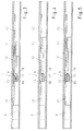
- the representation according to 2A and 2B represent the closed position of the door leaf 3 and 4 of the door 2 according to FIG. 1.
- both sliders 9 and 11 are in their starting position and the release rod 12 presses the pinch roller 8 out of it Locked position.
- the slider 11 of the passive leaf 3 is in this position the slider 9 of the active leaf 3 and thus the active leaf 3 itself free movable. If the active leaf 3 is opened, it can be without the Normally, closing sequence control 1 to be actuated because of the release rod 12 prevents the clamping rod 15 from becoming jammed by the locking member 8.
- the locking member 8 follows due to the action of the compression spring the release rod until the locking member 8 is in its clamping position, in which there is no longer any contact between the release rod 12 and the locking member 8 exists.
- the slider 11 also has Push member 12 on.
- the trigger rod 12 in turn has a tip 16 on with the locking member 8 mounted in the base body 13 again in and can be disengaged.
- the trigger rod 12 is also in the Base body 13 inserted and the tip 16 is preferably beveled.
- the locking member 8 is always biased towards its locking position.
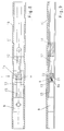
- FIG. 8 shows a longitudinal section and FIG. 9 shows a partial top view Sectional view.
- a holder 21 is arranged in which the locking member 8 is embedded movably.
- the holder 21 is partially excluded and on two of its three circumferential sides parallel to the long sides of the Slide rail 10 with elongated holes extending at a certain angle 22 provided.
- the locking member 8 is again preferably performed in the form of a pinch roller.
- the pinch roller 8 in turn is biased into its locked position by means of the spring element 8a. In this locking position is the pinch roller 8 with a friction surface 14 on one assigned surface area of the clamping rod 15 of the slider 9 on.
- the locking member 8 is always in its end position, which the locking or Clamp position corresponds to, pre-tensioned.
- the Clamping rod 15 arranged in the illustrated embodiment can also pass through the slider 11.
- the locking member 8 forms a clamping rod 15 Effective pairing.
- the push rod 12 forming the trigger rod of the slider 11 also passes through the base body 13 or the holder 17 and can release the clamping of the clamping rod 15, so that the active pairing interrupted between the locking member 8 and the clamping rod 15 can be.
- the slider 9 is the Active leaf and thus the active leaf 4 itself can move freely. Will the Active leaf 4 opened, this can be operated without the closing sequence controller be closed as normal, since the trigger rod 12 is stuck the clamping rod 15 prevented by the locking member 8.
- the passive leaf 3 is opened, removes the slider 11 from a zero position and thus the trigger rod 12 from the locking member 8.
- the locking member or the pinch roller 8 follows the release rod 12, due to the action of the compression spring 8a the locking member 8 is in its locked position, in which no contact there is more between the release rod 12 and the locking member 8.
Landscapes
- Power-Operated Mechanisms For Wings (AREA)
- Special Wing (AREA)
- Catalysts (AREA)
- Lasers (AREA)
- Closing And Opening Devices For Wings, And Checks For Wings (AREA)
- Wing Frames And Configurations (AREA)
- Glass Compositions (AREA)
Abstract
Description
- Figur 1:
- Eine zweiflügelige Tür mit einem Schließfolgeregler und jedem Türflügel zugehörigen Obentürschließern, in einer schematischen, perspektivischen Ansicht und
- Figur 2 - 7:
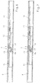
- schematisch stark vereinfachte Darstellungen eines Teiles des erfindungsgemäßen Schließfolgereglers im Bereich einer Gleitführung mit einem Sperrglied zur Erläuterung des Aufbaues und der Funktionsweise in unterschiedlichen Stellungen des Gang- und Standflügels in einer ersten Ausführungsform.
- Figur 8 - 14:
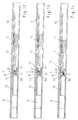
- eine zweite Ausführungsform eines erfindungsgemäßen Schließfolgereglers mit einem weiteren Sperrglied.
- 1
- Schließfolgeregler
- 2
- Tür
- 3
- Standflügel
- 4
- Gangflügel
- 5, 6
- Schwenkarm
- 7
- Türrahmen
- 8
- Sperrglied
- 8a
- Federelement
- 9
- Gleitstück
- 10
- Gleitführung
- 11
- Gleitstück
- 12
- Schubglied
- 13
- Grundkörper
- 14
- Reibfläche
- 15
- Klemmstange
- 16
- Spitze
- 17
- Klemmbügel
- 18
- Auflaufschräge
- 19, 20
- Türschließer
- 21
- Halter
- 22
- Langlöcher
Claims (17)
- Schließfolgeregler (1) für eine einen Standflügel (3) und einen Gangflügel (4) umfassende Tür (2), insbesondere Feuerschutztür, die über je einen Schwenkarm (5, 6) mit einem Türrahmen (7) verbunden sind, wobei der Schwenkarm (6) des Gangflügels (4) mittels eines vom Standflügel (3) freigebbaren Sperrgliedes (8) feststellbar ist,mit einem ersten Gleitstück (9), das mit einem türrahmenseitigen Ende des Schwenkarmes (6) des Gangflügels (4) verbunden ist und das in einer im/oder am Türrahmen (7) angebrachten Gleitführung (10) verschiebbar ist, undmit einem zweiten Gleitstück (11), das mit einem türrahmenseitigen Ende des Schwenkarmes (5) des Standflügels (3) verbunden ist, das in der Gleitführung (10) verschiebbar ist und das ein mit dem Sperrglied (8) in und außer Eingriff bringbares Schubglied (12) aufweist, dadurch gekennzeichet,dass das Sperrglied (8) in Richtung auf seine Sperrstellung vorgespannt ist.
- Schließfolgeregler nach Anspruch 1, dadurch gekennzeichnet, dass das Sperrglied (8) durch ein Federelement (8a) vorgespannt ist.
- Schließfolgeregler nach Anspruch 2, dadurch gekennzeichnet, dass das Federelement (8a) als Druckfeder, vorzugsweise Schraubenfeder, ausgebildet ist.
- Schließfolgeregler nach einem der Ansprüche 1 bis 3, dadurch gekennzeichnet, dass das Sperrglied (8) in einem Grundkörper (13) gelagert ist, der in der Gleitführung (10) fixierbar ist.
- Schließfolgeregler nach einem der Ansprüche 1 bis 4, dadurch gekennzeichnet, dass das Sperrglied (8) als Klemmrolle ausgebildet ist, das eine Reibfläche (14) aufweist.
- Schließfolgeregler nach einem der Ansprüche 4 oder 5, dadurch gekennzeichnet, dass das Gleitstück (9) des Gangflügels (4) eine Klemmstange (15) aufweist, die durch den Grundkörper (13) hindurch geführt ist und mit der das Sperrglied (8) zusammenwirkt.
- Schließfolgeregler nach einem der Ansprüche 1 bis 6, dadurch gekennzeichnet, dass das Schubglied (12) als Auslösestange ausgebildet ist, deren Spitze (16) mit dem Sperrglied (8) in und außer Eingriff bringbar ist.
- Schließfolgeregler nach Anspruch 7, dadurch gekennzeichnet, dass die Auslösestange (12) in dem Grundkörper (13) geführt ist.
- Schließfolgeregler nach einem der Ansprüche 7 oder 8, dadurch gekennzeichnet, dass die Spitze (16) angeschrägt ist.
- Schließfolgeregler nach einem der Ansprüche 1 bis 9, dadurch gekennzeichnet, dass das Sperrglied (8) in einem Klemmbügel (17) angeordnet ist, der am Grundkörper (13) fixiert ist.
- Schließfolgeregler nach Anspruch 10, dadurch gekennzeichnet, dass der Klemmbügel (17) biegeelastisch ist.
- Schließfolgeregler nach Anspruch 10 oder 11, dadurch gekennzeichnet, dass der Klemmbügel (17) nach Art eines Kragträgers ausgebildet ist.
- Schließfolgeregler nach einem der Ansprüche 10 bis 12, dadurch gekennzeichnet, dass der Klemmbügel (17) zur Seite des Gleitstückes (11) des Standflügels (3) in Richtung auf die Klemmstange (15) zur Bildung einer Auflaufschräge (18) abgewinkelt ist.
- Schließfolgeregler nach einem der Ansprüche 1 bis 9, dadurch gekennzeichnet, dass das Sperrglied (8) in einem Halter (21) angeordnet ist, der am Grundkörper (13) fixiert ist.
- Schließfolgeregler nach Anspruch 14, dadurch gekennzeichnet, dass der Halter (21) zwei Langlöcher (22) zur Führung des Sperrgliedes (8) aufweist.
- Schließfolgeregler nach Anspruch 15, dadurch gekennzeichnet, dass die Langlöcher (22) an zwei der drei Umfangsseiten des Halters (21) parallel zu den Längsseiten der Gleitführung (10) angeordnet sind.
- Schließfolgeregler nach einem der Ansprüche 14 bis 16, dadurch gekennzeichnet, dass der Halter (21) zur Seite des Gleitstückes (11) des Standflügels (3) in Richtung auf die Klemmstange (15) ausgenommen ist.
Applications Claiming Priority (4)
| Application Number | Priority Date | Filing Date | Title |
|---|---|---|---|
| DE10107888 | 2001-02-16 | ||
| DE10107886 | 2001-02-16 | ||
| DE10107888A DE10107888B4 (de) | 2001-02-16 | 2001-02-16 | Schließfolgeregler |
| DE10107886A DE10107886B4 (de) | 2001-02-16 | 2001-02-16 | Schließfolgeregler |
Publications (3)
| Publication Number | Publication Date |
|---|---|
| EP1233131A2 true EP1233131A2 (de) | 2002-08-21 |
| EP1233131A3 EP1233131A3 (de) | 2005-01-19 |
| EP1233131B1 EP1233131B1 (de) | 2006-12-27 |
Family
ID=26008560
Family Applications (1)
| Application Number | Title | Priority Date | Filing Date |
|---|---|---|---|
| EP02003436A Expired - Lifetime EP1233131B1 (de) | 2001-02-16 | 2002-02-14 | Schliessfolgeregler |
Country Status (4)
| Country | Link |
|---|---|
| EP (1) | EP1233131B1 (de) |
| AT (1) | ATE349595T1 (de) |
| DE (1) | DE50209041D1 (de) |
| DK (1) | DK1233131T3 (de) |
Citations (1)
| Publication number | Priority date | Publication date | Assignee | Title |
|---|---|---|---|---|
| DE3336739C2 (de) | 1983-10-08 | 1988-01-28 | Dorma Gmbh + Co Kg, 5828 Ennepetal, De |
Family Cites Families (3)
| Publication number | Priority date | Publication date | Assignee | Title |
|---|---|---|---|---|
| DE19545401A1 (de) * | 1995-12-06 | 1997-06-12 | Geze Gmbh & Co | Schließfolgesteuerung für eine zweiflügelige Tür |
| ES2195673B1 (es) * | 1999-12-24 | 2005-11-01 | Telesco Comercial 2000, S.L. | Selector mejorado de cierre para cierrapuertas en puertas de dos hojas. |
| FI107634B (fi) * | 2000-02-18 | 2001-09-14 | Abloy Oy | Ovensulkemisjärjestely pariovia varten |
-
2002
- 2002-02-14 DK DK02003436T patent/DK1233131T3/da active
- 2002-02-14 DE DE50209041T patent/DE50209041D1/de not_active Expired - Lifetime
- 2002-02-14 AT AT02003436T patent/ATE349595T1/de not_active IP Right Cessation
- 2002-02-14 EP EP02003436A patent/EP1233131B1/de not_active Expired - Lifetime
Patent Citations (1)
| Publication number | Priority date | Publication date | Assignee | Title |
|---|---|---|---|---|
| DE3336739C2 (de) | 1983-10-08 | 1988-01-28 | Dorma Gmbh + Co Kg, 5828 Ennepetal, De |
Also Published As
| Publication number | Publication date |
|---|---|
| DE50209041D1 (de) | 2007-02-08 |
| DK1233131T3 (da) | 2007-05-07 |
| EP1233131A3 (de) | 2005-01-19 |
| EP1233131B1 (de) | 2006-12-27 |
| ATE349595T1 (de) | 2007-01-15 |
Similar Documents
| Publication | Publication Date | Title |
|---|---|---|
| EP1247930B1 (de) | Vorrichtung zur Arretierung von in Schienen geführten Laufwerken | |
| DE3336739C2 (de) | ||
| DE102007033451B4 (de) | Überhub-Türschließvorrichtung für ein elektrisches Haushaltsgerät | |
| AT519593B1 (de) | Verriegelungsvorrichtung | |
| EP2354402A2 (de) | Verriegelung für Flügelanlagen | |
| DE102004011880A1 (de) | Schließblech für Fenster oder Fenstertüren | |
| EP2957697A1 (de) | Einzugsvorrichtung für Schiebetüren und Fenster oder Tür | |
| EP0152791B1 (de) | Stellvorrichtung für Schiebeflügel von Fenstern, Türen od. dgl. | |
| WO2015003872A1 (de) | Beschlag für ein fenster, eine tür oder dergleichen mit einem kipp- und schiebbaren flügel | |
| EP3034728B1 (de) | Öffnungsbegrenzereinrichtung | |
| EP2843169A1 (de) | Tragsystem für eine Schiebetür, sowie Schiebetür | |
| DE29500910U1 (de) | Schließfolgeregler | |
| EP0846825B1 (de) | Verriegelungsvorrichtung für ein in einer Zarge bewegbares Tür- oder Torblatt | |
| EP1233131B1 (de) | Schliessfolgeregler | |
| EP3192951B1 (de) | Beschlag für eine schiebetür, schiebetüreinheit, verfahren zum öffnen einer schiebetür und verfahren zum schliessen einer schiebetür | |
| DE10107886B4 (de) | Schließfolgeregler | |
| DE10107785B4 (de) | Schließfolgeregeler | |
| DE10107888B4 (de) | Schließfolgeregler | |
| EP1233133A2 (de) | Schliessfolgeregler | |
| DE102018202813B3 (de) | Mechanischer Auslöser | |
| EP1703061A2 (de) | Schliessfolgeregler | |
| DE10107884B4 (de) | Schließfolgeregler | |
| DE10360036B4 (de) | Vorrichtung zur Schließfolgeregelung | |
| DE10107787A1 (de) | Schließfolgeregler | |
| DE10152676B4 (de) | Schließfolgeregler |
Legal Events
| Date | Code | Title | Description |
|---|---|---|---|
| PUAI | Public reference made under article 153(3) epc to a published international application that has entered the european phase |
Free format text: ORIGINAL CODE: 0009012 |
|
| AK | Designated contracting states |
Kind code of ref document: A2 Designated state(s): AT BE CH CY DE DK ES FI FR GB GR IE IT LI LU MC NL PT SE TR |
|
| AX | Request for extension of the european patent |
Free format text: AL;LT;LV;MK;RO;SI |
|
| PUAL | Search report despatched |
Free format text: ORIGINAL CODE: 0009013 |
|
| AK | Designated contracting states |
Kind code of ref document: A3 Designated state(s): AT BE CH CY DE DK ES FI FR GB GR IE IT LI LU MC NL PT SE TR |
|
| AX | Request for extension of the european patent |
Extension state: AL LT LV MK RO SI |
|
| 17P | Request for examination filed |
Effective date: 20050719 |
|
| AKX | Designation fees paid |
Designated state(s): AT BE CH CY DE DK ES FI FR GB GR IE IT LI LU MC NL PT SE TR |
|
| GRAP | Despatch of communication of intention to grant a patent |
Free format text: ORIGINAL CODE: EPIDOSNIGR1 |
|
| GRAS | Grant fee paid |
Free format text: ORIGINAL CODE: EPIDOSNIGR3 |
|
| GRAA | (expected) grant |
Free format text: ORIGINAL CODE: 0009210 |
|
| STAA | Information on the status of an ep patent application or granted ep patent |
Free format text: STATUS: THE PATENT HAS BEEN GRANTED |
|
| AK | Designated contracting states |
Kind code of ref document: B1 Designated state(s): AT BE CH CY DE DK ES FI FR GB GR IE IT LI LU MC NL PT SE TR |
|
| PG25 | Lapsed in a contracting state [announced via postgrant information from national office to epo] |
Ref country code: NL Free format text: LAPSE BECAUSE OF FAILURE TO SUBMIT A TRANSLATION OF THE DESCRIPTION OR TO PAY THE FEE WITHIN THE PRESCRIBED TIME-LIMIT Effective date: 20061227 |
|
| REG | Reference to a national code |
Ref country code: GB Ref legal event code: FG4D Free format text: NOT ENGLISH |
|
| REG | Reference to a national code |
Ref country code: IE Ref legal event code: FG4D Free format text: LANGUAGE OF EP DOCUMENT: GERMAN |
|
| REF | Corresponds to: |
Ref document number: 50209041 Country of ref document: DE Date of ref document: 20070208 Kind code of ref document: P |
|
| PGFP | Annual fee paid to national office [announced via postgrant information from national office to epo] |
Ref country code: AT Payment date: 20070213 Year of fee payment: 6 Ref country code: SE Payment date: 20070213 Year of fee payment: 6 |
|
| PGFP | Annual fee paid to national office [announced via postgrant information from national office to epo] |
Ref country code: CH Payment date: 20070214 Year of fee payment: 6 Ref country code: DK Payment date: 20070214 Year of fee payment: 6 Ref country code: FI Payment date: 20070214 Year of fee payment: 6 |
|
| PGFP | Annual fee paid to national office [announced via postgrant information from national office to epo] |
Ref country code: GB Payment date: 20070216 Year of fee payment: 6 |
|
| PGFP | Annual fee paid to national office [announced via postgrant information from national office to epo] |
Ref country code: IE Payment date: 20070220 Year of fee payment: 6 |
|
| PGFP | Annual fee paid to national office [announced via postgrant information from national office to epo] |
Ref country code: ES Payment date: 20070227 Year of fee payment: 6 |
|
| PG25 | Lapsed in a contracting state [announced via postgrant information from national office to epo] |
Ref country code: MC Free format text: LAPSE BECAUSE OF NON-PAYMENT OF DUE FEES Effective date: 20070228 |
|
| REG | Reference to a national code |
Ref country code: CH Ref legal event code: NV Representative=s name: BOVARD AG PATENTANWAELTE |
|
| GBT | Gb: translation of ep patent filed (gb section 77(6)(a)/1977) |
Effective date: 20070307 |
|
| REG | Reference to a national code |
Ref country code: SE Ref legal event code: TRGR |
|
| REG | Reference to a national code |
Ref country code: DK Ref legal event code: T3 |
|
| PG25 | Lapsed in a contracting state [announced via postgrant information from national office to epo] |
Ref country code: PT Free format text: LAPSE BECAUSE OF FAILURE TO SUBMIT A TRANSLATION OF THE DESCRIPTION OR TO PAY THE FEE WITHIN THE PRESCRIBED TIME-LIMIT Effective date: 20070528 |
|
| NLV1 | Nl: lapsed or annulled due to failure to fulfill the requirements of art. 29p and 29m of the patents act | ||
| ET | Fr: translation filed | ||
| BERE | Be: lapsed |
Owner name: DORMA G.M.B.H. + CO. KG Effective date: 20070228 |
|
| PG25 | Lapsed in a contracting state [announced via postgrant information from national office to epo] |
Ref country code: BE Free format text: LAPSE BECAUSE OF NON-PAYMENT OF DUE FEES Effective date: 20070228 |
|
| PG25 | Lapsed in a contracting state [announced via postgrant information from national office to epo] |
Ref country code: GR Free format text: LAPSE BECAUSE OF FAILURE TO SUBMIT A TRANSLATION OF THE DESCRIPTION OR TO PAY THE FEE WITHIN THE PRESCRIBED TIME-LIMIT Effective date: 20070328 |
|
| PGFP | Annual fee paid to national office [announced via postgrant information from national office to epo] |
Ref country code: FR Payment date: 20070212 Year of fee payment: 6 |
|
| REG | Reference to a national code |
Ref country code: DK Ref legal event code: EBP |
|
| REG | Reference to a national code |
Ref country code: CH Ref legal event code: PL |
|
| EUG | Se: european patent has lapsed | ||
| GBPC | Gb: european patent ceased through non-payment of renewal fee |
Effective date: 20080214 |
|
| PG25 | Lapsed in a contracting state [announced via postgrant information from national office to epo] |
Ref country code: LI Free format text: LAPSE BECAUSE OF NON-PAYMENT OF DUE FEES Effective date: 20080229 Ref country code: CH Free format text: LAPSE BECAUSE OF NON-PAYMENT OF DUE FEES Effective date: 20080229 Ref country code: FI Free format text: LAPSE BECAUSE OF NON-PAYMENT OF DUE FEES Effective date: 20080314 |
|
| PG25 | Lapsed in a contracting state [announced via postgrant information from national office to epo] |
Ref country code: AT Free format text: LAPSE BECAUSE OF NON-PAYMENT OF DUE FEES Effective date: 20080214 |
|
| REG | Reference to a national code |
Ref country code: FR Ref legal event code: ST Effective date: 20081031 |
|
| PG25 | Lapsed in a contracting state [announced via postgrant information from national office to epo] |
Ref country code: DK Free format text: LAPSE BECAUSE OF NON-PAYMENT OF DUE FEES Effective date: 20080229 Ref country code: IE Free format text: LAPSE BECAUSE OF NON-PAYMENT OF DUE FEES Effective date: 20080214 Ref country code: SE Free format text: LAPSE BECAUSE OF NON-PAYMENT OF DUE FEES Effective date: 20080215 |
|
| PG25 | Lapsed in a contracting state [announced via postgrant information from national office to epo] |
Ref country code: FR Free format text: LAPSE BECAUSE OF NON-PAYMENT OF DUE FEES Effective date: 20080229 |
|
| PG25 | Lapsed in a contracting state [announced via postgrant information from national office to epo] |
Ref country code: GB Free format text: LAPSE BECAUSE OF NON-PAYMENT OF DUE FEES Effective date: 20080214 |
|
| PG25 | Lapsed in a contracting state [announced via postgrant information from national office to epo] |
Ref country code: LU Free format text: LAPSE BECAUSE OF NON-PAYMENT OF DUE FEES Effective date: 20070214 Ref country code: CY Free format text: LAPSE BECAUSE OF FAILURE TO SUBMIT A TRANSLATION OF THE DESCRIPTION OR TO PAY THE FEE WITHIN THE PRESCRIBED TIME-LIMIT Effective date: 20061227 |
|
| PG25 | Lapsed in a contracting state [announced via postgrant information from national office to epo] |
Ref country code: TR Free format text: LAPSE BECAUSE OF FAILURE TO SUBMIT A TRANSLATION OF THE DESCRIPTION OR TO PAY THE FEE WITHIN THE PRESCRIBED TIME-LIMIT Effective date: 20061227 Ref country code: IT Free format text: LAPSE BECAUSE OF NON-PAYMENT OF DUE FEES Effective date: 20070214 |
|
| PG25 | Lapsed in a contracting state [announced via postgrant information from national office to epo] |
Ref country code: ES Free format text: LAPSE BECAUSE OF THE APPLICANT RENOUNCES Effective date: 20070418 |
|
| PGFP | Annual fee paid to national office [announced via postgrant information from national office to epo] |
Ref country code: DE Payment date: 20140219 Year of fee payment: 13 |
|
| REG | Reference to a national code |
Ref country code: DE Ref legal event code: R081 Ref document number: 50209041 Country of ref document: DE Owner name: DORMA DEUTSCHLAND GMBH, DE Free format text: FORMER OWNER: DORMA GMBH + CO. KG, 58256 ENNEPETAL, DE Effective date: 20150224 |
|
| REG | Reference to a national code |
Ref country code: DE Ref legal event code: R119 Ref document number: 50209041 Country of ref document: DE |
|
| PG25 | Lapsed in a contracting state [announced via postgrant information from national office to epo] |
Ref country code: DE Free format text: LAPSE BECAUSE OF NON-PAYMENT OF DUE FEES Effective date: 20150901 |