EP1232970A1 - Device for unloading stacks of thermoformed objects from a receiving cage to a removing conveyor - Google Patents
Device for unloading stacks of thermoformed objects from a receiving cage to a removing conveyor Download PDFInfo
- Publication number
- EP1232970A1 EP1232970A1 EP02003119A EP02003119A EP1232970A1 EP 1232970 A1 EP1232970 A1 EP 1232970A1 EP 02003119 A EP02003119 A EP 02003119A EP 02003119 A EP02003119 A EP 02003119A EP 1232970 A1 EP1232970 A1 EP 1232970A1
- Authority
- EP
- European Patent Office
- Prior art keywords
- stacks
- support plate
- cage
- conveyer
- thermoformed
- Prior art date
- Legal status (The legal status is an assumption and is not a legal conclusion. Google has not performed a legal analysis and makes no representation as to the accuracy of the status listed.)
- Withdrawn
Links
Images
Classifications
-
- B—PERFORMING OPERATIONS; TRANSPORTING
- B29—WORKING OF PLASTICS; WORKING OF SUBSTANCES IN A PLASTIC STATE IN GENERAL
- B29C—SHAPING OR JOINING OF PLASTICS; SHAPING OF MATERIAL IN A PLASTIC STATE, NOT OTHERWISE PROVIDED FOR; AFTER-TREATMENT OF THE SHAPED PRODUCTS, e.g. REPAIRING
- B29C51/00—Shaping by thermoforming, i.e. shaping sheets or sheet like preforms after heating, e.g. shaping sheets in matched moulds or by deep-drawing; Apparatus therefor
- B29C51/26—Component parts, details or accessories; Auxiliary operations
- B29C51/44—Removing or ejecting moulded articles
-
- B—PERFORMING OPERATIONS; TRANSPORTING
- B65—CONVEYING; PACKING; STORING; HANDLING THIN OR FILAMENTARY MATERIAL
- B65G—TRANSPORT OR STORAGE DEVICES, e.g. CONVEYORS FOR LOADING OR TIPPING, SHOP CONVEYOR SYSTEMS OR PNEUMATIC TUBE CONVEYORS
- B65G47/00—Article or material-handling devices associated with conveyors; Methods employing such devices
- B65G47/74—Feeding, transfer, or discharging devices of particular kinds or types
- B65G47/82—Rotary or reciprocating members for direct action on articles or materials, e.g. pushers, rakes, shovels
-
- B—PERFORMING OPERATIONS; TRANSPORTING
- B65—CONVEYING; PACKING; STORING; HANDLING THIN OR FILAMENTARY MATERIAL
- B65G—TRANSPORT OR STORAGE DEVICES, e.g. CONVEYORS FOR LOADING OR TIPPING, SHOP CONVEYOR SYSTEMS OR PNEUMATIC TUBE CONVEYORS
- B65G47/00—Article or material-handling devices associated with conveyors; Methods employing such devices
- B65G47/74—Feeding, transfer, or discharging devices of particular kinds or types
- B65G47/90—Devices for picking-up and depositing articles or materials
- B65G47/902—Devices for picking-up and depositing articles or materials provided with drive systems incorporating rotary and rectilinear movements
-
- B—PERFORMING OPERATIONS; TRANSPORTING
- B29—WORKING OF PLASTICS; WORKING OF SUBSTANCES IN A PLASTIC STATE IN GENERAL
- B29C—SHAPING OR JOINING OF PLASTICS; SHAPING OF MATERIAL IN A PLASTIC STATE, NOT OTHERWISE PROVIDED FOR; AFTER-TREATMENT OF THE SHAPED PRODUCTS, e.g. REPAIRING
- B29C31/00—Handling, e.g. feeding of the material to be shaped, storage of plastics material before moulding; Automation, i.e. automated handling lines in plastics processing plants, e.g. using manipulators or robots
-
- B—PERFORMING OPERATIONS; TRANSPORTING
- B29—WORKING OF PLASTICS; WORKING OF SUBSTANCES IN A PLASTIC STATE IN GENERAL
- B29C—SHAPING OR JOINING OF PLASTICS; SHAPING OF MATERIAL IN A PLASTIC STATE, NOT OTHERWISE PROVIDED FOR; AFTER-TREATMENT OF THE SHAPED PRODUCTS, e.g. REPAIRING
- B29C37/00—Component parts, details, accessories or auxiliary operations, not covered by group B29C33/00 or B29C35/00
- B29C37/0003—Discharging moulded articles from the mould
- B29C37/0007—Discharging moulded articles from the mould using means operable from outside the mould for moving between mould parts, e.g. robots
-
- B—PERFORMING OPERATIONS; TRANSPORTING
- B29—WORKING OF PLASTICS; WORKING OF SUBSTANCES IN A PLASTIC STATE IN GENERAL
- B29C—SHAPING OR JOINING OF PLASTICS; SHAPING OF MATERIAL IN A PLASTIC STATE, NOT OTHERWISE PROVIDED FOR; AFTER-TREATMENT OF THE SHAPED PRODUCTS, e.g. REPAIRING
- B29C51/00—Shaping by thermoforming, i.e. shaping sheets or sheet like preforms after heating, e.g. shaping sheets in matched moulds or by deep-drawing; Apparatus therefor
- B29C51/26—Component parts, details or accessories; Auxiliary operations
- B29C51/261—Handling means, e.g. transfer means, feeding means
-
- B—PERFORMING OPERATIONS; TRANSPORTING
- B29—WORKING OF PLASTICS; WORKING OF SUBSTANCES IN A PLASTIC STATE IN GENERAL
- B29L—INDEXING SCHEME ASSOCIATED WITH SUBCLASS B29C, RELATING TO PARTICULAR ARTICLES
- B29L2031/00—Other particular articles
- B29L2031/712—Containers; Packaging elements or accessories, Packages
-
- B—PERFORMING OPERATIONS; TRANSPORTING
- B29—WORKING OF PLASTICS; WORKING OF SUBSTANCES IN A PLASTIC STATE IN GENERAL
- B29L—INDEXING SCHEME ASSOCIATED WITH SUBCLASS B29C, RELATING TO PARTICULAR ARTICLES
- B29L2031/00—Other particular articles
- B29L2031/712—Containers; Packaging elements or accessories, Packages
- B29L2031/7132—Bowls, Cups, Glasses
Definitions
- the present invention regards a plant for unloading stacks of thermoformed products from a stack receiving cage onto a removing conveyer.
- thermoformed objects in this description and in the claims, it is meant hollow packaging products, typically, lids and containers, e. g. drinking cups, coffee cups, dessert cups, tubs, plates, trays and the like.
- an discharge or unloading plant or system is made up of a support structure or upright 2, which bears overhead a support plate (3) for a receiving cage 4 of stacks 5 of thermoformed objects or products.
- the support plate 3 is formed with a plurality of through openings or slots 6 (Fig. 2) at each stack or row of stacks 5 and is mounted for rotation around a horizontal axis x-x on the upright 2 through a support head 7 rotatable about the axis x-x- and provided with a reversible electric drive motor 8 which carries out angular programmed movements of preset width.
- the support plate 3 and the cage 4 brought by it are therefore angularly movable between an erect position, in which the cage 4 can be loaded in any suitable way with a multiplicity of stacks 5 of vertical thermoformed products, and an inclined discharge position.
- a product expeller device e. g. comprising a support stand 11, and a transverse expulsion bar 12 at the head of a plurality of rods 13 driven at the other side thereof by a double-acting pneumatic jack 14 and slidably supported on the stand 11.
- the bar 12 is arranged to pass through the slot 6 or slots 6 in the support plate 3, once the latter has been brought into its inclined unloading position, to expel a complete row of stacks 5 of thermoformed products from the cage 4 and discharge them onto a taking away conveyer 20.
- the conveyer 20 Above and parallel to the direction of movement of the conveyer 20 there are two moving guides: one 25 at the side of the conveyer close to the plate 3 and the other 26 on the opposite side, which extends for the whole length of the conveyer, while the guide 25 terminates at the cage 4 so as not to hinder the passage of the stacks 5 as they are expelled from the cage 4.
- the guides 25 and 26 prevent the decomposition of the stacks 5, as shown in Fig. 4, when they are loaded on the conveyer 20.
- the expulsion bar 12 acts as a sliding guide, and remains in a co-planar position with the guide 25 until the tape of conveyer 20 is not sufficiently advanced so that all the stacks slidingly abut against the bar 20.
- the guide 26 can be adjustably positioned with respect to the guide 25, e.g. by means of overhanging supports 27 and locking clamps 27a.
- the conveyer belt can have transverse partitions 28, which extend parallel to and uniformly spaced from 28 to delimit receiving cradles for the stacks 5, thereby keeping them in constant axial alignment .
- the cage 4 is loaded with stacks 5 of thermoformed products by a transfer device 30, e. g. of the rotating arm type, which can raise-lower to pick up and unload (total or partial) stacks 5 of thermoformed products from a stacking station 31 located at a rotating conveyer 32, for example with four radial template-carrying arms for transporting and stacking themoformed products.
- a transfer device 30 e. g. of the rotating arm type, which can raise-lower to pick up and unload (total or partial) stacks 5 of thermoformed products from a stacking station 31 located at a rotating conveyer 32, for example with four radial template-carrying arms for transporting and stacking themoformed products.
Landscapes
- Engineering & Computer Science (AREA)
- Mechanical Engineering (AREA)
- Specific Conveyance Elements (AREA)
- Attitude Control For Articles On Conveyors (AREA)
- Butt Welding And Welding Of Specific Article (AREA)
Abstract
Description
- The present invention regards a plant for unloading stacks of thermoformed products from a stack receiving cage onto a removing conveyer.
- With the expression "thermoformed objects" in this description and in the claims, it is meant hollow packaging products, typically, lids and containers, e. g. drinking cups, coffee cups, dessert cups, tubs, plates, trays and the like.
- Unloading and handling in general of a plurality of stacks of thermoformed objects is often problematical as the passage from one transfer support to another needs constant surveillance to ensure the perfect axial alignment of the stacks and it is necessary that the various products forming each stack are kept compact to avoid the disintegration of the stacks, which may occur for example with shallow containers, such as lids and plates, which can be a source of problems and difficulties in successive handling operations, e. g. during the de-stacking of these products, for example in an automatic de-stacking machine.
- The main object of the present invention is to provide a plant for unloading or discharging a plurality of parallel stacks of thermoformed products from a containing crate or cage to another support, which makes it possible to change the orientation direction of the stacks, whilst keeping these compact and in perfect axial arrangement.
- Another object of the present invention is that the said unloading plant or system permits the graduated and sequential discharge of a pre-established number of stacks at a time until all the stacks in a containing cage have been discharged.
- Yet another object of the present invention is that the said discharge plant is of a high efficiency and can operate in step and in synchronisation with a thermoformed products stacking line downstream of a single station thermoforming machine or press with form and cut mould.
- These and other objects, which will be better appear below, are attained by a plant for unloading stacks of thermoformed products starting from a stack containing cage, which includes a support structure, at least one supporting plate for a respective stack containing cage, that is mounted for rotation on said support structure, drive means arranged to cause the said support plate angular excursions of predetermined amplitude around a horizontal axis, thereby angularly moving a respective stack containing cage between an erect position, in which the stacks of thermoformed objects contained therein extend in a substantially vertical direction, and an inclined discharge position, expeller means for expelling stacks of thermoformed products from said support plate when said support plate is in an inclined discharge position, and a receiving conveyer for the stacks of thermoformed products unloaded from said containing cage located downstream of the discharging position of said support plate.
- Advantageously, the plant includes drive means to vertically move said support plate between a plurality of discharge positions to unload groups of stacks of thermoformed objects onto said receiving conveyer at different levels. Moreover, said receiving conveyer is inclinable substantially at the same angle of inclination as said support plate in its inclined discharge position.
- Further aspects and advantages of the present invention will better appear in the following detailed description of some currently preferred embodiments, given as illustrative and not limiting examples with reference to accompanying drawings, in which :
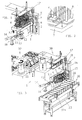
- Figure 1 is a front view of a plant according to the present invention, without (for illustrative purposes) a taking away conveyer;
- Figure 2 shows a detail on an enlarged scale of a support plate of a receiving crate for stacks of thermoformed objects;
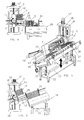
- Figure 3 shows a complete plant according to the present invention with a taking away conveyer arranged in horizontal attitude;
- Figure 4 shows a diagrammatic and partial front view of a handling plant according to the present invention, with expeller means acting horizontally;
- Figure 5 shows a plant according to the present invention with taking away conveyer in inclined attitude and while receiving stacks of thermoformed objects; and
- Figure 6 is a frontal diagrammatic view of the system of Fig. 5.
-
- With reference to the above Figures, it will be noted that as an discharge or unloading plant or system, generically indicated with 1, according to the present invention, is made up of a support structure or upright 2, which bears overhead a support plate (3) for a receiving
cage 4 ofstacks 5 of thermoformed objects or products. Thesupport plate 3 is formed with a plurality of through openings or slots 6 (Fig. 2) at each stack or row ofstacks 5 and is mounted for rotation around a horizontal axis x-x on the upright 2 through asupport head 7 rotatable about the axis x-x- and provided with a reversibleelectric drive motor 8 which carries out angular programmed movements of preset width. Thesupport plate 3 and thecage 4 brought by it are therefore angularly movable between an erect position, in which thecage 4 can be loaded in any suitable way with a multiplicity ofstacks 5 of vertical thermoformed products, and an inclined discharge position. - Beneath the
support plate 3 there is provided a product expeller device, e. g. comprising asupport stand 11, and atransverse expulsion bar 12 at the head of a plurality ofrods 13 driven at the other side thereof by a double-actingpneumatic jack 14 and slidably supported on thestand 11. Thebar 12 is arranged to pass through theslot 6 orslots 6 in thesupport plate 3, once the latter has been brought into its inclined unloading position, to expel a complete row ofstacks 5 of thermoformed products from thecage 4 and discharge them onto a taking awayconveyer 20. - Should the cage have several rows of
stacks 5, the turninghead 7 is mounted on aslide 15 slidably mounted onvertical guides 16 and driven to move up and down, upon control, by a reversibleelectric motor 17 which drives acontrol screw 18 meshing with a nut screw integral with, or secured to, the slide 15.With this structure, once a row ofstacks 5 has been expelled from the cage orcrate 4, theplate 3 is lowered to such an extent as to bring the adjacent row and successively, the remaining rows of stacks to the level of the taking awayconveyer 20. - The receiving and taking away
conveyer 20 for thestacks 5 of thermoformed products unloaded by theexpulsion bar 12 from the containingcrate 4 is of the belt type and is located downstream of the unloading position of thesupport plate 3 and, preferably, as better illustrated in Figures 5 and 6, it can be inclined at an angle of less than 90°, e. g. owing to the action of a couple ofpneumatic jacks 22, around an articulated horizontal axis, along which there are provided linkingpins 21 for articulation to anunderlying support frame 23. Preferably , the inclination of thebelt conveyer 20 is equal to that of the supportingplate 3 when in its discharging position. - Once complete unloading of the
cage 4 has taken place, theconveyer 20, preferably, takes again its horizontal attitude owing to the action of the jacks in order to be aligned with the standard position, for example of a packaging line ofstacks 5. - In Figure 4, there is illustrated a taking away
conveyer 20 in its horizontal attitude, which is fed withstacks 5 of thermoformed products by anexpulsion bar 12 driven byrods 13 also moving in a horizontal direction.. - Above and parallel to the direction of movement of the
conveyer 20 there are two moving guides: one 25 at the side of the conveyer close to theplate 3 and the other 26 on the opposite side, which extends for the whole length of the conveyer, while theguide 25 terminates at thecage 4 so as not to hinder the passage of thestacks 5 as they are expelled from thecage 4. Theguides stacks 5, as shown in Fig. 4, when they are loaded on theconveyer 20. During the unloading phase, at the missing section of theguide 25, theexpulsion bar 12 acts as a sliding guide, and remains in a co-planar position with theguide 25 until the tape ofconveyer 20 is not sufficiently advanced so that all the stacks slidingly abut against thebar 20. - Advantageously, the
guide 26 can be adjustably positioned with respect to theguide 25, e.g. by means of overhanging supports 27 and lockingclamps 27a. Moreover, the conveyer belt can havetransverse partitions 28, which extend parallel to and uniformly spaced from 28 to delimit receiving cradles for thestacks 5, thereby keeping them in constant axial alignment . - As can be seen in Fig. 3, the
cage 4 is loaded withstacks 5 of thermoformed products by atransfer device 30, e. g. of the rotating arm type, which can raise-lower to pick up and unload (total or partial)stacks 5 of thermoformed products from astacking station 31 located at a rotatingconveyer 32, for example with four radial template-carrying arms for transporting and stacking themoformed products. - The disclosure in Italian patent application no.VR2001A000018 filed on 15th February 2001 from which priority is claimed is incorporated herein by reference.
- Any reference sign following technical features in any claim has been provided to increase intelligibility of the claim and shall not be construed as limiting the scope of the claim.
Claims (9)
- A plant for unloading stacks (5) of thermoformed products from a cage (4) containing stacks (5), which comprises a support structure (2), at least one support plate (3) for a respective cage (4) containing stacks (5), which is mounted for rotation on said support structure (2), drive means (8) to cause said support platen (3) to effect angular movements of a preset amplitude around a horizontal axis, so as to angularly move its respective containing cage (4) between an erect position, in which the stacks (5) of thermoformed products contained therein extend in a substantially vertical direction, and an inclined unloading position, expeller means (12) designed to expel stacks (5) of thermoformed objects from said cage (4) when said support plate (3) is in inclined unloading position, and a conveyer (20) for receiving stacks (4) of thermoformed objects unloaded from said containing cage (4) located downstream of the unloading position of said support plate (3).
- A plant according to claim 1, characterized in that it comprises drive means (7,18) arranged to vertically move the said support plate (3) between a plurality of unloading positions to unload stacks (5) of thermoformed objects at different levels onto said receiving conveyer (20).
- A plant according to claim 1 or 2, characterized in that said receiving conveyer (20) is hinged about a horizontal axis and has actuating means (22) to arrange itself into inclined position substantially at the same angle of inclination as the said support plate (3 ) in its inclined unloading position.
- A plant according to any of the previous claim, characterized in that it comprises a couple of moving guides (25, 26) extending above and parallel to the direction of movement of said receiving conveyer (20) and spaced from one another by a distance substantially equal in length to the height of the stacks (4) to be transported.
- A plant according to claim 4, characterized in that the slide guide (25) next to the said support plate (3) is shorter than the other (26) by a length at the said support plate (3).
- A plant according to claim 4 or 5, characterized in that said pair of guides is spaced by an adjustable distance from each other.
- A plant according to any of the previous claim, characterized in that said receiving conveyer (20) has transverse and parallel partitions (28) for the stacks (5).
- A plant according to claim 7, characterized in that said receiving conveyer (20) takes, when loaded with stacks (5) of thermoformed objects, an attitude in accordance with to a handling system placed downstream of said taking away conveyer (20).
- A plant according to any of the previous claim, characterized in that it comprises in combination a device (30) for transferring stacks or portions of stacks (5, 5a, 5b), positioned upstream of said support plate (3), a stacking station (31) of thermoformed objects designed to feed the said transfer device (30), and a rotating conveyer (32) with several template-carrying radial arms for mouldings of thermoformed objects.
Applications Claiming Priority (2)
| Application Number | Priority Date | Filing Date | Title |
|---|---|---|---|
| ITVR010018 | 2001-02-15 | ||
| IT2001VR000018A ITVR20010018A1 (en) | 2001-02-15 | 2001-02-15 | STACKING SYSTEM OF STACKS OF THERMOFORMED OBJECTS FROM A WELDING CAGE TO A REMOVAL CONVEYOR |
Publications (1)
| Publication Number | Publication Date |
|---|---|
| EP1232970A1 true EP1232970A1 (en) | 2002-08-21 |
Family
ID=11461951
Family Applications (1)
| Application Number | Title | Priority Date | Filing Date |
|---|---|---|---|
| EP02003119A Withdrawn EP1232970A1 (en) | 2001-02-15 | 2002-02-13 | Device for unloading stacks of thermoformed objects from a receiving cage to a removing conveyor |
Country Status (3)
| Country | Link |
|---|---|
| US (1) | US6769856B2 (en) |
| EP (1) | EP1232970A1 (en) |
| IT (1) | ITVR20010018A1 (en) |
Cited By (5)
| Publication number | Priority date | Publication date | Assignee | Title |
|---|---|---|---|---|
| EP1731453A1 (en) * | 2005-06-09 | 2006-12-13 | Kiefel Ag | Method and device for stacking deep drawn articles |
| US20100189537A1 (en) * | 2007-06-26 | 2010-07-29 | Norbert Cottone | Device and method for transferring product stacks |
| EP2251181A1 (en) * | 2009-05-14 | 2010-11-17 | Gabler Thermoform GmbH & Co. KG | Device for stacking ready-made, thermoplastic articles |
| CN109720847A (en) * | 2017-10-30 | 2019-05-07 | 富鼎电子科技(嘉善)有限公司 | Take material drain system |
| DE102022107552A1 (en) | 2022-03-30 | 2023-10-05 | Ampack Gmbh | Container feeding device and method for feeding containers to a dosing and/or filling device |
Families Citing this family (13)
| Publication number | Priority date | Publication date | Assignee | Title |
|---|---|---|---|---|
| US20050279616A1 (en) * | 2004-06-18 | 2005-12-22 | Pogue Richard W | Extendible conveyor system |
| US9340362B2 (en) | 2011-07-07 | 2016-05-17 | Span Tech Llc | Conveyor with improved cleaning capabilities |
| ITBO20120307A1 (en) * | 2012-06-05 | 2013-12-06 | Marchesini Group Spa | FEEDING DEVICE FOR AN INPUT LINE OF A CASING MACHINE WITH COVERED CASES CONTAINED INSIDE A CARDBOARD, AND CARDBOARD PACKAGE CONTAINING OPENED CASES |
| EP3274151B1 (en) | 2015-03-23 | 2019-08-21 | WM Thermoforming Machines SA | Thermoforming machine and method |
| US10435252B1 (en) * | 2018-10-08 | 2019-10-08 | Becton Dickinson Rowa Germany Gmbh | Operating device for placing or retrieving bottle-like piece goods |
| US10889452B1 (en) * | 2018-10-30 | 2021-01-12 | Douglas Machine Inc. | Article accumulation and article group formation |
| CN109573171A (en) * | 2019-01-09 | 2019-04-05 | 杭州巧狮信息科技有限公司 | A kind of packing machine of combination bowl tool |
| DE102019104303A1 (en) * | 2019-02-20 | 2020-08-20 | Erca S.A.S. | Feed device for container parts for use on a device for filling containers with liquid to pasty foodstuffs |
| CN109720867A (en) * | 2019-02-22 | 2019-05-07 | 广东溢达纺织有限公司 | Shedding mechanism |
| US10954080B1 (en) * | 2019-10-08 | 2021-03-23 | Intelligrated Headquarters, Llc | Automatic conversion station |
| CN111761461B (en) * | 2020-06-18 | 2021-05-14 | 浙江凯迪汽车部件工业有限公司 | Automatic production line and process for inner ball cage retainer |
| CN114868813B (en) * | 2022-05-31 | 2023-12-22 | 厦门天辅星食品有限公司 | Production method and device of raw material black tea of milk tea |
| CN115057219B (en) * | 2022-06-23 | 2023-07-28 | 中南大学 | A kind of automatic stacking device for block type scrap steel |
Citations (3)
| Publication number | Priority date | Publication date | Assignee | Title |
|---|---|---|---|---|
| EP0810079A1 (en) * | 1996-05-28 | 1997-12-03 | Isap O.M.V. Group Spa | Apparatus for withdrawing and processing thermoformed objects from a thermoforming machine |
| EP0995582A2 (en) * | 1998-10-22 | 2000-04-26 | Gabler Maschinenbau GmbH | Thermo-forming machine |
| EP1075924A1 (en) * | 1999-07-16 | 2001-02-14 | Illig, Adolf Maschinenbau GmbH & Co. | Method and device for piling containers made of thermoplastic material |
Family Cites Families (13)
| Publication number | Priority date | Publication date | Assignee | Title |
|---|---|---|---|---|
| DE1432263A1 (en) | 1963-10-05 | 1968-11-28 | Thiel Alfons W | Container |
| US3491633A (en) | 1967-02-01 | 1970-01-27 | Brown Machine Co Of Michigan | Plastic container transfer apparatus and methods |
| GB1175879A (en) | 1967-08-15 | 1970-01-01 | Monsanto Chemicals | Moulding process for the production of containers |
| US3616951A (en) * | 1969-09-30 | 1971-11-02 | Owens Illinois Inc | Carton unloading and stack transferring apparatus |
| US3820496A (en) * | 1972-05-12 | 1974-06-28 | Fmc Corp | Conveyer feeder |
| US3773457A (en) | 1972-06-19 | 1973-11-20 | D Badoux | Apparatus for extracting, stacking and discharging moulded cups, jars and similar from moulding apparatus |
| DE3141514C1 (en) * | 1981-10-20 | 1983-07-21 | Gebhardt Fördertechnik GmbH, 6920 Sinsheim | Device for emptying containers loaded with stacked pieces |
| IT1183734B (en) | 1984-02-10 | 1987-10-22 | Omv Spa Off Mecc Veronese | FEMALE MOLD FOR STACKABLE CONTAINERS |
| JPH07110654B2 (en) * | 1988-06-17 | 1995-11-29 | 麒麟麦酒株式会社 | Container feeder |
| US5244330A (en) * | 1991-08-29 | 1993-09-14 | Custom Metal Designs, Inc. | Bottler loader and method |
| IT1257010B (en) | 1992-02-03 | 1996-01-05 | Omv Spa | PROCESS AND EQUIPMENT FOR THERMOFORMING AND STACKING OF CABLE OBJECTS WITH BOTTOM STARTING FROM THERMOPLASTIC TAPE MATERIAL. |
| DE19812414C2 (en) | 1998-03-20 | 2003-12-18 | Walter Lauermann | Receiving device for series products, in particular plastic cups |
| US6227357B1 (en) * | 1998-06-09 | 2001-05-08 | William L. Brown, Sr. | Air lift device |
-
2001
- 2001-02-15 IT IT2001VR000018A patent/ITVR20010018A1/en unknown
-
2002
- 2002-02-13 EP EP02003119A patent/EP1232970A1/en not_active Withdrawn
- 2002-02-14 US US10/076,940 patent/US6769856B2/en not_active Expired - Fee Related
Patent Citations (3)
| Publication number | Priority date | Publication date | Assignee | Title |
|---|---|---|---|---|
| EP0810079A1 (en) * | 1996-05-28 | 1997-12-03 | Isap O.M.V. Group Spa | Apparatus for withdrawing and processing thermoformed objects from a thermoforming machine |
| EP0995582A2 (en) * | 1998-10-22 | 2000-04-26 | Gabler Maschinenbau GmbH | Thermo-forming machine |
| EP1075924A1 (en) * | 1999-07-16 | 2001-02-14 | Illig, Adolf Maschinenbau GmbH & Co. | Method and device for piling containers made of thermoplastic material |
Cited By (8)
| Publication number | Priority date | Publication date | Assignee | Title |
|---|---|---|---|---|
| EP1731453A1 (en) * | 2005-06-09 | 2006-12-13 | Kiefel Ag | Method and device for stacking deep drawn articles |
| US7690883B2 (en) | 2005-06-09 | 2010-04-06 | Kiefel Gmbh | Pivoting basket stacker for deep-drawn articles |
| DE102005026687B4 (en) * | 2005-06-09 | 2017-05-24 | Kiefel Gmbh | Method and device for stacking thermoformed articles |
| US20100189537A1 (en) * | 2007-06-26 | 2010-07-29 | Norbert Cottone | Device and method for transferring product stacks |
| US8419342B2 (en) * | 2007-06-26 | 2013-04-16 | Kuka Roboter Gmbh | Device and method for transferring product stacks |
| EP2251181A1 (en) * | 2009-05-14 | 2010-11-17 | Gabler Thermoform GmbH & Co. KG | Device for stacking ready-made, thermoplastic articles |
| CN109720847A (en) * | 2017-10-30 | 2019-05-07 | 富鼎电子科技(嘉善)有限公司 | Take material drain system |
| DE102022107552A1 (en) | 2022-03-30 | 2023-10-05 | Ampack Gmbh | Container feeding device and method for feeding containers to a dosing and/or filling device |
Also Published As
| Publication number | Publication date |
|---|---|
| ITVR20010018A1 (en) | 2002-08-16 |
| US20020110441A1 (en) | 2002-08-15 |
| US6769856B2 (en) | 2004-08-03 |
| ITVR20010018A0 (en) | 2001-02-15 |
Similar Documents
| Publication | Publication Date | Title |
|---|---|---|
| US6769856B2 (en) | Plant for unloading stacks of thermoformed objects from a receiving cage to a removing conveyer | |
| US5136826A (en) | Stacked container handling apparatus and process | |
| US4522292A (en) | Pattern forming apparatus and product orienter therefor | |
| US3754671A (en) | Apparatus for transferring and sorting articles | |
| US6398008B1 (en) | Aligning and conveying method of packaged article and apparatus thereof | |
| ITVR20010016A1 (en) | PROCESS AND HANDLING SYSTEM FOR THERMOFORMED OBJECTS FOR SINGLE STATION THERMOFORMING MACHINE WITH SHAPE AND SHAPE MOLD | |
| EP0140023B1 (en) | Nuclear fuel pellet sintering boat loading system | |
| US7828507B2 (en) | Stack turning apparatus with multiple drive means to straighten and eject stack from turntable | |
| EP0302538B1 (en) | High-capacity physical and/or chemical treatment apparatus in an automatic product production plant | |
| US3651961A (en) | Sheet material accumulator | |
| JPH08175662A (en) | Device for carrying,sorting and storage | |
| US20070107386A1 (en) | Apparatus and method for loading a packaging station of an insulation batt packager | |
| US5267827A (en) | Apparatus and method for automatically counting and stacking formed articles | |
| US6808355B2 (en) | Chain store and process for unloading it | |
| CN213613780U (en) | Automatic aluminum profile arraying machine | |
| US4108321A (en) | Automatic packing | |
| JP2003531576A (en) | In-line stacker for stacking cookies | |
| JP2001080736A (en) | Article sending device and article one row delivery machine | |
| JP2533983B2 (en) | Column supply device | |
| GB1417205A (en) | Article handling system | |
| CN222591897U (en) | Sealing and cutting machine for packaging round adhesive tape | |
| JPH0738244Y2 (en) | Article storage device | |
| US20040105748A1 (en) | High speed horizontal stacker | |
| US4194781A (en) | Automatic packing | |
| WO2003042040A1 (en) | Method and device for loading cartons in a container |
Legal Events
| Date | Code | Title | Description |
|---|---|---|---|
| PUAI | Public reference made under article 153(3) epc to a published international application that has entered the european phase |
Free format text: ORIGINAL CODE: 0009012 |
|
| AK | Designated contracting states |
Kind code of ref document: A1 Designated state(s): AT BE CH CY DE DK ES FI FR GB GR IE IT LI LU MC NL PT SE TR |
|
| AX | Request for extension of the european patent |
Free format text: AL;LT;LV;MK;RO;SI |
|
| 17P | Request for examination filed |
Effective date: 20030212 |
|
| AKX | Designation fees paid |
Designated state(s): AT BE CH CY DE DK ES FI FR GB GR IE IT LI LU MC NL PT SE TR |
|
| 17Q | First examination report despatched |
Effective date: 20040906 |
|
| STAA | Information on the status of an ep patent application or granted ep patent |
Free format text: STATUS: THE APPLICATION IS DEEMED TO BE WITHDRAWN |
|
| 18D | Application deemed to be withdrawn |
Effective date: 20061006 |