EP0140023B1 - Nuclear fuel pellet sintering boat loading system - Google Patents
Nuclear fuel pellet sintering boat loading system Download PDFInfo
- Publication number
- EP0140023B1 EP0140023B1 EP84110361A EP84110361A EP0140023B1 EP 0140023 B1 EP0140023 B1 EP 0140023B1 EP 84110361 A EP84110361 A EP 84110361A EP 84110361 A EP84110361 A EP 84110361A EP 0140023 B1 EP0140023 B1 EP 0140023B1
- Authority
- EP
- European Patent Office
- Prior art keywords
- pellet
- pellets
- channel
- drum
- row
- Prior art date
- Legal status (The legal status is an assumption and is not a legal conclusion. Google has not performed a legal analysis and makes no representation as to the accuracy of the status listed.)
- Expired
Links
Images
Classifications
-
- F—MECHANICAL ENGINEERING; LIGHTING; HEATING; WEAPONS; BLASTING
- F27—FURNACES; KILNS; OVENS; RETORTS
- F27D—DETAILS OR ACCESSORIES OF FURNACES, KILNS, OVENS, OR RETORTS, IN SO FAR AS THEY ARE OF KINDS OCCURRING IN MORE THAN ONE KIND OF FURNACE
- F27D3/00—Charging; Discharging; Manipulation of charge
-
- G—PHYSICS
- G21—NUCLEAR PHYSICS; NUCLEAR ENGINEERING
- G21C—NUCLEAR REACTORS
- G21C21/00—Apparatus or processes specially adapted to the manufacture of reactors or parts thereof
-
- F—MECHANICAL ENGINEERING; LIGHTING; HEATING; WEAPONS; BLASTING
- F27—FURNACES; KILNS; OVENS; RETORTS
- F27D—DETAILS OR ACCESSORIES OF FURNACES, KILNS, OVENS, OR RETORTS, IN SO FAR AS THEY ARE OF KINDS OCCURRING IN MORE THAN ONE KIND OF FURNACE
- F27D19/00—Arrangements of controlling devices
-
- F—MECHANICAL ENGINEERING; LIGHTING; HEATING; WEAPONS; BLASTING
- F27—FURNACES; KILNS; OVENS; RETORTS
- F27D—DETAILS OR ACCESSORIES OF FURNACES, KILNS, OVENS, OR RETORTS, IN SO FAR AS THEY ARE OF KINDS OCCURRING IN MORE THAN ONE KIND OF FURNACE
- F27D3/00—Charging; Discharging; Manipulation of charge
- F27D2003/0001—Positioning the charge
- F27D2003/0003—Positioning the charge involving a system for aligning the articles through a lateral guidance, e.g. funnel
-
- F—MECHANICAL ENGINEERING; LIGHTING; HEATING; WEAPONS; BLASTING
- F27—FURNACES; KILNS; OVENS; RETORTS
- F27D—DETAILS OR ACCESSORIES OF FURNACES, KILNS, OVENS, OR RETORTS, IN SO FAR AS THEY ARE OF KINDS OCCURRING IN MORE THAN ONE KIND OF FURNACE
- F27D3/00—Charging; Discharging; Manipulation of charge
- F27D2003/0001—Positioning the charge
- F27D2003/0006—Particulate materials
- F27D2003/0007—Circular distribution
-
- F—MECHANICAL ENGINEERING; LIGHTING; HEATING; WEAPONS; BLASTING
- F27—FURNACES; KILNS; OVENS; RETORTS
- F27D—DETAILS OR ACCESSORIES OF FURNACES, KILNS, OVENS, OR RETORTS, IN SO FAR AS THEY ARE OF KINDS OCCURRING IN MORE THAN ONE KIND OF FURNACE
- F27D3/00—Charging; Discharging; Manipulation of charge
- F27D2003/0001—Positioning the charge
- F27D2003/0018—Positioning the charge comprising means to introduce or extract the charge in series of separate containers or zones
-
- F—MECHANICAL ENGINEERING; LIGHTING; HEATING; WEAPONS; BLASTING
- F27—FURNACES; KILNS; OVENS; RETORTS
- F27D—DETAILS OR ACCESSORIES OF FURNACES, KILNS, OVENS, OR RETORTS, IN SO FAR AS THEY ARE OF KINDS OCCURRING IN MORE THAN ONE KIND OF FURNACE
- F27D3/00—Charging; Discharging; Manipulation of charge
- F27D2003/0034—Means for moving, conveying, transporting the charge in the furnace or in the charging facilities
- F27D2003/0066—Means for moving, conveying, transporting the charge in the furnace or in the charging facilities comprising scrapers or systems to pull out
-
- F—MECHANICAL ENGINEERING; LIGHTING; HEATING; WEAPONS; BLASTING
- F27—FURNACES; KILNS; OVENS; RETORTS
- F27D—DETAILS OR ACCESSORIES OF FURNACES, KILNS, OVENS, OR RETORTS, IN SO FAR AS THEY ARE OF KINDS OCCURRING IN MORE THAN ONE KIND OF FURNACE
- F27D5/00—Supports, screens, or the like for the charge within the furnace
- F27D5/0068—Containers
-
- F—MECHANICAL ENGINEERING; LIGHTING; HEATING; WEAPONS; BLASTING
- F27—FURNACES; KILNS; OVENS; RETORTS
- F27M—INDEXING SCHEME RELATING TO ASPECTS OF THE CHARGES OR FURNACES, KILNS, OVENS OR RETORTS
- F27M2001/00—Composition, conformation or state of the charge
- F27M2001/18—Composition, conformation or state of the charge in the form of pellets
-
- Y—GENERAL TAGGING OF NEW TECHNOLOGICAL DEVELOPMENTS; GENERAL TAGGING OF CROSS-SECTIONAL TECHNOLOGIES SPANNING OVER SEVERAL SECTIONS OF THE IPC; TECHNICAL SUBJECTS COVERED BY FORMER USPC CROSS-REFERENCE ART COLLECTIONS [XRACs] AND DIGESTS
- Y02—TECHNOLOGIES OR APPLICATIONS FOR MITIGATION OR ADAPTATION AGAINST CLIMATE CHANGE
- Y02E—REDUCTION OF GREENHOUSE GAS [GHG] EMISSIONS, RELATED TO ENERGY GENERATION, TRANSMISSION OR DISTRIBUTION
- Y02E30/00—Energy generation of nuclear origin
- Y02E30/30—Nuclear fission reactors
Definitions
- the present invention relates generally to handling nuclear fuel pellets and, more particularly, to a system for loading newly-made (green) nuclear fuel pellets into sintering boats from a pellet press.
- An operational step in the nuclear fuel fabrication process is the loading of green nuclear fuel pellets, which have been ejected from the pellet press, into sintering containers, "boats", in preparation for high-temperature firing of the pellets in a sintering furnace.
- This operation requires careful handling of the pellets, because the pellets at this time are fragile and susceptible to damage.
- a mechanized boat loader also is known, in the prior art, which includes a pick and place mechanism with mechanical blades or jaws to pick up a single row of nuclear fuel pellets at a time and to transfer that row into the sintering boat. It further is known to utilize a boat loader with a vacuum transfer head which lowers onto an array of nuclear fuel pellets, applies a vacuum to lift the pellets, and transfers the array to load a complete layer of pellets into the sintering boat at one time. These two methods have the disadvantage of requiring frequent attention to maintain the pick and place mechanisms operational.
- U.S. Patent 4,332,120 discloses apparatus for loading nuclear fuel pellets, via gravity, into a container supported by a platform which lowers under increasing pellet weight thereon.
- U.S. Patent 3,027,020 discloses a rotating drum with longitudinally aligned circumferential channels to load rows of cans onto a conveyor.
- the invention accordingly resides in a system for loading nuclear-fuel pellets from a pellet press into sintering boats, comprising a rotatable drum supported for rotation about a substantially horizontal axis and including at least one channel for holding a row of said pellets, said channel extending axially of the drum from one end thereof, being open toward the outer periphery of the drum, and having an open end at said one end of the drum; means for rotating said drum so as to move the channel successively from a pellet-receiving position to a pellet-discharging position and again to said pellet-receiving position; pellet transferring means for receiving pellets from said pellet press and for inserting a row of the received pellets into said channel from the open end thereof when the channel is in the pellet-receiving position; means for supporting a sintering boat in a loading position; pellet-row transferring means for receiving the row of pellets from the channel after movement thereof to the pellet-discharging position, and for transferring the received row of pellets into the sinter
- Newly made nuclear fuel pellets 10 are formed by a pellet press 12 which includes a first turntable 14 and a first stationary wiper arm 16 to eject the pellets 10 therefrom.
- the system loads the pellets 10 into a first sintering boat 18 and then loads other pellets 10 from the press 12 into a second sintering boat 20 while the full first sintering boat 18 is replaced with an empty boat. This permits continuous pellet loading operations.
- the loading system includes a generally horizontally disposed rotatable drum 22 which is provided with at least one channel 24 which extends axially of the drum between the opposite ends 26 of the drum, is open toward the outer periphery of the drum, has an open end at one end 26a (Fig. 2) of the drum 22, and is sized to hold a row of pellets 10.
- the drum 22 has three such channels 24 spaced 120 degrees apart circumferentially about the drum 22.
- the loading system includes means for rotating the drum 22 so as to move each channel 24 successively from a generally upward vertical position (pellet-receiving position) to a first generally below-horizontal position (pellet-discharging position) and around back to the upward vertical position.
- the drum rotating means also includes means for counter-rotating the drum 22 so as to move the channel 24 from the upward vertical position the opposite direction sequentially to a second generally below-horizontal or pellet-discharging position, to the first below-horizontal position, and back to the upward vertical position.
- the drum rotating and counter-rotating means include a motor 28 connected to the drum 22 by a shaft 30.
- the first below-horizontal position is substantially 120 degrees from the upward vertical position in one rotational direction of the drum
- the second below-horizontal position is substantially 120 degrees from the upward vertical position in the opposite rotational direction of the drum.
- the loading system also includes means for receiving the pellets 10 ejected from the pellet press 12, and for inserting the ejected pellets 10 into the respective channel 24disposed at the time in the upward vertical position.
- the pellet receiving and inserting means includes: a pellet transfer turntable 32 which receives pellets 10 ejected from the pellet press 12, a stationary transfer wiper arm 36 which guides pellets 10 off the transfer turntable 32, and a conveyor 34 for receiving the pellets 10 guided off the transfer turntable 32 by the transfer wiper arm 36, for carrying the pellets 10 to the drum 22, and for having the pellets in front be pushed into the aligned channel 24 by the pellets behind which are still on the moving conveyor 34.
- the pellet press 12 will eject the standard right circular cylindrically shaped pellets 10 such that they will be standing up.
- the conveyor 34 is so designed that any horizontally lying pellets, i.e., pellets which are not upright, will fall from the conveyor into a collector (not shown). This is accomplished by having the conveyor belt move over a camming surface (not shown) adapted to tilt the belt sufficiently to cause any toppled pellets to roll off.
- the preferred pellet receiving and inserting means described herein will maintain pellet orientation in that the pellets 10will be inserted into the aligned channel 24 in an upright position.
- Other pellet receiving and inserting means include vibratory feeders, pick and place mechanisms and the like.
- means are additionally provided for pushing the row of pellets 10 held in each channel 24 radially outward therefrom when the channel 24 is disposed in either below-horizontal position.
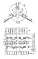
- such means comprise a radially movable bottom bar 38 (see Fig. 3) in each channel 24 supporting the entire row of pellets 10 therein, and a powered cylinder 40 (pneumatic, hydraulic, electric, or the like) operatively connected to the bottom bar 38 through a shaft 42.
- each channel 24 could have a stationary bottom member with a slit therein through which a first ejector bar could pass when the channel is in the first below-horizontal position, and through which a second ejector bar could pass when the channel is in the second below-horizontal position.
- Still another way of unloading pellets from the channels 24 in the drum 22 would be to provide for the pellets, e.g. by making the channel walls smooth enough, simply to slide out of the channels by gravity when the channels are in a below-horizontal, i.e., downwardly sloping, position, although positive pellets unloading from the channels by means of pusher mechanisms such as described above is preferred.
- the first and preferably also the second below-horizontal position for the channels 24 has associated therewith an incline or slide 44 or 46, respectively, which at its upper end is disposed to receive the pellets discharged from the respective channel 24 and sliding onto the associated incline 44 or 46.
- Each of the inclines 44 and 46 preferably is tilted downward about 30 degrees from the horizontal, and each preferably is longitudinally grooved to guide the sliding pellets 10.
- the system further includes means for positioning the first sintering boat 18 and the lower end of the first incline 44 relative to each other such that a row of pellets 10 having left a channel 24 and sliding down the first incline 44 will be smoothly deposited in the first sintering boat 18 where the next row of pellets 10 is to be stacked therein.
- such means are provided also for similarly positioning the second sintering boat 20 relative to the lower end of the second incline 46. It is desirable thatthe positioning means support the respective sintering boats 18 and 20 such that their bottoms lie in planes generally perpendicular to the respective inclines 44 and 46 associated therewith.
- a recommended order of stacking the pellet rows in each sintering boat 18 or 20 would be to place the first row of pellets 10 in the lower corner, the second row on top of the first row along the lower side of the boat, the third row on top of the second, lower side, of the boat, the third row on top of the second row along the lower side, and so forth, until the entire lower side, or end wall, of the boat has received a complete layer of pellets.
- the pellet row to be stacked next would be placed near the lower corner upon the completed first layer of pellets, and the process would be repeated until the sintering boat is fully loaded with pellets.
- the position of the next-to-be-stacked pellet row is predetermined or preselected based on the particular pellet stacking order chosen.
- a preferred relative positioning means for each sintering boat 18 or 20 includes a standard two-directional sliding table 47 or 48 comprising a boat support 49, which sliding table is adapted to be indexed by substantially one pellet length in one direction and by substantially one pellet diameter in another direction perpendicular to the first one.
- the inclines 44 and 46 are stationary in this case.
- the positioning means includes further a first positioning powered cylinder 50 for moving the boat support 49 in said one direction, and a second positioning powered cylinder 51 for moving the boat support 49 in the other direction.
- suitable relative positioning means may include: a movable bottom member for each incline and a corresponding standard one- directional sliding table for moving the sintering boat perpendicular to the direction of movement of the incline's bottom member; a robot arm for positioning each sintering boat; and the like.
- the sintering boat loading system further includes means for controlling the pellet receiving and inserting means, the drum rotating means, the relative positioning means, and the pellet pushing means.
- means for controlling the pellet receiving and inserting means, the drum rotating means, the relative positioning means, and the pellet pushing means Preferably such means includes a microprocessor 52, or the like, h for coordinating the operation of the system components previously discussed herein.
- the system could be operated to alternately load one row of pellets 10 at a time into each of the sintering boats 18 and 20 (in which case only 2 channels 24 would be needed), it is preferred that the microprocessor 52 be programmed so as to completely load one sintering boat before beginning to load the second sintering boat. As previously mentioned, this enables continuous pellet loading operation without shutting the system down for the purpose of changing sintering boats.
- the sintering-boat loading system illustrated and described herein operates under the control of the microprocessor 52 in the following manner.
- the drum 22 is positioned so as to have one of its channels 24 in the upper or pellet-receiving position.
- the pellets transferred from the turntable 14 onto the turntable 32 and thence onto the conveyor 34 are fed, in an upright position, into the appropriately positioned channel 24, preferably through a chute guiding the upright pellets single- file toward the aligned channel 24 of the drum, as seen from Fig. 1.
- suitable sensor means such as a switch (not shown), respond to supply a signal causing the motor 28 to advance the drum 22 through 120° in one direction, say, counterclockwise as viewed in Figs. 3 and 4, thereby to move the full channel 24 to its pellet discharging position associated with the incline 44 while, at the same time, moving the next channel 24 to the upright pellet receiving position associated with the conveyor 34.
- pellets 10 from the moving conveyor 34 are inserted into the channel 24 now in the receiving position, and the ejection bar 38 for the filled channel now in the discharging position is actuated to push the pellets from the associated channel and onto the incline 44, whereupon the row of pellets thus discharged will slide down the incline 44 and off it so as to be gently deposited in the sintering boat 18, namely, in the lower lefthand corner thereof (viewing Fig. 4) if this is the first row of pellets to be loaded into the boat 18.
- the positioning means 47, 50, 51 associated with the latter will operate to index the sliding table 47 and, thus, the boat 18 to the next pellet-row receiving position and the motor 28 at the same time will advance the drum 22 counterclockwise another 120°, whereupon the above- described pellet-inserting step (as regards the channel 24 now in the receiving position) and pellet-discharging step (as regards the preceding channel 24 now in the discharging position) are repeated, to be immediately followed by a further operation of the positioning means indexing the sintering boat 18 to its next pellet-row receiving position.
Description
- The present invention relates generally to handling nuclear fuel pellets and, more particularly, to a system for loading newly-made (green) nuclear fuel pellets into sintering boats from a pellet press.
- An operational step in the nuclear fuel fabrication process is the loading of green nuclear fuel pellets, which have been ejected from the pellet press, into sintering containers, "boats", in preparation for high-temperature firing of the pellets in a sintering furnace. This operation requires careful handling of the pellets, because the pellets at this time are fragile and susceptible to damage.
- It is known in the prior art to load nuclear fuel pellets into a sintering boat by a gravity discharge from the pellet press down a chute into the boat. This method has the disadvantage of allowing pellet to pellet impact and has considerable potential for pellet damage. In addition, random orientation of the pellets in each sintering boat reduces the loading density and therefore reduces the high-temperature firing production capacity.
- A mechanized boat loader also is known, in the prior art, which includes a pick and place mechanism with mechanical blades or jaws to pick up a single row of nuclear fuel pellets at a time and to transfer that row into the sintering boat. It further is known to utilize a boat loader with a vacuum transfer head which lowers onto an array of nuclear fuel pellets, applies a vacuum to lift the pellets, and transfers the array to load a complete layer of pellets into the sintering boat at one time. These two methods have the disadvantage of requiring frequent attention to maintain the pick and place mechanisms operational.
- U.S. Patent 4,332,120 discloses apparatus for loading nuclear fuel pellets, via gravity, into a container supported by a platform which lowers under increasing pellet weight thereon.
- U.S. Patent 3,027,020 discloses a rotating drum with longitudinally aligned circumferential channels to load rows of cans onto a conveyor.
- It is the principal object of the invention to provide a relatively maintenance-free sintering-boat loading system which achieves high loading density without nuclear fuel pellet damage.
- The invention accordingly resides in a system for loading nuclear-fuel pellets from a pellet press into sintering boats, comprising a rotatable drum supported for rotation about a substantially horizontal axis and including at least one channel for holding a row of said pellets, said channel extending axially of the drum from one end thereof, being open toward the outer periphery of the drum, and having an open end at said one end of the drum; means for rotating said drum so as to move the channel successively from a pellet-receiving position to a pellet-discharging position and again to said pellet-receiving position; pellet transferring means for receiving pellets from said pellet press and for inserting a row of the received pellets into said channel from the open end thereof when the channel is in the pellet-receiving position; means for supporting a sintering boat in a loading position; pellet-row transferring means for receiving the row of pellets from the channel after movement thereof to the pellet-discharging position, and for transferring the received row of pellets into the sintering boat supported in said loading position; and means operative after each transfer of a row of pellets into the sintering boat for changing the relative position between the sintering boat and the pellet-row transferring means in a manner causing successive rows of pellets transferred into the sintering boat to be stacked therein in a predetermined order.
- A preferred embodiment of the invention will now be described, by way of example only, with reference to the accompanying drawings, in which:
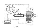
- Figure 1 is a schematic planar view of a nuclear fuel pellet sintering boat loading system embodying the invention;
- Figure 2 is an enlarged planar view of the rotating drum area shown in Figure 1;
- Figure 3 is an enlarged side elevational view of the rotating drum area shown in Figure 1; and
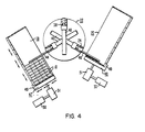
- Figure 4 is a schematic side elevational view of the rotating drum and sintering boat area shown in Figure 1.
- In the drawings, like reference characters designate like or corresponding parts. Newly made
nuclear fuel pellets 10 are formed by apellet press 12 which includes afirst turntable 14 and a firststationary wiper arm 16 to eject thepellets 10 therefrom. The system loads thepellets 10 into a first sinteringboat 18 and then loadsother pellets 10 from thepress 12 into a second sinteringboat 20 while the full first sinteringboat 18 is replaced with an empty boat. This permits continuous pellet loading operations. - The loading system includes a generally horizontally disposed
rotatable drum 22 which is provided with at least onechannel 24 which extends axially of the drum between theopposite ends 26 of the drum, is open toward the outer periphery of the drum, has an open end at one end 26a (Fig. 2) of thedrum 22, and is sized to hold a row ofpellets 10. Preferably, thedrum 22 has threesuch channels 24 spaced 120 degrees apart circumferentially about thedrum 22. - The loading system includes means for rotating the
drum 22 so as to move eachchannel 24 successively from a generally upward vertical position (pellet-receiving position) to a first generally below-horizontal position (pellet-discharging position) and around back to the upward vertical position. Preferably, the drum rotating means also includes means for counter-rotating thedrum 22 so as to move thechannel 24 from the upward vertical position the opposite direction sequentially to a second generally below-horizontal or pellet-discharging position, to the first below-horizontal position, and back to the upward vertical position. Preferably, the drum rotating and counter-rotating means include amotor 28 connected to thedrum 22 by ashaft 30. Preferably, the first below-horizontal position is substantially 120 degrees from the upward vertical position in one rotational direction of the drum, and the second below-horizontal position is substantially 120 degrees from the upward vertical position in the opposite rotational direction of the drum. - The loading system also includes means for receiving the
pellets 10 ejected from thepellet press 12, and for inserting the ejectedpellets 10 into the respective channel 24disposed at the time in the upward vertical position. Preferably, the pellet receiving and inserting means includes: apellet transfer turntable 32 which receivespellets 10 ejected from thepellet press 12, a stationarytransfer wiper arm 36 which guidespellets 10 off thetransfer turntable 32, and aconveyor 34 for receiving thepellets 10 guided off thetransfer turntable 32 by thetransfer wiper arm 36, for carrying thepellets 10 to thedrum 22, and for having the pellets in front be pushed into thealigned channel 24 by the pellets behind which are still on the movingconveyor 34. Thepellet press 12 will eject the standard right circular cylindrically shapedpellets 10 such that they will be standing up. Theconveyor 34 is so designed that any horizontally lying pellets, i.e., pellets which are not upright, will fall from the conveyor into a collector (not shown). This is accomplished by having the conveyor belt move over a camming surface (not shown) adapted to tilt the belt sufficiently to cause any toppled pellets to roll off. The preferred pellet receiving and inserting means described herein will maintain pellet orientation in that the pellets 10will be inserted into the alignedchannel 24 in an upright position. Other pellet receiving and inserting means include vibratory feeders, pick and place mechanisms and the like. - Preferably, means are additionally provided for pushing the row of
pellets 10 held in eachchannel 24 radially outward therefrom when thechannel 24 is disposed in either below-horizontal position. In the illustrated embodiment, such means comprise a radially movable bottom bar 38 (see Fig. 3) in eachchannel 24 supporting the entire row ofpellets 10 therein, and a powered cylinder 40 (pneumatic, hydraulic, electric, or the like) operatively connected to thebottom bar 38 through ashaft 42. Alternatively, and as not shown herein, eachchannel 24 could have a stationary bottom member with a slit therein through which a first ejector bar could pass when the channel is in the first below-horizontal position, and through which a second ejector bar could pass when the channel is in the second below-horizontal position. Still another way of unloading pellets from thechannels 24 in thedrum 22 would be to provide for the pellets, e.g. by making the channel walls smooth enough, simply to slide out of the channels by gravity when the channels are in a below-horizontal, i.e., downwardly sloping, position, although positive pellets unloading from the channels by means of pusher mechanisms such as described above is preferred. - The first and preferably also the second below-horizontal position for the
channels 24 has associated therewith an incline orslide respective channel 24 and sliding onto the associatedincline inclines sliding pellets 10. - The system further includes means for positioning the first sintering
boat 18 and the lower end of thefirst incline 44 relative to each other such that a row ofpellets 10 having left achannel 24 and sliding down thefirst incline 44 will be smoothly deposited in the first sinteringboat 18 where the next row ofpellets 10 is to be stacked therein. Preferably, such means are provided also for similarly positioning the second sinteringboat 20 relative to the lower end of thesecond incline 46. It is desirable thatthe positioning means support therespective sintering boats respective inclines boat pellets 10 in the lower corner, the second row on top of the first row along the lower side of the boat, the third row on top of the second, lower side, of the boat, the third row on top of the second row along the lower side, and so forth, until the entire lower side, or end wall, of the boat has received a complete layer of pellets. The pellet row to be stacked next would be placed near the lower corner upon the completed first layer of pellets, and the process would be repeated until the sintering boat is fully loaded with pellets. At any stage in the pellet loading operation, the position of the next-to-be-stacked pellet row is predetermined or preselected based on the particular pellet stacking order chosen. - As seen best from Fig. 4, a preferred relative positioning means for each sintering
boat boat support 49, which sliding table is adapted to be indexed by substantially one pellet length in one direction and by substantially one pellet diameter in another direction perpendicular to the first one. Theinclines cylinder 50 for moving theboat support 49 in said one direction, and a second positioning poweredcylinder 51 for moving theboat support 49 in the other direction. Other suitable relative positioning means may include: a movable bottom member for each incline and a corresponding standard one- directional sliding table for moving the sintering boat perpendicular to the direction of movement of the incline's bottom member; a robot arm for positioning each sintering boat; and the like. - The sintering boat loading system further includes means for controlling the pellet receiving and inserting means, the drum rotating means, the relative positioning means, and the pellet pushing means. Preferably such means includes a
microprocessor 52, or the like, h for coordinating the operation of the system components previously discussed herein. - Although the system could be operated to alternately load one row of
pellets 10 at a time into each of the sinteringboats 18 and 20 (in which case only 2channels 24 would be needed), it is preferred that themicroprocessor 52 be programmed so as to completely load one sintering boat before beginning to load the second sintering boat. As previously mentioned, this enables continuous pellet loading operation without shutting the system down for the purpose of changing sintering boats. - The sintering-boat loading system illustrated and described herein operates under the control of the
microprocessor 52 in the following manner. At the beginning of a loading cycle, thedrum 22 is positioned so as to have one of itschannels 24 in the upper or pellet-receiving position. Asgreen pellets 10 are supplied from thepellet press 12, and with theturntables conveyor 34 moving, as indicated by arrows in Fig. 1, the pellets transferred from theturntable 14 onto theturntable 32 and thence onto theconveyor 34 are fed, in an upright position, into the appropriately positionedchannel 24, preferably through a chute guiding the upright pellets single- file toward thealigned channel 24 of the drum, as seen from Fig. 1. When thechannel 24 in the pellet-receiving position is thus filled with pellets to its desired capacity, suitable sensor means, such as a switch (not shown), respond to supply a signal causing themotor 28 to advance thedrum 22 through 120° in one direction, say, counterclockwise as viewed in Figs. 3 and 4, thereby to move thefull channel 24 to its pellet discharging position associated with theincline 44 while, at the same time, moving thenext channel 24 to the upright pellet receiving position associated with theconveyor 34. Once thedrum 22 is thus positioned,pellets 10 from the movingconveyor 34 are inserted into thechannel 24 now in the receiving position, and theejection bar 38 for the filled channel now in the discharging position is actuated to push the pellets from the associated channel and onto theincline 44, whereupon the row of pellets thus discharged will slide down theincline 44 and off it so as to be gently deposited in thesintering boat 18, namely, in the lower lefthand corner thereof (viewing Fig. 4) if this is the first row of pellets to be loaded into theboat 18. With the first row of pellets thus placed in theboat 18, the positioning means 47, 50, 51 associated with the latter will operate to index the sliding table 47 and, thus, theboat 18 to the next pellet-row receiving position and themotor 28 at the same time will advance thedrum 22 counterclockwise another 120°, whereupon the above- described pellet-inserting step (as regards thechannel 24 now in the receiving position) and pellet-discharging step (as regards the precedingchannel 24 now in the discharging position) are repeated, to be immediately followed by a further operation of the positioning means indexing the sinteringboat 18 to its next pellet-row receiving position. This sequence of steps is reiterated until theboat 18 is fully loaded, whereupon the direction of 120° incremental drum rotation is reversed to initiate another loading cycle, one just as the one described above but applied to loading theother sintering boat 20. While this new loading cycle is progressing, the fully loadedboat 18 can be removed from the sliding table 47 and replaced with an empty sintering boat, to be loaded during the next loading cycle commencing upon the next reversal of drum rotation which will occur when loading of theboat 20 is completed. - It will be appreciated that different sizes of pellets or sintering boats would require appropriately sized interchangeable (or adjustable) system components.
Claims (16)
Applications Claiming Priority (2)
| Application Number | Priority Date | Filing Date | Title |
|---|---|---|---|
| US06/536,934 US4566835A (en) | 1983-09-28 | 1983-09-28 | Nuclear fuel pellet sintering boat loading system |
| US536934 | 1983-09-28 |
Publications (3)
| Publication Number | Publication Date |
|---|---|
| EP0140023A2 EP0140023A2 (en) | 1985-05-08 |
| EP0140023A3 EP0140023A3 (en) | 1986-03-12 |
| EP0140023B1 true EP0140023B1 (en) | 1988-11-17 |
Family
ID=24140521
Family Applications (1)
| Application Number | Title | Priority Date | Filing Date |
|---|---|---|---|
| EP84110361A Expired EP0140023B1 (en) | 1983-09-28 | 1984-08-31 | Nuclear fuel pellet sintering boat loading system |
Country Status (6)
| Country | Link |
|---|---|
| US (1) | US4566835A (en) |
| EP (1) | EP0140023B1 (en) |
| JP (1) | JPS6093394A (en) |
| KR (1) | KR910006876B1 (en) |
| DE (1) | DE3475239D1 (en) |
| ES (1) | ES8702690A1 (en) |
Families Citing this family (15)
| Publication number | Priority date | Publication date | Assignee | Title |
|---|---|---|---|---|
| US4672791A (en) * | 1984-12-05 | 1987-06-16 | Westinghouse Electric Corp. | Apparatus for applying an end plug to an end of a fuel rod tube |
| US4679377A (en) * | 1984-12-05 | 1987-07-14 | Westinghouse Electric Corp. | Apparatus for applying an end plug to an end of a fuel rod tube |
| US4748798A (en) * | 1985-05-10 | 1988-06-07 | Japan Nuclear Fuel Co., Ltd. | Apparatus for automatically loading nuclear fuel pellets |
| US4765453A (en) * | 1987-04-27 | 1988-08-23 | Westinghouse Electric Corp. | Pellet-press-to-sintering-boat nuclear fuel pellet loading system |
| US4807734A (en) * | 1987-07-24 | 1989-02-28 | Westinghouse Electric Corp. | Pellet-press-to-sintering-boat nuclear fuel pellet loading apparatus |
| JPH0634718Y2 (en) * | 1987-08-12 | 1994-09-07 | 三菱原子燃料株式会社 | Alignment device for nuclear fuel pellets |
| US4897858A (en) * | 1988-03-25 | 1990-01-30 | Westinghouse Electric Corp. | Nuclear fuel pellet collating system and method |
| US4842808A (en) * | 1988-03-25 | 1989-06-27 | Westinghouse Electric Corp. | Nuclear fuel pellet collating system |
| US5048666A (en) * | 1989-03-02 | 1991-09-17 | Westinghouse Electric Corp. | Nuclear fuel pellet transfer escalator |
| US5207976A (en) * | 1991-04-05 | 1993-05-04 | Westinghouse Electric Corp. | Pellet slide and inspection assembly in a nuclear fuel pellet surface defect inspection apparatus |
| US5489184A (en) * | 1994-09-13 | 1996-02-06 | Westinghouse Electric Corporation | Pellet loader |
| GB9625516D0 (en) * | 1996-12-09 | 1997-01-29 | British Nuclear Fuels Plc | Assembly of nuclear fuel elements |
| US6639961B2 (en) * | 2000-05-22 | 2003-10-28 | Framatome Cogema Fuel Co. | Nuclear fuel pellet loading method and machine for same |
| US20030164378A1 (en) * | 2002-02-01 | 2003-09-04 | Simson Anton K. | Beverage container unloading and dispensing apparatus |
| FR2892556B1 (en) * | 2005-10-24 | 2008-01-25 | Cogema | PLATFORM FILLING DEVICE WITH NUCLEAR FUEL PELLETS AND FILLING METHOD USING SUCH A DEVICE |
Family Cites Families (10)
| Publication number | Priority date | Publication date | Assignee | Title |
|---|---|---|---|---|
| US1580670A (en) * | 1922-02-10 | 1926-04-13 | Nagy Berthold | Delivery mechanism for bottle-cap-assembling machines |
| US3027020A (en) * | 1958-12-16 | 1962-03-27 | Lawrence B Mccoy | Pallet packer |
| ES303688A1 (en) * | 1964-08-24 | 1964-11-01 | Mas Ill Ramen | Computer mechanism to fill boxes of automatic telares (Machine-translation by Google Translate, not legally binding) |
| FR2061564B1 (en) * | 1969-07-09 | 1973-10-19 | Pechiney Ugine Kuhlmann | |
| US3789575A (en) * | 1971-10-04 | 1974-02-05 | Pennwalt Corp | Article packaging machine |
| JPS573291B2 (en) * | 1974-08-22 | 1982-01-20 | ||
| JPS5289657A (en) * | 1976-01-22 | 1977-07-27 | Shiono Koryo Kaisha | Process for manufacture of dihydrojasmone acid methyl and d 11jasmone ac1id methyl |
| JPS5420485U (en) * | 1977-07-13 | 1979-02-09 | ||
| US4332120A (en) * | 1980-03-05 | 1982-06-01 | Westinghouse Electric Corp. | Nuclear fuel pellet loading apparatus |
| US4468163A (en) * | 1982-03-25 | 1984-08-28 | General Electric Company | Tray loader method and apparatus for nuclear fuel pellets |
-
1983
- 1983-09-28 US US06/536,934 patent/US4566835A/en not_active Expired - Fee Related
-
1984
- 1984-08-31 EP EP84110361A patent/EP0140023B1/en not_active Expired
- 1984-08-31 DE DE8484110361T patent/DE3475239D1/en not_active Expired
- 1984-09-25 ES ES536224A patent/ES8702690A1/en not_active Expired
- 1984-09-27 JP JP59200714A patent/JPS6093394A/en active Granted
- 1984-09-28 KR KR1019840006026A patent/KR910006876B1/en active IP Right Grant
Also Published As
| Publication number | Publication date |
|---|---|
| ES536224A0 (en) | 1986-12-16 |
| DE3475239D1 (en) | 1988-12-22 |
| EP0140023A2 (en) | 1985-05-08 |
| ES8702690A1 (en) | 1986-12-16 |
| JPH0448693B2 (en) | 1992-08-07 |
| KR850002348A (en) | 1985-05-10 |
| JPS6093394A (en) | 1985-05-25 |
| EP0140023A3 (en) | 1986-03-12 |
| US4566835A (en) | 1986-01-28 |
| KR910006876B1 (en) | 1991-09-09 |
Similar Documents
| Publication | Publication Date | Title |
|---|---|---|
| EP0140023B1 (en) | Nuclear fuel pellet sintering boat loading system | |
| US5136826A (en) | Stacked container handling apparatus and process | |
| EP0339610B1 (en) | Method for shifting goods and apparatus therefor by inverting a container | |
| US4264253A (en) | Method and apparatus for forming a lumber stack and placing sticks between adjacent courses in the stack | |
| GB2158411A (en) | Apparatus for the automatic filling of stacked disk-shaped objects into packing containers open on one side | |
| US4955794A (en) | Apparatus for forming and conveying groups of flat stacked items | |
| US6398008B1 (en) | Aligning and conveying method of packaged article and apparatus thereof | |
| US6769856B2 (en) | Plant for unloading stacks of thermoformed objects from a receiving cage to a removing conveyer | |
| US6625953B1 (en) | Item handler for sorting and packing | |
| EP0385195B1 (en) | Nuclear fuel pellet transfer arrangement | |
| US4181212A (en) | Method and apparatus for feeding containers for rod-like articles | |
| GB2128970A (en) | Article storage unit and charging and/or discharging apparatus therefor | |
| US4071149A (en) | Apparatus for piling apertured articles in stacks for storage | |
| US4930289A (en) | Machine for packing tablets into tubes | |
| US5096371A (en) | Carton feeding apparatus | |
| US3283471A (en) | Automatic packing apparatus | |
| FR2724641A1 (en) | METHOD AND DEVICE FOR HANDLING LOADING PRODUCTS AND DISCHARGING COOKED PRODUCTS | |
| EP0365870B1 (en) | Signature handling apparatus | |
| EP0044684B1 (en) | Pellet workpiece container boat loading apparatus | |
| KR200286751Y1 (en) | Tray Feeder of Semiconductor Package Manufacturing Equipment | |
| JPH07172412A (en) | Apparatus for supplying and taking out work | |
| KR100217397B1 (en) | Conveying system of lithium battery | |
| JPS6221618A (en) | Method and device for automatically filling cheese | |
| CN219447495U (en) | Automatic full material switching tool | |
| US3509692A (en) | Device for transferring articles onto trays |
Legal Events
| Date | Code | Title | Description |
|---|---|---|---|
| PUAI | Public reference made under article 153(3) epc to a published international application that has entered the european phase |
Free format text: ORIGINAL CODE: 0009012 |
|
| AK | Designated contracting states |
Designated state(s): BE DE FR GB IT SE |
|
| PUAL | Search report despatched |
Free format text: ORIGINAL CODE: 0009013 |
|
| AK | Designated contracting states |
Kind code of ref document: A3 Designated state(s): BE DE FR GB IT SE |
|
| 17P | Request for examination filed |
Effective date: 19860820 |
|
| 17Q | First examination report despatched |
Effective date: 19871221 |
|
| ITF | It: translation for a ep patent filed |
Owner name: ING. ZINI MARANESI & C. S.R.L. |
|
| GRAA | (expected) grant |
Free format text: ORIGINAL CODE: 0009210 |
|
| AK | Designated contracting states |
Kind code of ref document: B1 Designated state(s): BE DE FR GB IT SE |
|
| REF | Corresponds to: |
Ref document number: 3475239 Country of ref document: DE Date of ref document: 19881222 |
|
| ET | Fr: translation filed | ||
| ITTA | It: last paid annual fee | ||
| PLBE | No opposition filed within time limit |
Free format text: ORIGINAL CODE: 0009261 |
|
| STAA | Information on the status of an ep patent application or granted ep patent |
Free format text: STATUS: NO OPPOSITION FILED WITHIN TIME LIMIT |
|
| 26N | No opposition filed | ||
| PGFP | Annual fee paid to national office [announced via postgrant information from national office to epo] |
Ref country code: FR Payment date: 19900622 Year of fee payment: 7 |
|
| PGFP | Annual fee paid to national office [announced via postgrant information from national office to epo] |
Ref country code: GB Payment date: 19900625 Year of fee payment: 7 Ref country code: SE Payment date: 19900625 Year of fee payment: 7 |
|
| PGFP | Annual fee paid to national office [announced via postgrant information from national office to epo] |
Ref country code: BE Payment date: 19900712 Year of fee payment: 7 |
|
| PGFP | Annual fee paid to national office [announced via postgrant information from national office to epo] |
Ref country code: DE Payment date: 19900929 Year of fee payment: 7 |
|
| PG25 | Lapsed in a contracting state [announced via postgrant information from national office to epo] |
Ref country code: GB Effective date: 19910831 Ref country code: BE Effective date: 19910831 |
|
| PG25 | Lapsed in a contracting state [announced via postgrant information from national office to epo] |
Ref country code: SE Effective date: 19910901 |
|
| BERE | Be: lapsed |
Owner name: WESTINGHOUSE ELECTRIC CORP. Effective date: 19910831 |
|
| GBPC | Gb: european patent ceased through non-payment of renewal fee | ||
| PG25 | Lapsed in a contracting state [announced via postgrant information from national office to epo] |
Ref country code: DE Effective date: 19920501 |
|
| EUG | Se: european patent has lapsed |
Ref document number: 84110361.7 Effective date: 19920408 |
|
| PG25 | Lapsed in a contracting state [announced via postgrant information from national office to epo] |
Ref country code: FR Effective date: 19950731 |
|
| REG | Reference to a national code |
Ref country code: FR Ref legal event code: ST |
|
| PG25 | Lapsed in a contracting state [announced via postgrant information from national office to epo] |
Ref country code: FR Effective date: 19910831 |