EP0365870B1 - Signature handling apparatus - Google Patents
Signature handling apparatus Download PDFInfo
- Publication number
- EP0365870B1 EP0365870B1 EP19890118226 EP89118226A EP0365870B1 EP 0365870 B1 EP0365870 B1 EP 0365870B1 EP 19890118226 EP19890118226 EP 19890118226 EP 89118226 A EP89118226 A EP 89118226A EP 0365870 B1 EP0365870 B1 EP 0365870B1
- Authority
- EP
- European Patent Office
- Prior art keywords
- signatures
- container
- stack
- cells
- containers
- Prior art date
- Legal status (The legal status is an assumption and is not a legal conclusion. Google has not performed a legal analysis and makes no representation as to the accuracy of the status listed.)
- Expired - Lifetime
Links
Images

Classifications
-
- B—PERFORMING OPERATIONS; TRANSPORTING
- B65—CONVEYING; PACKING; STORING; HANDLING THIN OR FILAMENTARY MATERIAL
- B65H—HANDLING THIN OR FILAMENTARY MATERIAL, e.g. SHEETS, WEBS, CABLES
- B65H1/00—Supports or magazines for piles from which articles are to be separated
- B65H1/28—Supports or magazines for piles from which articles are to be separated compartmented to receive piles side-by-side
-
- B—PERFORMING OPERATIONS; TRANSPORTING
- B62—LAND VEHICLES FOR TRAVELLING OTHERWISE THAN ON RAILS
- B62B—HAND-PROPELLED VEHICLES, e.g. HAND CARTS OR PERAMBULATORS; SLEDGES
- B62B3/00—Hand carts having more than one axis carrying transport wheels; Steering devices therefor; Equipment therefor
- B62B3/008—Hand carts having more than one axis carrying transport wheels; Steering devices therefor; Equipment therefor having more than two axes
-
- B—PERFORMING OPERATIONS; TRANSPORTING
- B65—CONVEYING; PACKING; STORING; HANDLING THIN OR FILAMENTARY MATERIAL
- B65H—HANDLING THIN OR FILAMENTARY MATERIAL, e.g. SHEETS, WEBS, CABLES
- B65H31/00—Pile receivers
- B65H31/30—Arrangements for removing completed piles
- B65H31/3036—Arrangements for removing completed piles by gripping the pile
- B65H31/3045—Arrangements for removing completed piles by gripping the pile on the outermost articles of the pile for clamping the pile
-
- B—PERFORMING OPERATIONS; TRANSPORTING
- B65—CONVEYING; PACKING; STORING; HANDLING THIN OR FILAMENTARY MATERIAL
- B65H—HANDLING THIN OR FILAMENTARY MATERIAL, e.g. SHEETS, WEBS, CABLES
- B65H33/00—Forming counted batches in delivery pile or stream of articles
- B65H33/16—Forming counted batches in delivery pile or stream of articles by depositing articles in batches on moving supports
-
- B—PERFORMING OPERATIONS; TRANSPORTING
- B62—LAND VEHICLES FOR TRAVELLING OTHERWISE THAN ON RAILS
- B62B—HAND-PROPELLED VEHICLES, e.g. HAND CARTS OR PERAMBULATORS; SLEDGES
- B62B2202/00—Indexing codes relating to type or characteristics of transported articles
- B62B2202/64—Documents, files or paper sheets
-
- B—PERFORMING OPERATIONS; TRANSPORTING
- B65—CONVEYING; PACKING; STORING; HANDLING THIN OR FILAMENTARY MATERIAL
- B65H—HANDLING THIN OR FILAMENTARY MATERIAL, e.g. SHEETS, WEBS, CABLES
- B65H2301/00—Handling processes for sheets or webs
- B65H2301/40—Type of handling process
- B65H2301/42—Piling, depiling, handling piles
- B65H2301/422—Handling piles, sets or stacks of articles
- B65H2301/4224—Gripping piles, sets or stacks of articles
- B65H2301/42242—Gripping piles, sets or stacks of articles by acting on the outermost articles of the pile for clamping the pile
-
- B—PERFORMING OPERATIONS; TRANSPORTING
- B65—CONVEYING; PACKING; STORING; HANDLING THIN OR FILAMENTARY MATERIAL
- B65H—HANDLING THIN OR FILAMENTARY MATERIAL, e.g. SHEETS, WEBS, CABLES
- B65H2301/00—Handling processes for sheets or webs
- B65H2301/40—Type of handling process
- B65H2301/42—Piling, depiling, handling piles
- B65H2301/422—Handling piles, sets or stacks of articles
- B65H2301/4225—Handling piles, sets or stacks of articles in or on special supports
- B65H2301/42254—Boxes; Cassettes; Containers
-
- B—PERFORMING OPERATIONS; TRANSPORTING
- B65—CONVEYING; PACKING; STORING; HANDLING THIN OR FILAMENTARY MATERIAL
- B65H—HANDLING THIN OR FILAMENTARY MATERIAL, e.g. SHEETS, WEBS, CABLES
- B65H2301/00—Handling processes for sheets or webs
- B65H2301/40—Type of handling process
- B65H2301/42—Piling, depiling, handling piles
- B65H2301/422—Handling piles, sets or stacks of articles
- B65H2301/4226—Delivering, advancing piles
- B65H2301/42264—Delivering, advancing piles by moving the surface supporting the lowermost article of the pile, e.g. conveyor, carriage
-
- B—PERFORMING OPERATIONS; TRANSPORTING
- B65—CONVEYING; PACKING; STORING; HANDLING THIN OR FILAMENTARY MATERIAL
- B65H—HANDLING THIN OR FILAMENTARY MATERIAL, e.g. SHEETS, WEBS, CABLES
- B65H2402/00—Constructional details of the handling apparatus
- B65H2402/30—Supports; Subassemblies; Mountings thereof
- B65H2402/35—Supports; Subassemblies; Mountings thereof rotating around an axis
- B65H2402/351—Turntables
-
- B—PERFORMING OPERATIONS; TRANSPORTING
- B65—CONVEYING; PACKING; STORING; HANDLING THIN OR FILAMENTARY MATERIAL
- B65H—HANDLING THIN OR FILAMENTARY MATERIAL, e.g. SHEETS, WEBS, CABLES
- B65H2405/00—Parts for holding the handled material
- B65H2405/30—Other features of supports for sheets
- B65H2405/33—Compartmented support
- B65H2405/331—Juxtaposed compartments
-
- B—PERFORMING OPERATIONS; TRANSPORTING
- B65—CONVEYING; PACKING; STORING; HANDLING THIN OR FILAMENTARY MATERIAL
- B65H—HANDLING THIN OR FILAMENTARY MATERIAL, e.g. SHEETS, WEBS, CABLES
- B65H2405/00—Parts for holding the handled material
- B65H2405/30—Other features of supports for sheets
- B65H2405/36—Multiple support
- B65H2405/361—Movable from storage of support, e.g. stack of empty support
Definitions
- the present invention relates to an apparatus for use in building and handling stacks of signatures according to claim 1.
- an assembly for storing semi-finished products which are ejected from a printing machine and for transporting the same to a further processing machine including at least one transport magazine incorporating a clamping device for receiving and clamping the semi-finished products.
- that assembly comprises a device for filling the magazines, provided with a pressing device, and a magazine unloading device.
- the device for filling the magazines consists of a stacker member and a magazine support member to which the pressing device is assigned.
- the stack formed in the stacker member is movable into the magazine support member by means of a transport device.
- the present invention resides in an improved system for handling and storing printed products such as inserts and signatures, hereinafter referred to as signatures, prior to their being collated to form a newspaper, magazine, book, etc.
- the present invention resides in an improved handling system wherein stacks of signatures are placed in a container and handled and stored as a group.
- group for purposes of the present application, it is meant two or more stacks of signatures.
- the present invention resides in an improved system for building and handling stacks of signatures which comprises the features defined in claim 1.
- the container with the signatures therein may be stored.
- the container maintains the signatures in a uniform stack and protects the signatures from damage.
- the container is moved to a collator where the stacks are removed from the container and the signatures are collated with other printed products to form a newspaper, magazine, book, etc.
- the containers comprise an elongated, longitudinally extending, axial central support and longitudinally extending wall means emanating from said support in a pin-wheel fashion defining an array of longitudinally extending, generally rectangular, open-top, cells positioned radially around the support. This permits the containers to be rotatably indexed at the stacker for sequentially loading the container cells, and to be rotatably indexed at the collator for sequentially unloading the container cells.
- the signature handling system 12 of the present invention comprises a conveyor assembly 14 made up of a plurality of sections to be described. Only a part of the conveyor assembly is shown in Fig. 1.
- Each container is an upright member having a rectangular cross-section and a central, longitudinally extending, square, tubular central support 18.
- Four L-shaped dividers 20 extend outwardly from the support 18 somewhat in the shape of a swastika arranged to form four separate cubical cells 22 arranged radially around the central support 18.
- each L-shaped divider 20 comprises an inner flat wall surface or leg 24 which is common to adjacent cells. Attached to the free edge of each leg 24, at right angles to the leg, is an outer flat wall 26. Each wall 26 defines an outer surface portion of the adjacent cells 22. Each cell 22 is enclosed on three sides and substantially open on a fourth side 28, except for stack retaining flanges 30 and 32 located along opposite longitudinally extending edges of each of the open sides and formed by adjacent parts of adjacent outer walls 26.
- a main run of the conveyor assembly comprises sections 34a and 34b which are positioned on opposite sides of the front of a stacker 36.
- the stacker 36 is adapted to load stacks of signatures into the individual cells 22 of the container 16. These signatures, identified with the numeral 38, are transferred to the stacker from a printing press (not shown) by means of a conveyor 39.
- the conveyor assembly 14 includes an indexing mechanism 40 in the form of a rotatable square platform onto which the advancing containers are positioned by the conveyor section 34a, the conveyor sections 34a and 34b embracing opposite sides of the indexing mechanism or platform.
- the platform 40 includes a mechanism which enters the central tubular support 18. The mechanism rotates the container relative to the stacker so that an empty container cell 22 is aligned with the front of the stacker. When that cell has been loaded with a predetermined number of signatures, the platform 40 is then shifted and rotatably indexed again so that the next empty cell is aligned with the front of the stacker to receive a stack of signatures. When all of the cells are filled, the container 16 is advanced off of the platform 40 and moved by the conveyor 34b to a storage location (not shown) or to an unloading station 43, as shown in Fig. 3, to be described.
- the stacker 36 is provided with a plurality of platforms 41 which are mounted on an endless chain mechanism 42 trained around spaced apart sprockets 44 and 46.
- the chain mechanism 42 is positioned along the inclined front face 48 of the stacker 36 so that successive platforms intercept signatures from the signature conveyor 39. Movement of the chain 42 is timed to move the platforms 41 downwardly along the face 48 of the stacker at the same rate at which a stack 50 of signatures on a platform grows. This keeps the top of a growing stack of signatures at an intercept position registered with conveyor 39.
- platforms 41 are shown attached to chain 42, there are, in reality, several more, for instance three additional platforms, the exact number being a function of stack height desired, size of equipment and speed of operation of the system components.
- the spacing between platforms is that necessary to allow one stack to be built before interception of the flow of signatures by a following platform and start of a new stack.
- the chain mechanism 42 is comprised of a pair of co-extensive chains, and alternate platforms 41 are mounted on one chain or the other.
- the chains are independently movable. As one platform 41 is being loaded, the chain for the next platform is advanced so that this platform is poised for interception of the stream of signatures 38 when loading of the preceding platform is completed. Rapid activation of an intercepting platform is achieved by pivotally mounting the platform on the respective chains.
- the platforms in the poised position are held in a raised spring-loaded mode by a latch which is adapted to release the platforms to the intercepting mode when loading of the preceding platform is completed. In this way, the continuous movement of the signatures can be maintained without interruption.
- the chain mechanism 42 and associated platforms are substantially co-extensive with the inclined face 48 of the stacker 22.
- a second chain mechanism 52 is provided below the mechanism 42 which is substantially co-extensive with the lower vertical face 54 of the stacker.
- This chain mechanism is trained around a lower sprocket 56 and an upper sprocket (not shown) which is coaxial with sprocket 46.
- Attached to the chain mechanism 52 is a fork 58 which is adapted to be moved in and out from the face of the stacker in the direction of arrows 60, actuated by actuator 62, and which is adapted to be moved up and down in the direction of arrows 64 by movement of the chain mechanism 52.
- the chain mechanism 52 is driven by reversible motors 66 and 66a, coupled to the chain mechanism through clutch and brake mechanisms 68 and 68a. These are arranged to drive the chain at different speeds.
- the fork 58 is initially positioned at its uppermost point of travel which is adapted to be slightly above the lowermost point of travel of the platforms 41.
- the platforms 41 are configured to mesh with and pass by the fork 58 in their downward travel so that a stack of signatures on a platform 41 is transferred from the platform 41 to the fork 58.
- the fork 58 on receipt of a stack of signatures is then lowered to its lowermost position, actuated by motors 66 and 66a.
- the stack 50 is reposed on an incline against upper face 48 when transferred to fork 58.
- the stack In downward movement of the fork, the stack is deflected into a vertical repose by means of a deflecting surface at the point of juncture between the inclined face 48 and the vertical face 54 of the stacker.
- the fork 58 is in its uppermost position shown in Fig. 2 in dashed lines when a cell open side 28 is indexed so as to be adjacent the vertical face 54 of the stacker.
- the motors 66 and 66a are suitably timed to coincide with indexing of the container cells to lower a stack of signatures into an empty cell subsequent to indexing. This position of a stack of signatures is shown in full lines in Fig. 2.
- the fork 58 is withdrawn by means of actuator 62 so that the stack rests upon the bottom of the cell, and the container is then indexed for a repeat of the above procedure with the next cell.
- motors 66 and 66a On withdrawal of the fork 58, it is quickly raised by motors 66 and 66a to its uppermost position to receive the next stack of signatures.
- an advancing container 16 is received onto a platform 74 which is at that time in a horizontal position but which, in Fig. 3, is shown in a vertical, unloading position.
- the container 16 is attached to the platform, and the platform is then pivoted about edge 76 so that the container cells extend horizontally.
- the platform 74 is shown in the after-pivoted, vertical position.
- the platform 74 is a cubical element having open sides 78 and 80, a floor 82, a top 84, and closed sides 86 and 88.
- an advancing container 16 is admitted to the platform 74 through open side 80, and is positioned in the center of the platform.
- the container central support 18 is engaged by pins (not shown) seated in the floor 82 and top 84 adapted to hold the container in its centered position during pivoting of the platform and to rotate the container during unloading.
- These pins are square members adapted to seat within the square configuration of the central support 18 and are provided with a suitable actuating means (also not shown) to effect such seating and to index or rotate the containers.
- one of the container cells is initially indexed to register with a hopper/loader 90 for a collator (not shown) or other desired processing apparatus.
- the top 84 of the platform 74 is suitably slotted at 92 so that signatures can be ejected from the registered container cell onto the hopper loader. Ejection is accomplished by means of a pusher element 94 reversibly movable along side 88 in the directions shown by arrows 96.
- the pusher element has tines 98 which are adapted to pass through slots 100 in the bottom of the container cells and engage the bottom of a signature stack 50. Movement of the pusher element in the direction of the hopper/loader along the cell open side 28 causes the stack of signatures to move onto the hopper/loader.
- the container 16 When a container cell is empty, the container 16 is then indexed about its longitudinal central axis 18 so that the next container cell can be unloaded. This is repeated until all of the container cells are empty.
- the platform 74 then pivots about its edge 76 so that it again extends horizontally.
- the empty container 16 at this point is then ejected from the platform through open side 78 onto conveyor section 34d for return to the stacker 36 or other location and another full container is received onto the platform for repeat of the above cycle.
- FIG. 3 An alternative to the unloading sequence of Fig. 3 is to unload the containers manually.
- the containers can be transported by means of the conveyor assembly onto a rotatable table which is provided with an indexing means to automatically index the containers for manual removal of signatures from the container cells by an individual positioned at a fixed spot at the unloading station.
- the container On emptying one cell, the container is then indexed by the indexing means actuated by the operator for manual removal of signatures from the next cell, which cycle is repeated until the container is emptied.
- the container can be emptied without the operator having to shift his position.
- an advantage of the present invention lay in improved handling and processing of stacks of signatures or other flat products.
- the stacks are protected from damage and are stably and securely transported from one location to another.
- the stacks of signatures can be more accurately registered with the loading or unloading means than if the stacks were transported in individual containers as in the Bain Patent 4,462,735.
- Accurate handling of a stack of signatures requires accurate registration with the handling means. Any displacement of an individual container from its position on a conveyor in the transfer step can result in misalignment of the container with the handling means and possible malfunction. The likelihood of such malfunction is minimized in the present invention by grouping the signature stacks in a plurality of connected container cells. By protecting the signatures from damage, the likelihood of misfeed at a processing location is also minimized.
Landscapes
- Engineering & Computer Science (AREA)
- Mechanical Engineering (AREA)
- Chemical & Material Sciences (AREA)
- Combustion & Propulsion (AREA)
- Transportation (AREA)
- Forming Counted Batches (AREA)
- Collation Of Sheets And Webs (AREA)
- Specific Conveyance Elements (AREA)
Description
- The present invention relates to an apparatus for use in building and handling stacks of signatures according to claim 1.
- It is common practice to print portions of a newspaper, called inserts, and to store these portions prior to collating the newspaper for delivery. It is equally common practice to print portions of a book, magazine, etc. called signatures, and to store these portions prior to collating. US-Prior Patent No. 4,538,511, to James C. Wise, assigned to the assignee of the present application, entitled "Signature Handling Apparatus", discloses a system for stacking signatures. A transfer vehicle is movable to the stacker to clamp onto a stack and transfer that stack to an adjacent tying station where the stack is tied to form a log or bundle. The transfer vehicle maintains positive engagement with the stack as it moves the stack from the tying station to a stack-delivery station.
- Related embodiments of the system of the '511 patent are disclosed in prior US-Patent No. 4,541,763 (Chandhoke et al.), entitled "Apparatus for Forming a Stack of Signatures". This patent is also assigned to the assignee of the present application.
- In prior US-Patent No. 4,498,381, to Frank H. Convey, Jr., assigned to the assignee of the present application, there is disclosed a further embodiment of the system of the '511 patent in which there is provided a clamping mechanism capable of bringing end boards to the stacker, and depositing the end boards on the stack as the clamping mechanism engages a stack. The clamping mechanism also has independently movable clamp members that can move to different coextants in applying pressure to different portions of a stack of signatures during the clamping process.
- Also in the prior art is US-Patent No. 4,462,735 to Bain et al., which discloses a system for handling newspapers whereby a reserve supply of newspapers can be maintained capable of compensating for unintentional shutdown of a printing press. In the '735 patent, an endless conveyor has carriers adapted to travel about the pathway of the conveyor and to removably support newspaper containers. A pair of spaced transfer conveyors operatively associated with the endless conveyor are adapted to sequentially receive and then return the containers to the endless conveyor. On one transfer conveyor the containers are positioned by an indexing member at a location for receiving a stack of newspapers, and on the other transfer conveyor the containers are indexed to a position where the newspapers are unloaded for further processing.
- In prior art publication DE-A-2 719 991 there is disclosed an assembly for storing semi-finished products which are ejected from a printing machine and for transporting the same to a further processing machine, including at least one transport magazine incorporating a clamping device for receiving and clamping the semi-finished products. Further, that assembly comprises a device for filling the magazines, provided with a pressing device, and a magazine unloading device. The device for filling the magazines consists of a stacker member and a magazine support member to which the pressing device is assigned. The stack formed in the stacker member is movable into the magazine support member by means of a transport device.
- The prior art US-A-3 874 522 discloses a similar system, but for building and handling arrays and not stack of signatures.
- The present invention resides in an improved system for handling and storing printed products such as inserts and signatures, hereinafter referred to as signatures, prior to their being collated to form a newspaper, magazine, book, etc.
- More specifically, the present invention resides in an improved handling system wherein stacks of signatures are placed in a container and handled and stored as a group. By the term "group", for purposes of the present application, it is meant two or more stacks of signatures. By grouping the stacks of signatures in a container, the risk of stacks toppling over or falling off of a pallet is reduced. Also, the risk of damage to signatures is reduced thereby making the collating operation more efficient and less likely to be subject to misfeed problems due to signature damage. Still further, grouping the stacks of signatures facilitates movement of the signatures and overall processing in the printing and collating plant.
- The present invention resides in an improved system for building and handling stacks of signatures which comprises the features defined in claim 1.
- After the cells of the container are filled, the container with the signatures therein may be stored. The container maintains the signatures in a uniform stack and protects the signatures from damage. At the appropriate time, the container is moved to a collator where the stacks are removed from the container and the signatures are collated with other printed products to form a newspaper, magazine, book, etc.
- In a preferred embodiment of the present invention, the containers comprise an elongated, longitudinally extending, axial central support and longitudinally extending wall means emanating from said support in a pin-wheel fashion defining an array of longitudinally extending, generally rectangular, open-top, cells positioned radially around the support. This permits the containers to be rotatably indexed at the stacker for sequentially loading the container cells, and to be rotatably indexed at the collator for sequentially unloading the container cells.
- The invention and advantages thereof will become more apparent upon consideration of the following specification, with reference to the accompanying drawings, in which:
- Figure 1 is a perspective view of a signature handling system in accordance with the concepts of the present invention;
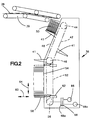
- Figure 2 is a side elevation view of a stacker of the system of Fig. 1, showing stacking of signatures conveyed from a printing press; and
- Figure 3 is a front elevation view of a container unloading mechanism in the system of Fig. 1.
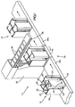
- Referring to Fig. 1, the
signature handling system 12 of the present invention comprises aconveyor assembly 14 made up of a plurality of sections to be described. Only a part of the conveyor assembly is shown in Fig. 1. - Positioned on the conveyor assembly are a plurality of
containers 16 in various stages in the handling system. Each container is an upright member having a rectangular cross-section and a central, longitudinally extending, square, tubularcentral support 18. Four L-shaped dividers 20 extend outwardly from thesupport 18 somewhat in the shape of a swastika arranged to form fourseparate cubical cells 22 arranged radially around thecentral support 18. - As shown, each L-
shaped divider 20 comprises an inner flat wall surface orleg 24 which is common to adjacent cells. Attached to the free edge of eachleg 24, at right angles to the leg, is an outerflat wall 26. Eachwall 26 defines an outer surface portion of theadjacent cells 22. Eachcell 22 is enclosed on three sides and substantially open on afourth side 28, except forstack retaining flanges outer walls 26. - A main run of the conveyor assembly comprises
sections stacker 36. Thestacker 36 is adapted to load stacks of signatures into theindividual cells 22 of thecontainer 16. These signatures, identified with thenumeral 38, are transferred to the stacker from a printing press (not shown) by means of aconveyor 39. - At the stacker, the
conveyor assembly 14 includes anindexing mechanism 40 in the form of a rotatable square platform onto which the advancing containers are positioned by theconveyor section 34a, theconveyor sections platform 40 includes a mechanism which enters the centraltubular support 18. The mechanism rotates the container relative to the stacker so that anempty container cell 22 is aligned with the front of the stacker. When that cell has been loaded with a predetermined number of signatures, theplatform 40 is then shifted and rotatably indexed again so that the next empty cell is aligned with the front of the stacker to receive a stack of signatures. When all of the cells are filled, thecontainer 16 is advanced off of theplatform 40 and moved by theconveyor 34b to a storage location (not shown) or to anunloading station 43, as shown in Fig. 3, to be described. - At this point, an empty container can then be positioned on the
platform 40 and the above cycle repeats itself. - Details of the
stacker 36 are schematically shown in Fig. 2. The stacker is provided with a plurality ofplatforms 41 which are mounted on anendless chain mechanism 42 trained around spaced apartsprockets chain mechanism 42 is positioned along the inclinedfront face 48 of thestacker 36 so that successive platforms intercept signatures from thesignature conveyor 39. Movement of thechain 42 is timed to move theplatforms 41 downwardly along theface 48 of the stacker at the same rate at which astack 50 of signatures on a platform grows. This keeps the top of a growing stack of signatures at an intercept position registered withconveyor 39. - Whereas only three
platforms 41 are shown attached tochain 42, there are, in reality, several more, for instance three additional platforms, the exact number being a function of stack height desired, size of equipment and speed of operation of the system components. The spacing between platforms is that necessary to allow one stack to be built before interception of the flow of signatures by a following platform and start of a new stack. - Details of the stacking mechanism above-described are disclosed in prior US-Patent No. 4,401,021 to Noll, Jr., assigned to the assignee of the present application, and in prior US-Patent No. 4,718,807 to Baxter, also assigned to the assignee of the present application. The disclosures of US-Patents Nos. 4,401,021 and 4,718,807 are incorporated by reference herein. As disclosed in US-Patent 4,401,021, a counter is arranged to count the number of signatures on a platform. Interception of the flow of signatures from
conveyor 39 by a successive platform is initiated when a predetermined desired number of signatures are positioned on the platform being loaded. - The
chain mechanism 42 is comprised of a pair of co-extensive chains, andalternate platforms 41 are mounted on one chain or the other. The chains are independently movable. As oneplatform 41 is being loaded, the chain for the next platform is advanced so that this platform is poised for interception of the stream ofsignatures 38 when loading of the preceding platform is completed. Rapid activation of an intercepting platform is achieved by pivotally mounting the platform on the respective chains. The platforms in the poised position are held in a raised spring-loaded mode by a latch which is adapted to release the platforms to the intercepting mode when loading of the preceding platform is completed. In this way, the continuous movement of the signatures can be maintained without interruption. - As shown in Fig. 2, the
chain mechanism 42 and associated platforms are substantially co-extensive with theinclined face 48 of thestacker 22. Asecond chain mechanism 52 is provided below themechanism 42 which is substantially co-extensive with the lowervertical face 54 of the stacker. This chain mechanism is trained around alower sprocket 56 and an upper sprocket (not shown) which is coaxial withsprocket 46. - Attached to the
chain mechanism 52 is afork 58 which is adapted to be moved in and out from the face of the stacker in the direction ofarrows 60, actuated byactuator 62, and which is adapted to be moved up and down in the direction ofarrows 64 by movement of thechain mechanism 52. Thechain mechanism 52 is driven byreversible motors brake mechanisms - In operation, the
fork 58 is initially positioned at its uppermost point of travel which is adapted to be slightly above the lowermost point of travel of theplatforms 41. Theplatforms 41 are configured to mesh with and pass by thefork 58 in their downward travel so that a stack of signatures on aplatform 41 is transferred from theplatform 41 to thefork 58. Thefork 58 on receipt of a stack of signatures is then lowered to its lowermost position, actuated bymotors stack 50 is reposed on an incline againstupper face 48 when transferred to fork 58. In downward movement of the fork, the stack is deflected into a vertical repose by means of a deflecting surface at the point of juncture between theinclined face 48 and thevertical face 54 of the stacker. - Referring to Figs. 1 and 2, the
fork 58 is in its uppermost position shown in Fig. 2 in dashed lines when a cellopen side 28 is indexed so as to be adjacent thevertical face 54 of the stacker. Themotors fork 58 is withdrawn by means ofactuator 62 so that the stack rests upon the bottom of the cell, and the container is then indexed for a repeat of the above procedure with the next cell. On withdrawal of thefork 58, it is quickly raised bymotors - Above, it was indicated that the filled
containers 16 following loading were transferred to an unloadingstation 43, shown in Fig. 3, or alternatively to a storage area (not shown). Normally, a container following loading will go to storage. When a book, magazine, or newspaper is ready for collating, the filled container will then be pulled from storage and transferred to the unloadingstation 43. Referring to Fig. 3, this is accomplished by means ofconveyor section 34c. In Fig. 3,conveyor section 34d transports an emptiedcontainer 16 back toloader 36 for reuse. - At the unloading
station 43, an advancingcontainer 16 is received onto aplatform 74 which is at that time in a horizontal position but which, in Fig. 3, is shown in a vertical, unloading position. For unloading, thecontainer 16 is attached to the platform, and the platform is then pivoted aboutedge 76 so that the container cells extend horizontally. In Fig. 3, theplatform 74 is shown in the after-pivoted, vertical position. - The
platform 74 is a cubical element havingopen sides floor 82, a top 84, and closedsides container 16 is admitted to theplatform 74 throughopen side 80, and is positioned in the center of the platform. At this point, the containercentral support 18 is engaged by pins (not shown) seated in thefloor 82 and top 84 adapted to hold the container in its centered position during pivoting of the platform and to rotate the container during unloading. These pins are square members adapted to seat within the square configuration of thecentral support 18 and are provided with a suitable actuating means (also not shown) to effect such seating and to index or rotate the containers. - On rotation of a container, one of the container cells is initially indexed to register with a hopper/
loader 90 for a collator (not shown) or other desired processing apparatus. The top 84 of theplatform 74 is suitably slotted at 92 so that signatures can be ejected from the registered container cell onto the hopper loader. Ejection is accomplished by means of apusher element 94 reversibly movable alongside 88 in the directions shown byarrows 96. The pusher element hastines 98 which are adapted to pass throughslots 100 in the bottom of the container cells and engage the bottom of asignature stack 50. Movement of the pusher element in the direction of the hopper/loader along the cellopen side 28 causes the stack of signatures to move onto the hopper/loader. - When a container cell is empty, the
container 16 is then indexed about its longitudinalcentral axis 18 so that the next container cell can be unloaded. This is repeated until all of the container cells are empty. Theplatform 74 then pivots about itsedge 76 so that it again extends horizontally. Theempty container 16 at this point is then ejected from the platform throughopen side 78 ontoconveyor section 34d for return to thestacker 36 or other location and another full container is received onto the platform for repeat of the above cycle. - An alternative to the unloading sequence of Fig. 3 is to unload the containers manually. Here also, the containers can be transported by means of the conveyor assembly onto a rotatable table which is provided with an indexing means to automatically index the containers for manual removal of signatures from the container cells by an individual positioned at a fixed spot at the unloading station. On emptying one cell, the container is then indexed by the indexing means actuated by the operator for manual removal of signatures from the next cell, which cycle is repeated until the container is emptied. The container can be emptied without the operator having to shift his position.
- Above, it was indicated that an advantage of the present invention lay in improved handling and processing of stacks of signatures or other flat products. By grouping the stacks of signatures in a container having a plurality of cells, the stacks are protected from damage and are stably and securely transported from one location to another. At a loading or unloading station, the stacks of signatures can be more accurately registered with the loading or unloading means than if the stacks were transported in individual containers as in the Bain Patent 4,462,735. Accurate handling of a stack of signatures requires accurate registration with the handling means. Any displacement of an individual container from its position on a conveyor in the transfer step can result in misalignment of the container with the handling means and possible malfunction. The likelihood of such malfunction is minimized in the present invention by grouping the signature stacks in a plurality of connected container cells. By protecting the signatures from damage, the likelihood of misfeed at a processing location is also minimized.
Claims (4)
- An apparatus for use in building and handling stacks of signatures, said apparatus comprising:
a stacker (36) to receive signatures (38) and form a stack of signatures,
said stacker comprising loading means (41, 58) for loading stacks of signatures into a plurality of containers (16),
conveyor means (34a and 34b) for sequentially transferring empty containers to said stacker and transferring containers holding stacks of signatures from said stacker,
said apparatus being characterized by each container (16) having wall means (20, 24) defining a plurality of cells (22), each of said cells having a substantially rectangular cross section with an open upper end portion and an opening extending along a side wall of the container from the open upper end portion to a lower end portion of the container, said loading means (41, 58) loading each of said cells (22) by lowering a stack of signatures into each of said cells (22) in turn with a portion of said loading means (58) extending through the opening in the side wall of the container into a cell (22) as a stack of signatures is lowered into the cell, and indexing means (40) for rotating each of said containers (16) in turn about a vertical axis to move a cell (22) with a stack of signatures therein away from said loading means (41, 58) and to simultaneously move an empty cell (22) of the container (16) toward said loading means (41, 58). - An apparatus as set forth in claim 1 wherein each of said containers (16) includes a plurality of walls (24) which intersect at a central portion (18) of the container and extend outwardly from the central portion of the container, each of said walls being common to adjacent cells (22) of the container.
- An apparatus as set forth in claims 1 or 2 wherein each of said containers has four cells (22).
- An apparatus as set forth in claims 1 or 2 further including an unloader (43) for moving stacks of signatures out of each of the containers (16) in turn through the open end portion of the cells.
Applications Claiming Priority (2)
| Application Number | Priority Date | Filing Date | Title |
|---|---|---|---|
| US26139488A | 1988-10-24 | 1988-10-24 | |
| US261394 | 1988-10-24 |
Publications (3)
| Publication Number | Publication Date |
|---|---|
| EP0365870A2 EP0365870A2 (en) | 1990-05-02 |
| EP0365870A3 EP0365870A3 (en) | 1990-10-24 |
| EP0365870B1 true EP0365870B1 (en) | 1994-03-02 |
Family
ID=22993115
Family Applications (1)
| Application Number | Title | Priority Date | Filing Date |
|---|---|---|---|
| EP19890118226 Expired - Lifetime EP0365870B1 (en) | 1988-10-24 | 1989-10-02 | Signature handling apparatus |
Country Status (3)
| Country | Link |
|---|---|
| EP (1) | EP0365870B1 (en) |
| CA (1) | CA1331027C (en) |
| DE (1) | DE68913421T2 (en) |
Families Citing this family (5)
| Publication number | Priority date | Publication date | Assignee | Title |
|---|---|---|---|---|
| US5069598A (en) * | 1988-10-24 | 1991-12-03 | Am International Incorporated | Apparatus and method for loading sheet material articles |
| DE59408112D1 (en) * | 1993-10-27 | 1999-05-20 | Grapha Holding Ag | Methods and containers for shipping printed matter |
| IT1292609B1 (en) * | 1997-06-09 | 1999-02-08 | Gd Spa | DEVICE AND METHOD FOR THE FORMATION OF ORDERED STACKS OF SHEETS OR GROUPS OF SHEETS, IN PARTICULAR BANKNOTES |
| IT1321255B1 (en) * | 2000-05-12 | 2004-01-08 | Gd Spa | DEVICE FOR THE FORMATION AND TRANSFER OF ORDERED BANKNOTE BATTERIES. |
| CN103523062A (en) * | 2013-10-20 | 2014-01-22 | 江苏申凯包装高新技术股份有限公司 | Trolley for assembling and disassembling roller |
Family Cites Families (4)
| Publication number | Priority date | Publication date | Assignee | Title |
|---|---|---|---|---|
| US3874522A (en) * | 1973-05-16 | 1975-04-01 | Harris Intertype Corp | Signature handling system |
| DE2719991A1 (en) * | 1977-05-04 | 1978-11-09 | Gruner & Jahr | Part finished printed stack transport magazine - has sidewalls pressed by detachable clamping bolt against stack ends |
| CA1093593A (en) * | 1977-10-24 | 1981-01-13 | Masateru Tokuno | Apparatus for transporting boards |
| US4462735A (en) * | 1982-05-27 | 1984-07-31 | Rockwell International Corporation | Newspaper live storage buffer |
-
1989
- 1989-09-25 CA CA 612768 patent/CA1331027C/en not_active Expired - Fee Related
- 1989-10-02 DE DE1989613421 patent/DE68913421T2/en not_active Expired - Fee Related
- 1989-10-02 EP EP19890118226 patent/EP0365870B1/en not_active Expired - Lifetime
Also Published As
| Publication number | Publication date |
|---|---|
| EP0365870A3 (en) | 1990-10-24 |
| EP0365870A2 (en) | 1990-05-02 |
| CA1331027C (en) | 1994-07-26 |
| DE68913421D1 (en) | 1994-04-07 |
| DE68913421T2 (en) | 1994-06-30 |
Similar Documents
| Publication | Publication Date | Title |
|---|---|---|
| US5136826A (en) | Stacked container handling apparatus and process | |
| US4214848A (en) | Palletizer | |
| FI111069B (en) | Device for forming stacks of folded printing products | |
| US4977827A (en) | Signature handling apparatus | |
| US6594970B1 (en) | Method and apparatus for wrapping palletized bundles | |
| CN104428225B (en) | For the apparatus and method to base multiple-level stack | |
| US12043430B2 (en) | Feeding method and apparatus | |
| SK8002002A3 (en) | Method and device for transferring foil bags | |
| JPS59194935A (en) | Method and device for loading bagged filling on pallet | |
| CN110641891A (en) | Automatic catering system for aviation meals | |
| JP2982643B2 (en) | Automatic bag unloading / supplying method and apparatus, bag transport container used in the apparatus, unpacking apparatus, tray | |
| US5004396A (en) | Apparatus for the feeding of (pack) blanks to a packaging machine | |
| CN211003011U (en) | Automatic catering system for aviation meals | |
| US4546594A (en) | Machine and method for loading cartons with irregularly shaped individual articles | |
| JPH0471810B2 (en) | ||
| EP0365870B1 (en) | Signature handling apparatus | |
| EP0140023A2 (en) | Nuclear fuel pellet sintering boat loading system | |
| US20220048671A1 (en) | Combination For Transporting Spacers For Cigarette Packs | |
| CA2114698A1 (en) | Article palletizer/depalletizer | |
| JPH04308152A (en) | Equipment for collating | |
| CA1331028C (en) | Automatic supply and loading device for sheet items | |
| JPH08175662A (en) | Device for carrying,sorting and storage | |
| US3874522A (en) | Signature handling system | |
| CA2250532A1 (en) | Cartridge for containing flat articles | |
| US6152683A (en) | Method, apparatus and container for shipping printed matter |
Legal Events
| Date | Code | Title | Description |
|---|---|---|---|
| PUAI | Public reference made under article 153(3) epc to a published international application that has entered the european phase |
Free format text: ORIGINAL CODE: 0009012 |
|
| 17P | Request for examination filed |
Effective date: 19891026 |
|
| AK | Designated contracting states |
Kind code of ref document: A2 Designated state(s): CH DE FR GB LI |
|
| PUAL | Search report despatched |
Free format text: ORIGINAL CODE: 0009013 |
|
| AK | Designated contracting states |
Kind code of ref document: A3 Designated state(s): CH DE FR GB LI |
|
| 17Q | First examination report despatched |
Effective date: 19921006 |
|
| GRAA | (expected) grant |
Free format text: ORIGINAL CODE: 0009210 |
|
| AK | Designated contracting states |
Kind code of ref document: B1 Designated state(s): CH DE FR GB LI |
|
| REF | Corresponds to: |
Ref document number: 68913421 Country of ref document: DE Date of ref document: 19940407 |
|
| ET | Fr: translation filed | ||
| PLBE | No opposition filed within time limit |
Free format text: ORIGINAL CODE: 0009261 |
|
| STAA | Information on the status of an ep patent application or granted ep patent |
Free format text: STATUS: NO OPPOSITION FILED WITHIN TIME LIMIT |
|
| 26N | No opposition filed | ||
| REG | Reference to a national code |
Ref country code: CH Ref legal event code: PUE Owner name: AM INTERNATIONAL INCORPORATED TRANSFER- HEIDELBERG |
|
| REG | Reference to a national code |
Ref country code: GB Ref legal event code: 732E |
|
| REG | Reference to a national code |
Ref country code: FR Ref legal event code: TP |
|
| REG | Reference to a national code |
Ref country code: GB Ref legal event code: IF02 |
|
| PGFP | Annual fee paid to national office [announced via postgrant information from national office to epo] |
Ref country code: GB Payment date: 20020924 Year of fee payment: 14 |
|
| PGFP | Annual fee paid to national office [announced via postgrant information from national office to epo] |
Ref country code: FR Payment date: 20021017 Year of fee payment: 14 |
|
| PGFP | Annual fee paid to national office [announced via postgrant information from national office to epo] |
Ref country code: DE Payment date: 20021029 Year of fee payment: 14 Ref country code: CH Payment date: 20021029 Year of fee payment: 14 |
|
| PG25 | Lapsed in a contracting state [announced via postgrant information from national office to epo] |
Ref country code: GB Free format text: LAPSE BECAUSE OF NON-PAYMENT OF DUE FEES Effective date: 20031002 |
|
| PG25 | Lapsed in a contracting state [announced via postgrant information from national office to epo] |
Ref country code: LI Free format text: LAPSE BECAUSE OF NON-PAYMENT OF DUE FEES Effective date: 20031031 Ref country code: CH Free format text: LAPSE BECAUSE OF NON-PAYMENT OF DUE FEES Effective date: 20031031 |
|
| PG25 | Lapsed in a contracting state [announced via postgrant information from national office to epo] |
Ref country code: DE Free format text: LAPSE BECAUSE OF NON-PAYMENT OF DUE FEES Effective date: 20040501 |
|
| GBPC | Gb: european patent ceased through non-payment of renewal fee |
Effective date: 20031002 |
|
| REG | Reference to a national code |
Ref country code: CH Ref legal event code: PL |
|
| PG25 | Lapsed in a contracting state [announced via postgrant information from national office to epo] |
Ref country code: FR Free format text: LAPSE BECAUSE OF NON-PAYMENT OF DUE FEES Effective date: 20040630 |
|
| REG | Reference to a national code |
Ref country code: FR Ref legal event code: ST |