EP1232914A2 - Cable reel - Google Patents
Cable reel Download PDFInfo
- Publication number
- EP1232914A2 EP1232914A2 EP02250980A EP02250980A EP1232914A2 EP 1232914 A2 EP1232914 A2 EP 1232914A2 EP 02250980 A EP02250980 A EP 02250980A EP 02250980 A EP02250980 A EP 02250980A EP 1232914 A2 EP1232914 A2 EP 1232914A2
- Authority
- EP
- European Patent Office
- Prior art keywords
- reverse
- cable reel
- annular
- portions
- reel according
- Prior art date
- Legal status (The legal status is an assumption and is not a legal conclusion. Google has not performed a legal analysis and makes no representation as to the accuracy of the status listed.)
- Withdrawn
Links
- 238000005452 bending Methods 0.000 claims abstract description 12
- 239000011796 hollow space material Substances 0.000 claims description 36
- 238000000465 moulding Methods 0.000 claims description 16
- 239000000463 material Substances 0.000 claims description 12
- 238000000034 method Methods 0.000 claims description 11
- 229920003023 plastic Polymers 0.000 claims description 11
- 239000004033 plastic Substances 0.000 claims description 11
- 230000015572 biosynthetic process Effects 0.000 claims description 8
- 238000004804 winding Methods 0.000 abstract description 7
- 238000009434 installation Methods 0.000 abstract description 3
- 230000002093 peripheral effect Effects 0.000 description 43
- 230000002159 abnormal effect Effects 0.000 description 6
- 238000010276 construction Methods 0.000 description 5
- 238000004519 manufacturing process Methods 0.000 description 4
- 210000003734 kidney Anatomy 0.000 description 3
- 230000004308 accommodation Effects 0.000 description 2
- 229920003002 synthetic resin Polymers 0.000 description 2
- 239000000057 synthetic resin Substances 0.000 description 2
- 239000004743 Polypropylene Substances 0.000 description 1
- 230000007547 defect Effects 0.000 description 1
- 230000000694 effects Effects 0.000 description 1
- 229920002457 flexible plastic Polymers 0.000 description 1
- 238000012986 modification Methods 0.000 description 1
- 230000004048 modification Effects 0.000 description 1
- -1 polypropylene Polymers 0.000 description 1
- 229920001155 polypropylene Polymers 0.000 description 1
- 230000001629 suppression Effects 0.000 description 1
Images


Classifications
-
- B—PERFORMING OPERATIONS; TRANSPORTING
- B60—VEHICLES IN GENERAL
- B60R—VEHICLES, VEHICLE FITTINGS, OR VEHICLE PARTS, NOT OTHERWISE PROVIDED FOR
- B60R16/00—Electric or fluid circuits specially adapted for vehicles and not otherwise provided for; Arrangement of elements of electric or fluid circuits specially adapted for vehicles and not otherwise provided for
- B60R16/02—Electric or fluid circuits specially adapted for vehicles and not otherwise provided for; Arrangement of elements of electric or fluid circuits specially adapted for vehicles and not otherwise provided for electric constitutive elements
- B60R16/023—Electric or fluid circuits specially adapted for vehicles and not otherwise provided for; Arrangement of elements of electric or fluid circuits specially adapted for vehicles and not otherwise provided for electric constitutive elements for transmission of signals between vehicle parts or subsystems
- B60R16/027—Electric or fluid circuits specially adapted for vehicles and not otherwise provided for; Arrangement of elements of electric or fluid circuits specially adapted for vehicles and not otherwise provided for electric constitutive elements for transmission of signals between vehicle parts or subsystems between relatively movable parts of the vehicle, e.g. between steering wheel and column
Definitions
- the present invention relates to cable reels of reverse type for installation on a steering apparatus of a vehicle and methods of their formation. More particularly, the present invention relates to the improvement of a reverse ring for reversing a flat cable accommodated in an annular hollow space formed by a movable member and a stationary member.
- a stationary member 19 serving as an outer cylinder is fixed to a steering column (not shown), and a movable member 12 serving as an inner cylinder is fixed to a steering wheel (not shown).
- the stationary member 19 and the movable member 12 are connected to each other relatively rotatably.
- An annular rotary ring 17 made of synthetic resin is freely rotatably accommodated in the annular hollow space 18 formed by the stationary member 19 and the movable member 12. Reverse rings 15 and 16 made of synthetic resin are locked to the rotary ring 17.
- the reverse rings 15 and 16 are required to reverse the direction of winding of the flat cables 13 and 14.
- the reverse rings 15 and 16 are locked to the rotary ring 17. That is, to construct the member for reversing the flat cable, three parts are required. These are the two reverse rings 15 and 16 and one rotary ring 17.
- the reverse rings 15 and 16 are fixed to the rotary ring 17 and thus they are incapable of moving in directions other than the rotary direction. Further, because the reverse rings 15 and 16 are not flexible, there is no change in the width of the space C4 between the stationary member 18 and each of the reverse rings 15 and 16 and that of the space C5 between the movable member 12 and each of the reverse rings 15, 16.
- each space is set, e.g. during manufacture by adding an allowance thereto, i.e. each space is made wider if the cable reel carries a larger number of bundles of flat cables.
- the present invention seeks to reduce or avoid the above-described problem. Accordingly, it is an object of the present invention to reduce the number of component parts in a cable reel of reverse type. A further object is to reduce or prevent generation of vibrations and/or abnormal sounds when a movable member rotates, by improving members for reversing a flat cable which is accommodated in an annular hollow space of a cable reel of reverse type.
- the present invention provides a cable reel comprising:
- the sheet is resiliently flexible.
- each reverse portion is formed by looping an arm projecting from the annular member.
- Each arm may have a fixed end fixed to the annular member and a free end, said free end being slidably movable with respect to said fixed end.
- each arm may have a fixed end fixed to the annular member and a free end, said free end being engageable with the fixed end in order to retain the loop. In that case, the free end of the arm may be engageable with or lockable to the fixed end of the arm via a slot.
- the annular member may be disposed centrally of circumferential arm projections which are bent and looped to form the reverse portions.
- the arm projections are L-shaped.
- Each L-shaped arm projection may include a short transverse portion and a long longitudinal portion, the transverse portion connecting the longitudinal portion to the annular member.
- the slot may be formed on the longitudinal portion, near the fixed end of the arm.
- the transverse portion is bent perpendicularly to the central annular member and the longitudinal portion is looped to form one of the reverse portions.
- the part of the flat cable wound on each reverse portion may be sandwiched between the outer surface of each reverse ring and the outer wall of the annular hollow portion and, optionally, between the adjacent reverse rings.
- the central annular member serves as a rotary ring and is disposed on a bottom surface of the annular hollow space.
- a gap between an inner peripheral surface of each reverse portion and a peripheral surface of the movable member may be identified as an inner peripheral passage for each flat cable to be fixed with respect to the movable member.
- a gap between the reverse portions adjacent to each other circumferentially may be identified as a reversing passage for each flat cable.
- a gap between a peripheral surface of each reverse portion and an inner peripheral surface of the stationary member may be identified as an outer peripheral passage for each flat cable.
- the rotary ring rotates with the rotation of each reverse ring because the rotary ring is integral with the reverse rings.
- the rotary ring holds the position of the reverse rings, thus holding the reverse rings in the annular hollow space, with the reverse rings spaced at equal intervals.
- the reverse member is freely rotatable within the cable reel. That is, the reverse member is not fixed with respect to the rotary member or fixed member. Rotation of the reverse member typically occurs due to tension in the flat cables during winding of the flat cables into the inner peripheral passage. Rotation of the reverse member in the other direction may occur since the flat cables are preferably rigid enough to be capable of pushing the reverse portions during unwinding of the flat cables from the inner peripheral passage.
- the number of turns of the flat cable usually increases. In that case it may be necessary to increase the width of the inner peripheral passage to accommodate the flat cable.
- the width of the inner peripheral passage is widened according to the number of turns of the flat cable. In this way, it is possible to ensure smooth operation of tight winding of the flat cable.
- the flexible sheet is preferably an insulating plastics material sheet.
- an insulating plastics material sheet By using an insulating plastics material sheet, it is possible to manufacture a reverse member light in weight and at a low cost which is capable of securely insulating the flat cables in contact with the reverse ring.
- Bending of the insulating plastics material sheet may be facilitated by making a bending portion thin.
- the bending applied to the plastics material sheet is not a fully permanent deformation.
- the bending may leave the plastics material with a partial permanent deformation.
- each of the four reverse portions contacts the flat cable over a sufficient area to ensure that when the movable member rotates, the flat cable has a stable locus.
- the number of the reverse portions is not limited to four but one, two or three reverse rings may be used.
- the present invention provides a cable reel comprising:
- the present invention provides a method of forming a cable reel including the formation of a reverse member, wherein the reverse member has a plurality of reverse portions and a central annular member, the reverse portions being disposed at regular intervals in a circumferential direction around said central annular member, said reverse member being formed in one piece from a flexible sheet, the method including the step of bending and looping arm projections to form said plurality of reverse portions.
- the sheet is an annular sheet and the reverse portions are projections from a surface of the annular member, the projections being formed by moulding of the annular sheet.
- the moulding operation gives reverse portions of a kidney shape.
- the moulding is vacuum moulding.
- the reverse portions may be radially resiliently flexible.
- the sheet is an insulating plastics material sheet.
- a reverse member including a plurality of the reverse portions may be formed in one piece by vacuum moulding of an annular sheet.
- the reverse member which is accommodated in the annular hollow space may be a single component. In this way the number of component parts may be reduced.
- the number of the flat cable-reversing portions required in the cable reel increases with the number of flat cables.
- a plurality of reverse portions may be formed from one flexible sheet, it is possible to form the required number of reverse portions as a single reverse member component. Therefore it is possible to reduce the number of component parts in the cable reel.
- the formation of the reverse portions may be completed at the time of vacuum moulding. Assembly of the cable reel may be facilitated since the reverse portions are formed on the reverse member prior to assembly, so that it is only necessary simply to insert the reverse member into the annular hollow portion.
- the present invention provides a cable reel comprising:
- the present invention provides a method of forming a cable reel including the formation of a reverse member, wherein the reverse member has a plurality of reverse portions and an annular member, the reverse portions being disposed in a circumferential direction around said annular member, the reverse member being formed in one piece by moulding of an annular sheet to give the reverse portions which project from a surface of the annular member.
- the present invention provides a vehicle having a steering assembly including a cable reel according to any one of the above aspects.
- a cable reel of the present invention is described below with reference to Figs. 1 to 5.
- a rotor 3 (rotatable or movable member) serving as an inner cylinder is relatively rotatably connected to a base case (stationary member) 7 serving as an outer cylinder.
- the base case 7 is fixed to a steering column (not shown) and has a peripheral wall 7a projecting from the periphery of an annular bottom wall 7b.
- the rotor 3 is fixed to a steering wheel and has a closed portion 3d projecting from the periphery of one end surface of a cylindrical portion 3a.
- a reverse member 6 having four reverse rings 6a continuous with the periphery of a rotary ring 6b is accommodated in an annular hollow space 8 between the base case 7 and the rotor 3 in such a way that the rotary ring 6b is freely rotatable with respect to the inner and outer walls of the annular hollow space 8.
- the annular hollow space 8 accommodates flat wiring cables 4 and 5 each having a first end is connected to connector portions 3b and 3c of the rotor 3 respectively, with the flat cables 4 and 5 wound on the reverse rings 6a respectively.
- a connector accommodation portion 7c fixed to the base case 7 accommodates connectors 4a and 5a connected to the other end of the flat cables 4 and 5 respectively.
- the flat wiring cables 4, 5 are provided for electrical connection of electrical components housed, e.g. in the steering wheel.
- electrical components housed, e.g. in the steering wheel.
- An example of such components are electrical sensors and actuators associated with an airbag located in the steering wheel which must be electrically connected with other parts of the vehicle, e.g. the battery, to form operable electrical circuits.
- the cables may extend further from the stationary member than shown in the drawings, e.g. the flat cables may extend away from the steering assembly.
- the rotor 3 has a top cover 9 and a locking member 2 fixes the rotor 3 to a steering shaft (not shown).
- the reverse member 6 is formed in a flat shape from a resiliently flexible electrically insulating plastics material sheet and bending it into the required configuration.
- the thickness of this sheet is preferably in the range 0.1 to 1.0mm and more preferably 0.4 to 0.6mm to allow the reverse member 6 to be suitably flexible. Any suitable materials can be used to form the sheet so long as they are flexible and resilient (preferably with electrically insulating properties).
- a polypropylene sheet is preferably used because it is lightweight and inexpensive.
- the insulating sheet is punched into a configuration having the annular rotary ring 6b (central annular portion) and four inverted L-shaped arms 6c projecting from the periphery of the rotary ring 6b at regular intervals in its circumferential direction.
- Each of the L-shaped arms 6c has a short transverse portion 6c-1 continuous with the rotary ring 6b and a long longitudinal portion 6c-2 continuous with the transverse portion 6c-1 and perpendicular to the transverse portion 6c-1.
- each arm 6c is bent upwardly perpendicularly at the transverse portion 6c-1.
- the arm 6c is curved to a closed loop in such a way that the surface of the longitudinal portion 6c-2 confronting the centre of the rotary ring 6b is disposed at the outer side of the rotary ring.
- four upstanding reverse rings 6a are formed, as shown in Fig. 2C.
- the free end of the longitudinal portion 6c-2 is in excess in length and is not fixed but overlaps the near end of the reverse ring 6a when accommodated in the annular hollow space 8 to keep the reverse ring 6a as a closed loop of kidney shape.
- the reverse member 6 obtained by bending the flat sheet is accommodated in the annular hollow space 8.
- the gap between the upper surface of the rotary ring 6b, namely, the peripheral surface of the rotor 3 and the inner peripheral surface of each reverse ring 6a provides an inner peripheral passage C2 for the flat cables 4 and 5.
- the gap (four gaps in total) between the reverse rings 6a adjacent to each other circumferentially provides a reverse gap or portion C3 for the flat cables.
- the gap between the inner peripheral surface of the base case 7 and the peripheral surface of each reverse ring 6a provides a peripheral outer passage C1 for the flat cables.
- the flat cables 4 and 5 are wound counterclockwise in the inner peripheral passage C2.
- Two of the reverse portions C3 are selected as passages.
- the winding direction of the flat cables 4 and 5 are reversed in the reverse portion C3, and the flat cables 4 and 5 are wound clockwise in the peripheral passage C1.
- the connector accommodation portion 7c accommodates the connectors 4a and 5a connected to the other end of the flat cables 4 and 5 respectively.
- the reverse member 6 has four reverse rings 6a, the reverse member 6 can be used in any of the cases where the required number of the flat cables is one, two, three or four. Thus it is not necessary to provide the reverse member in accordance with the number of the flat cables. That is, it is possible to reduce the number of parts.
- the reverse ring 6a is made of a resilient plastics sheet, it has a restoring force urging it to a flat configuration. That is, the reverse ring 6a in the annular hollow space 8 tends to expand radially so as always to minimise the width of each of the outer peripheral passage C1 and the inner peripheral passage C2.
- the free end of the longitudinal portion 6c-2 is not fixed to the reverse ring 6a but is elongated.
- the diameter (radial dimension) of the reverse ring 6a can be flexibly enlarged or reduced with the reciprocation of the flat cables 4 and 5 in the peripheral passage C1 and the inner peripheral passage C2 caused by the rotation of the rotor 3.
- the flat cables 4 and 5 can be pressed against the reverse rings 6a, with the flat cables 4 and 5 in contact with the reverse rings 6a in a wide area by providing the cable reel with four reverse rings 6a. Therefore, it is easy to stabilize the rotary locus of the flat cables 4 and 5 and achieve a smooth rotary motion.
- the cable reel of the second embodiment of Fig. 6 is similar to that of the first embodiment except for the construction of the reverse member 6' of the second embodiment. Other parts will not be described again.
- the reverse member 6' of the second embodiment is different from the reverse member 6 of the first embodiment in that the extremity of the arm 6c' which constitutes each reverse ring 6c' of the second embodiment is locked at a locking portion.
- the insulating plastics material sheet is punched to give a shape having a rotary ring 6b' and four L-shaped arms 6c' projecting from the periphery of the rotary ring 6b' at regular intervals in its circumferential direction.
- Each of the arms 6c' has a short transverse portion 6c-1' continuous with the rotary ring 6b', a long longitudinal portion 6c-2' continuous with the transverse portion 6c-1' and perpendicular thereto, and a locking slot 6c-3' in the form of a notch on a portion of the longitudinal portion 6c-2' at the side of the transverse portion 6c-1'.
- the slot 6c-3' is perpendicular to the longitudinal direction of the longitudinal portion 6c-2'.
- each arm 6c' is bent upward at the transverse portion 6c-1' to be perpendicular to the rotary ring 6b'. Then each arm 6c' is curved cylindrically in such a way that the surface of each longitudinal portion 6c-2' facing the centre of the rotary ring 6b' is the outer surface of the arm 6c'. Thereafter, as shown in Fig. 6C, the extremity of the longitudinal portion 6c-2' is inserted into the slot 6c-3' and thus locked thereto. Thus it is easy to form the four reverse rings 6a.
- Each reverse ring 6a' is flexible and resilient. Thus when it is locked at the slot 6c-3', it has a restoring force urging it back towards a circular configuration from an elliptic configuration. That is, this restoring force acts to minimise the width of each of the outer peripheral passage C1, the inner peripheral passage C2.
- the flat cables 4 and 5 are pressed by the outer surfaces of the reverse rings 6a'. Accordingly, the flat cables 4 and 5 are prevented from freely moving in the widthwise (radial) direction of each passage. In this way, it is possible to suppress the generation of vibrations and abnormal sounds.
- the cable reel of the third embodiment of Fig. 7 is similar to that of the first and second embodiments except in the construction of the reverse member 6" in the annular hollow space 8. Other parts will not be described again.
- the reverse member 6" has four elliptically curved reverse portions 6a" formed by vacuum-moulding an annular plastics material sheet, the four reverse portions 6a being spaced at regular intervals in the circumferential direction of the member 6".
- the member 6" has a planar peripheral flange providing an outer annular portion 6c" between its outer periphery and the reverse portions 6a" and an inner annular portion 6b" between its inner periphery and the reverse portions 6a".
- This construction allows the formation of the reverse member 6" to be completed by vacuum moulding, and permits the reverse member 6" to be simply inserted into the annular hollow space 8, with the projecting reverse portions 6a" disposed at the upward side. That is, it is easy to perform the assembly work.
- the gap between the upper surface of the inner annular portion 6b", the peripheral surface of the rotor 3 and the inner peripheral surface of each reverse portion 6a” forms the inner peripheral passage C2; each gap (four gaps in total) between the reverse portions 6a circumferentially adjacent to each other provides the reverse passage C3; and the gap between the upper surface of the outer annular portion 6c", the inner peripheral surface of the base case 7 and the peripheral surface of each reverse portion 6a" provides the outer peripheral passage C1.
- the width of the inner peripheral passage C2, the outer peripheral passage C1, and the reverse passage C3 without providing an allowance, it is possible for the above construction to suppress the free movement of the flat cables 4 and 5 in the widthwise direction of the passages in a higher extent than the conventional construction. Even though the thickness of a bundle of the flat cables 4 and 5 is equal to the width of the passages, it does not occur that the flat cables 4 and 5 are incapable of moving because the reverse portion 6a" is flexible and thus capable of flexing inward.
- Reverse portions 6a" are kidney-shaped and are radially (i.e. in directions within the plane of the planar peripheral flange) resiliently flexible. Thus, the reverse portions 6a" may be distorted in this direction by flat cables sandwiched between the portions 6a" and the inner peripheral surface of the base case. In this way, the flat cables are sandwiched and pressed by the resilient reverse portions 6a".
- the third embodiment has the effect of reducing the number of component parts.
- the flat cable-reversing member which is accommodated in the annular hollow space of the cable reel may be formed in one piece from a flexible sheet.
- a plurality of the reverse loops are formed from one piece of material. In this way it is possible to reduce the number of component parts and manufacturing cost. Further, assembly is easy and time and labour are reduced.
- the reverse loops are formed from insulating sheet, it is possible to securely insulate the flat cables.
- Each reverse loop is made of the resilient flexible plastics sheet curved in a kidney shape when assembled in the cable reel.
- Each loop is radially expansible.
- each flat cable is sandwiched between the outer surface of a reverse loop and the inner surface of the annular hollow space and pressed between them.
- this sandwiching makes it difficult for it to move freely in a direction perpendicular to its winding direction. Thus it is possible to suppress generation of vibrations and abnormal sounds.
- each of the reverse loops is inserted into and locked at the slot formed at the base end portion of the arm of the ring.
- the reverse portions by forming a plurality of the reverse portions integrally by vacuum moulding of an annular sheet, a single member is accommodated in the annular hollow space.
- the formation of the reverse portions is completed at the time of vacuum moulding, and it is easy to perform the assembling work.
Landscapes
- Engineering & Computer Science (AREA)
- Mechanical Engineering (AREA)
- Steering Controls (AREA)
- Electric Cable Arrangement Between Relatively Moving Parts (AREA)
- Storage Of Web-Like Or Filamentary Materials (AREA)
- Installation Of Indoor Wiring (AREA)
- Storing, Repeated Paying-Out, And Re-Storing Of Elongated Articles (AREA)
Abstract
The reverse portions may be reverse rings (6a) formed by bending and looping arms (6c) connected to the annular member. Alternatively the reverse portions may be vacuum-moulded projections (6a"). The cable reel (1) winds the flat cable (4), accommodated by reversal of winding of the flat cable by the reverse member (6).
Description
- The present invention relates to cable reels of reverse type for installation on a steering apparatus of a vehicle and methods of their formation. More particularly, the present invention relates to the improvement of a reverse ring for reversing a flat cable accommodated in an annular hollow space formed by a movable member and a stationary member.
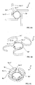
- A cable reel of reverse type for installation on the steering apparatus of a vehicle, as shown in Figs. 8A and 8B, has been proposed. Similar cable reels are disclosed in JP-A-177968. In the cable reel of Figs. 8A and 8B, a
stationary member 19 serving as an outer cylinder is fixed to a steering column (not shown), and amovable member 12 serving as an inner cylinder is fixed to a steering wheel (not shown). Thestationary member 19 and themovable member 12 are connected to each other relatively rotatably. An annularrotary ring 17 made of synthetic resin is freely rotatably accommodated in the annularhollow space 18 formed by thestationary member 19 and themovable member 12.Reverse rings rotary ring 17. - In the annular
hollow space 18,flat cables movable member 12 are wound in a space C5 disposed between themovable member 12 and thereverse rings reverse rings flat cables stationary member 19 and thereverse rings flat cables stationary member 19. - In this cable reel, when a steering handle or steering wheel is rotated in one direction, the
flat cables reverse rings rings flat cables movable member 12. On the other hand, when the steering handle or steering wheel is rotated in the opposite direction, the rewoundflat cables flat cables reverse rings stationary member 19. - In the cable reel described above, the
reverse rings flat cables reverse rings hollow space 18, thereverse rings rotary ring 17. That is, to construct the member for reversing the flat cable, three parts are required. These are the tworeverse rings rotary ring 17. - With an increase of the number of flat cables in such a cable reel, it is necessary to increase the number of reverse rings, which leads to an increase in the number of component parts and makes the manufacturing cost to be high.
- The
reverse rings rotary ring 17 and thus they are incapable of moving in directions other than the rotary direction. Further, because thereverse rings stationary member 18 and each of thereverse rings movable member 12 and each of thereverse rings - Accordingly, with an increase in the number of flat cables which pass through each space C5, C6 due to the rotation of the
movable member 12, the width of each space is set, e.g. during manufacture by adding an allowance thereto, i.e. each space is made wider if the cable reel carries a larger number of bundles of flat cables. This has the defect that theflat cables movable member 12. As a result, theflat cables - The present invention seeks to reduce or avoid the above-described problem. Accordingly, it is an object of the present invention to reduce the number of component parts in a cable reel of reverse type. A further object is to reduce or prevent generation of vibrations and/or abnormal sounds when a movable member rotates, by improving members for reversing a flat cable which is accommodated in an annular hollow space of a cable reel of reverse type.
- Accordingly, the present invention provides a cable reel comprising:
- a stationary member;
- a rotatable member located with respect to said stationary member so as to define an annular hollow space between said rotatable and stationary members;
- a reverse member accommodated in said annular hollow space, said reverse member including a plurality of reverse portions and an annular member, said reverse member being formed in one piece from a sheet;
- a flat cable accommodated in said annular hollow space, said flat cable having respective spaced portions fixed with respect to said stationary member and with respect to said rotatable member and an intermediate portion between said spaced portions which is wound on one of said reverse portions.
-
- Preferably the sheet is resiliently flexible.
- Preferably, said reverse portions are radially expansible loops formed so as to press part of the intermediate portion of the flat cable against the stationary member. Typically, each reverse portion is formed by looping an arm projecting from the annular member. Each arm may have a fixed end fixed to the annular member and a free end, said free end being slidably movable with respect to said fixed end. Alternatively, each arm may have a fixed end fixed to the annular member and a free end, said free end being engageable with the fixed end in order to retain the loop. In that case, the free end of the arm may be engageable with or lockable to the fixed end of the arm via a slot.
- The annular member may be disposed centrally of circumferential arm projections which are bent and looped to form the reverse portions.
- Preferably, the arm projections are L-shaped.
- Each L-shaped arm projection may include a short transverse portion and a long longitudinal portion, the transverse portion connecting the longitudinal portion to the annular member. The slot may be formed on the longitudinal portion, near the fixed end of the arm.
- Preferably, to form one of the reverse portions, the transverse portion is bent perpendicularly to the central annular member and the longitudinal portion is looped to form one of the reverse portions. The part of the flat cable wound on each reverse portion may be sandwiched between the outer surface of each reverse ring and the outer wall of the annular hollow portion and, optionally, between the adjacent reverse rings. Thus when the flat cable moves with the rotation of the movable member, it can be difficult for the flat cable to move freely. This can assist in the suppression of the generation of vibrations and abnormal sounds.
- Typically, the central annular member serves as a rotary ring and is disposed on a bottom surface of the annular hollow space. A gap between an inner peripheral surface of each reverse portion and a peripheral surface of the movable member may be identified as an inner peripheral passage for each flat cable to be fixed with respect to the movable member. A gap between the reverse portions adjacent to each other circumferentially may be identified as a reversing passage for each flat cable. A gap between a peripheral surface of each reverse portion and an inner peripheral surface of the stationary member may be identified as an outer peripheral passage for each flat cable.
- In use, the rotary ring rotates with the rotation of each reverse ring because the rotary ring is integral with the reverse rings. Thus the rotary ring holds the position of the reverse rings, thus holding the reverse rings in the annular hollow space, with the reverse rings spaced at equal intervals.
- In preferred embodiments, the reverse member is freely rotatable within the cable reel. That is, the reverse member is not fixed with respect to the rotary member or fixed member. Rotation of the reverse member typically occurs due to tension in the flat cables during winding of the flat cables into the inner peripheral passage. Rotation of the reverse member in the other direction may occur since the flat cables are preferably rigid enough to be capable of pushing the reverse portions during unwinding of the flat cables from the inner peripheral passage.
- When the flat cable is wound tightly, the number of turns of the flat cable usually increases. In that case it may be necessary to increase the width of the inner peripheral passage to accommodate the flat cable. However, in the case where each reverse portion is flexible, the width of the inner peripheral passage is widened according to the number of turns of the flat cable. In this way, it is possible to ensure smooth operation of tight winding of the flat cable.
- The flexible sheet is preferably an insulating plastics material sheet. By using an insulating plastics material sheet, it is possible to manufacture a reverse member light in weight and at a low cost which is capable of securely insulating the flat cables in contact with the reverse ring.
- Bending of the insulating plastics material sheet may be facilitated by making a bending portion thin. Preferably, the bending applied to the plastics material sheet is not a fully permanent deformation. However, the bending may leave the plastics material with a partial permanent deformation.
- It is preferable to provide four reverse portions in the annular hollow space.
- Of course, when four reverse portions are disposed in the annular hollow space, they can be used in any case where, e.g. one, two, three or four flat cables are used.
- When four reverse portions are disposed in the annular hollow portion, it is preferable that each of the four reverse portions (or rings) contacts the flat cable over a sufficient area to ensure that when the movable member rotates, the flat cable has a stable locus.
- The number of the reverse portions is not limited to four but one, two or three reverse rings may be used.
- In another preferred embodiment, the present invention provides a cable reel comprising:
- a stationary member;
- a rotatable member located with respect to said stationary member so as to define an annular hollow space between said rotatable and stationary members;
- a reverse member accommodated in said annular hollow space, said reverse member being formed in one piece from a flexible sheet and including a plurality of reverse portions and an annular member, the annular member being disposed centrally of the reverse portions, each reverse portion being formed by bending and looping an L-shaped arm projection which is disposed at a circumference of said annular member;
- a flat cable accommodated in said annular hollow space, said flat cable having respective spaced portions fixed with respect to said stationary member and with respect to said rotatable member and an intermediate portion between said spaced portions which is wound on one of said reverse portions.
-
- In another aspect, the present invention provides a method of forming a cable reel including the formation of a reverse member, wherein the reverse member has a plurality of reverse portions and a central annular member, the reverse portions being disposed at regular intervals in a circumferential direction around said central annular member,
said reverse member being formed in one piece from a flexible sheet, the method including the step of bending and looping arm projections to form said plurality of reverse portions. - In another preferred embodiment, the sheet is an annular sheet and the reverse portions are projections from a surface of the annular member, the projections being formed by moulding of the annular sheet.
- Preferably, the moulding operation gives reverse portions of a kidney shape. Preferably, the moulding is vacuum moulding. The reverse portions may be radially resiliently flexible.
- Again, preferably the sheet is an insulating plastics material sheet.
- As mentioned above, a reverse member including a plurality of the reverse portions may be formed in one piece by vacuum moulding of an annular sheet. Thus the reverse member which is accommodated in the annular hollow space may be a single component. In this way the number of component parts may be reduced.
- The number of the flat cable-reversing portions required in the cable reel increases with the number of flat cables. However, since a plurality of reverse portions may be formed from one flexible sheet, it is possible to form the required number of reverse portions as a single reverse member component. Therefore it is possible to reduce the number of component parts in the cable reel.
- The formation of the reverse portions may be completed at the time of vacuum moulding. Assembly of the cable reel may be facilitated since the reverse portions are formed on the reverse member prior to assembly, so that it is only necessary simply to insert the reverse member into the annular hollow portion.
- In a preferred embodiment, the present invention provides a cable reel comprising:
- a stationary member;
- a rotatable member located with respect to said stationary member so as to define an annular hollow space between said rotatable and stationary members;
- a reverse member accommodated in said annular hollow space, said reverse member being formed by vacuum moulding from an annular sheet to give an annular member with moulded projections from a surface of the annular member, the projections being disposed at regular intervals in a circumferential direction around said annular member, each moulded projection being a reverse portion;
- a flat cable accommodated in said annular hollow space, said flat cable having respective spaced portions fixed with respect to said stationary member and with respect to said rotatable member and an intermediate portion between said spaced portions which is wound on one of said reverse portions.
-
- In a further aspect, the present invention provides a method of forming a cable reel including the formation of a reverse member, wherein the reverse member has a plurality of reverse portions and an annular member, the reverse portions being disposed in a circumferential direction around said annular member,
the reverse member being formed in one piece by moulding of an annular sheet to give the reverse portions which project from a surface of the annular member. - In another aspect, the present invention provides a vehicle having a steering assembly including a cable reel according to any one of the above aspects.
- Embodiments of the invention will now be described by way of non-limitative example with reference to the drawings, in which:-
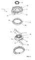
- Fig. 1 is an exploded perspective view of component parts of a cable reel which is a first embodiment of the present invention.
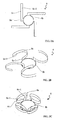
- Figs. 2A, 2B and 2C show a process of forming a reverse member of the cable reel of the first embodiment, in which Fig. 2A is a view showing a punched sheet to form the reverse member and Figs. 2B and 2C are perspective views each showing a bending process.
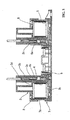
- Fig. 3 is a vertical sectional view of the cable reel of the first embodiment.
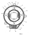
- Fig. 4 is a horizontal sectional view of the cable reel of the first embodiment.
- Fig. 5 is a perspective view of the cable reel of the first embodiment when the cable reel is viewed from above.
- Figs. 6A, 6B and 6C show a process of forming a reverse member of a cable reel of a second embodiment of the invention, in which Fig. 6A is a view of a punched sheet to form the reverse member and Figs. 6B and 6C are perspective views each showing a bending process.
- Figs. 7A and 7B show a reverse member of a cable reel of a third embodiment of the invention, in which Fig. 7A is a perspective view in which the reverse member is viewed from above, and Fig. 7B is a perspective view in which the reverse member is viewed from below.
- Fig. 8A is a horizontal sectional view of a known cable reel described above and Fig. 8B is a perspective view showing a flat cable-reversing member of the known cable reel of Fig. 8A.
-
- A cable reel of the present invention is described below with reference to Figs. 1 to 5. A rotor 3 (rotatable or movable member) serving as an inner cylinder is relatively rotatably connected to a base case (stationary member) 7 serving as an outer cylinder. The
base case 7 is fixed to a steering column (not shown) and has aperipheral wall 7a projecting from the periphery of anannular bottom wall 7b. Therotor 3 is fixed to a steering wheel and has a closedportion 3d projecting from the periphery of one end surface of acylindrical portion 3a. - A
reverse member 6 having fourreverse rings 6a continuous with the periphery of arotary ring 6b is accommodated in an annularhollow space 8 between thebase case 7 and therotor 3 in such a way that therotary ring 6b is freely rotatable with respect to the inner and outer walls of the annularhollow space 8. The annularhollow space 8 accommodatesflat wiring cables connector portions rotor 3 respectively, with theflat cables connector accommodation portion 7c fixed to thebase case 7 accommodatesconnectors flat cables - The
flat wiring cables - The
rotor 3 has atop cover 9 and a lockingmember 2 fixes therotor 3 to a steering shaft (not shown). - The
reverse member 6 is formed in a flat shape from a resiliently flexible electrically insulating plastics material sheet and bending it into the required configuration. The thickness of this sheet is preferably in the range 0.1 to 1.0mm and more preferably 0.4 to 0.6mm to allow thereverse member 6 to be suitably flexible. Any suitable materials can be used to form the sheet so long as they are flexible and resilient (preferably with electrically insulating properties). A polypropylene sheet is preferably used because it is lightweight and inexpensive. - As shown in Fig. 2A, the insulating sheet is punched into a configuration having the annular
rotary ring 6b (central annular portion) and four inverted L-shapedarms 6c projecting from the periphery of therotary ring 6b at regular intervals in its circumferential direction. Each of the L-shapedarms 6c has a shorttransverse portion 6c-1 continuous with therotary ring 6b and a longlongitudinal portion 6c-2 continuous with thetransverse portion 6c-1 and perpendicular to thetransverse portion 6c-1. - The sheet punched in the configuration as shown in Fig. 2A is then bent so that each
arm 6c is bent upwardly perpendicularly at thetransverse portion 6c-1. Thearm 6c is curved to a closed loop in such a way that the surface of thelongitudinal portion 6c-2 confronting the centre of therotary ring 6b is disposed at the outer side of the rotary ring. In this manner, four upstanding reverse rings 6a are formed, as shown in Fig. 2C. In the first embodiment, the free end of thelongitudinal portion 6c-2 is in excess in length and is not fixed but overlaps the near end of thereverse ring 6a when accommodated in the annularhollow space 8 to keep thereverse ring 6a as a closed loop of kidney shape. - The
reverse member 6 obtained by bending the flat sheet is accommodated in the annularhollow space 8. The gap between the upper surface of therotary ring 6b, namely, the peripheral surface of therotor 3 and the inner peripheral surface of eachreverse ring 6a provides an inner peripheral passage C2 for theflat cables base case 7 and the peripheral surface of eachreverse ring 6a provides a peripheral outer passage C1 for the flat cables. - More specifically, with one end of the
flat cables connector portions rotor 3 respectively, theflat cables flat cables flat cables connector accommodation portion 7c accommodates theconnectors flat cables - Further because the
reverse member 6 has fourreverse rings 6a, thereverse member 6 can be used in any of the cases where the required number of the flat cables is one, two, three or four. Thus it is not necessary to provide the reverse member in accordance with the number of the flat cables. That is, it is possible to reduce the number of parts. - The rotating operation of the
cable reel 1 of the first embodiment will be described below. - When the
rotor 3 rotates in unison with the rotation of the steering wheel (not shown), theflat cables rotor 3 are operated in unison with the rotation of therotor 3. - When the
rotor 3 is rotated counterclockwise as seen in Fig. 4, a portion of each of theflat cables flat cables - On the other hand, when the
rotor 3 is rotated in the reverse direction, namely clockwise, most of the length of theflat cables - Because the
reverse ring 6a is made of a resilient plastics sheet, it has a restoring force urging it to a flat configuration. That is, thereverse ring 6a in the annularhollow space 8 tends to expand radially so as always to minimise the width of each of the outer peripheral passage C1 and the inner peripheral passage C2. - Therefore, when the
rotor 3 rotates, theflat cables flat cables - The free end of the
longitudinal portion 6c-2 is not fixed to thereverse ring 6a but is elongated. Thus the diameter (radial dimension) of thereverse ring 6a can be flexibly enlarged or reduced with the reciprocation of theflat cables rotor 3. - In the first embodiment, although the cable reel has two flat cables, the
flat cables flat cables reverse rings 6a. Therefore, it is easy to stabilize the rotary locus of theflat cables - The cable reel of the second embodiment of Fig. 6 is similar to that of the first embodiment except for the construction of the reverse member 6' of the second embodiment. Other parts will not be described again.
- The reverse member 6' of the second embodiment is different from the
reverse member 6 of the first embodiment in that the extremity of thearm 6c' which constitutes eachreverse ring 6c' of the second embodiment is locked at a locking portion. - More specifically, as shown in Fig. 6A, the insulating plastics material sheet is punched to give a shape having a
rotary ring 6b' and four L-shapedarms 6c' projecting from the periphery of therotary ring 6b' at regular intervals in its circumferential direction. Each of thearms 6c' has a shorttransverse portion 6c-1' continuous with therotary ring 6b', a longlongitudinal portion 6c-2' continuous with thetransverse portion 6c-1' and perpendicular thereto, and alocking slot 6c-3' in the form of a notch on a portion of thelongitudinal portion 6c-2' at the side of thetransverse portion 6c-1'. Theslot 6c-3' is perpendicular to the longitudinal direction of thelongitudinal portion 6c-2'. - As shown in Fig. 6B, each
arm 6c' is bent upward at thetransverse portion 6c-1' to be perpendicular to therotary ring 6b'. Then eacharm 6c' is curved cylindrically in such a way that the surface of eachlongitudinal portion 6c-2' facing the centre of therotary ring 6b' is the outer surface of thearm 6c'. Thereafter, as shown in Fig. 6C, the extremity of thelongitudinal portion 6c-2' is inserted into theslot 6c-3' and thus locked thereto. Thus it is easy to form the fourreverse rings 6a. - Since the
longitudinal portion 6c-2' is locked at theslot 6c-3', it is prevented from restoring itself to a flat configuration. Thus it is easy to perform an assembling operation when inserting the reverse rings 6a' in the annularhollow space 8. - Each
reverse ring 6a' is flexible and resilient. Thus when it is locked at theslot 6c-3', it has a restoring force urging it back towards a circular configuration from an elliptic configuration. That is, this restoring force acts to minimise the width of each of the outer peripheral passage C1, the inner peripheral passage C2. Similarly to the first embodiment, when therotor 3 rotates, theflat cables
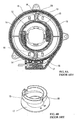
Accordingly, theflat cables - The cable reel of the third embodiment of Fig. 7 is similar to that of the first and second embodiments except in the construction of the
reverse member 6" in the annularhollow space 8. Other parts will not be described again. - As shown in Fig. 7, the
reverse member 6" has four ellipticallycurved reverse portions 6a" formed by vacuum-moulding an annular plastics material sheet, the fourreverse portions 6a being spaced at regular intervals in the circumferential direction of themember 6". Themember 6" has a planar peripheral flange providing an outerannular portion 6c" between its outer periphery and thereverse portions 6a" and an innerannular portion 6b" between its inner periphery and thereverse portions 6a". - This construction allows the formation of the
reverse member 6" to be completed by vacuum moulding, and permits thereverse member 6" to be simply inserted into the annularhollow space 8, with the projectingreverse portions 6a" disposed at the upward side. That is, it is easy to perform the assembly work. - For the passage of the
flat cables hollow space 8, the gap between the upper surface of the innerannular portion 6b", the peripheral surface of therotor 3 and the inner peripheral surface of eachreverse portion 6a" forms the inner peripheral passage C2; each gap (four gaps in total) between thereverse portions 6a circumferentially adjacent to each other provides the reverse passage C3; and the gap between the upper surface of the outerannular portion 6c", the inner peripheral surface of thebase case 7 and the peripheral surface of eachreverse portion 6a" provides the outer peripheral passage C1. - By setting the width of the inner peripheral passage C2, the outer peripheral passage C1, and the reverse passage C3 without providing an allowance, it is possible for the above construction to suppress the free movement of the
flat cables flat cables flat cables reverse portion 6a" is flexible and thus capable of flexing inward. -
Reverse portions 6a" are kidney-shaped and are radially (i.e. in directions within the plane of the planar peripheral flange) resiliently flexible. Thus, thereverse portions 6a" may be distorted in this direction by flat cables sandwiched between theportions 6a" and the inner peripheral surface of the base case. In this way, the flat cables are sandwiched and pressed by theresilient reverse portions 6a". - As in the case of the first and second embodiments, the third embodiment has the effect of reducing the number of component parts.
- As will be apparent from the foregoing description of the first and second embodiments, the flat cable-reversing member which is accommodated in the annular hollow space of the cable reel may be formed in one piece from a flexible sheet. Thus a plurality of the reverse loops are formed from one piece of material. In this way it is possible to reduce the number of component parts and manufacturing cost. Further, assembly is easy and time and labour are reduced. In particular, when the reverse loops are formed from insulating sheet, it is possible to securely insulate the flat cables.
- Each reverse loop is made of the resilient flexible plastics sheet curved in a kidney shape when assembled in the cable reel. Each loop is radially expansible. Thereby each flat cable is sandwiched between the outer surface of a reverse loop and the inner surface of the annular hollow space and pressed between them. When the flat cable is wound, this sandwiching makes it difficult for it to move freely in a direction perpendicular to its winding direction. Thus it is possible to suppress generation of vibrations and abnormal sounds.
- In the second embodiment the end of each of the reverse loops is inserted into and locked at the slot formed at the base end portion of the arm of the ring. Thereby it is easy to ensure that the reverse loop keeps its cylindrical configuration. Thus it is easy to perform an assembling operation when accommodating the reverse loop in the annular hollow space.
- In the third embodiment, by forming a plurality of the reverse portions integrally by vacuum moulding of an annular sheet, a single member is accommodated in the annular hollow space. Thus it is possible to reduce the number of component parts. In this case, the formation of the reverse portions is completed at the time of vacuum moulding, and it is easy to perform the assembling work.
- While the invention has been described in conjunction with the exemplary embodiments described above, many equivalent modifications and variations will be apparent to those skilled in the art when given this disclosure. Accordingly, the exemplary embodiments of the invention set forth above are considered to be illustrative and not limiting. Various changes to the described embodiments may be made without departing from the spirit and scope of the invention.
Claims (18)
- A cable reel (1) comprising:characterised in that:a stationary member (7);a rotatable member (3) located with respect to said stationary member so as to form an annular hollow space (8) between them;a reverse member (6, 6', 6") having an annular member (6b, 6b', 6b"), anda plurality of reverse portions (6a, 6a', 6a") accommodated in said annular hollow space (8) ;a flat cable (4) accommodated in said annular hollow space and having respective spaced portions fixed with respect to said stationary member (7) and with respect to said rotatable member (3), and an intermediate portion between said spaced portions wound on one of said reverse portions,said reverse member including said plurality of reverse portions and said annular member (6b, 6b") are formed in one piece from a sheet.
- A cable reel according to claim 1, wherein the sheet is resiliently flexible.
- A cable reel according to claim 1 or claim 2, wherein said reverse portions are radially expansible loops formed so as to press part of the intermediate portion of the flat cable against the stationary member.
- A cable reel according to any one of claims 1 to 3, wherein each reverse portion is formed by looping an arm projecting from the annular member.
- A cable reel according to claim 4, wherein the arm has a fixed end fixed to the annular member and a free end, said free end being slidably movable with respect to said fixed end.
- A cable reel according to claim 4, wherein the arm has a fixed end fixed to the annular member and a free end, said free end being engageable with the fixed end in order to retain the loop.
- A cable reel according to claim 6, wherein the free end of the arm is lockable to the fixed end of the arm via a slot.
- A cable reel according to any one of claims 4 to 7, wherein the arm projections (6c) are L-shaped.
- A cable reel according to claim 8, wherein, for each L-shaped arm projection (6c), a short transverse portion (6c-1) of the L-shape connects the central annular member to a long longitudinal portion (6c-2) of the L-shape.
- A cable reel according to claim 9, wherein, for each L-shaped arm projection, the transverse portion (6c-1) is bent perpendicularly to the central annular member (6b) and the longitudinal portion (6c-2) is looped to form one of the reverse portions (6a).
- A cable reel according to any one of claims 1 to 10, wherein the annular member (6b) is disposed centrally of the reverse portions.
- A cable reel according to claim 1 or claim 2, wherein the sheet is an annular sheet and the reverse portions (6a") are projections from a surface of the annular member (6b", 6c"), being formed by moulding of the annular sheet.
- A cable reel according to claim 12, wherein the moulding is vacuum moulding.
- A cable reel according to any one of claims 1 to 13, wherein the sheet is an insulating plastic material sheet.
- A cable reel according to any one of claims 1 to 14, wherein the reverse member has four reverse portions (6a, 6a' 6a").
- A vehicle having a steering assembly with a cable reel according to any one of claims 1 to 15.
- A method of forming a cable reel (1) including the formation of a reverse member (6, 6') having a plurality of reverse loops (6a, 6a') integral with and disposed at regular intervals in a circumferential direction around a central annular member (6b, 6b'),
the reverse member being formed from a flexible sheet, the method including the step of bending and looping arm projections (6c, 6c') to form said plurality of reverse loops. - A method of forming a cable reel (1) including the formation of a reverse member (6") having a plurality of reverse portions (6a") disposed in a circumferential direction around an annular member (6b"),
the reverse member (6") being formed by moulding of an annular sheet to give the reverse portions (6a") which are projections from a surface of the annular member (6b").
Applications Claiming Priority (2)
| Application Number | Priority Date | Filing Date | Title |
|---|---|---|---|
| JP2001038697 | 2001-02-15 | ||
| JP2001038697A JP2002247746A (en) | 2001-02-15 | 2001-02-15 | Cable reel |
Publications (2)
| Publication Number | Publication Date |
|---|---|
| EP1232914A2 true EP1232914A2 (en) | 2002-08-21 |
| EP1232914A3 EP1232914A3 (en) | 2003-10-22 |
Family
ID=18901622
Family Applications (1)
| Application Number | Title | Priority Date | Filing Date |
|---|---|---|---|
| EP02250980A Withdrawn EP1232914A3 (en) | 2001-02-15 | 2002-02-13 | Cable reel |
Country Status (3)
| Country | Link |
|---|---|
| US (1) | US6572393B2 (en) |
| EP (1) | EP1232914A3 (en) |
| JP (1) | JP2002247746A (en) |
Cited By (2)
| Publication number | Priority date | Publication date | Assignee | Title |
|---|---|---|---|---|
| EP2048038A1 (en) * | 2007-10-11 | 2009-04-15 | Nexans | Device for signal and current transmission between terminals moveable in relation to each other |
| EP3392991A4 (en) * | 2015-12-17 | 2019-03-20 | Furukawa Electric Co., Ltd. | RIBBON ASSEMBLY, ROTARY CONNECTOR, AND METHOD FOR PRODUCING RIBBON ASSEMBLY |
Families Citing this family (19)
| Publication number | Priority date | Publication date | Assignee | Title |
|---|---|---|---|---|
| JP4002166B2 (en) * | 2002-11-13 | 2007-10-31 | 古河電気工業株式会社 | Relay device |
| US7104821B2 (en) * | 2004-09-16 | 2006-09-12 | Alps Electric Co., Ltd. | Rotary connector |
| ATE395217T1 (en) * | 2005-11-25 | 2008-05-15 | Nexans | DEVICE FOR SIGNAL OR POWER TRANSMISSION BETWEEN TERMINAL POINTS |
| JP5123071B2 (en) * | 2008-06-19 | 2013-01-16 | ナイルス株式会社 | Rotating connector device |
| KR101061989B1 (en) | 2008-12-03 | 2011-09-05 | (주)신창코넥타 | Spacer and vehicle clock spring device including the spacer |
| US8238707B2 (en) | 2009-07-30 | 2012-08-07 | Adc Telecommunications, Inc. | Locking spool for telecommunications cable and method |
| US8474742B2 (en) * | 2009-07-30 | 2013-07-02 | Adc Telecommunications, Inc. | Spool for telecommunications cable and method |
| US7758364B1 (en) * | 2009-08-04 | 2010-07-20 | Seagate Technology Llc | Rotary positioning |
| US8720810B2 (en) | 2011-02-11 | 2014-05-13 | Adc Telecommunications, Inc. | Spool for telecommunications cable and method |
| US10150071B2 (en) * | 2011-04-18 | 2018-12-11 | Bulk Tank, Inc. | Filter guide ring |
| EP2845281A4 (en) * | 2012-04-30 | 2015-12-23 | Adc Telecommunications Inc | Cable storage spool with center feed |
| US9722407B2 (en) | 2012-04-30 | 2017-08-01 | Commscope Technologies Llc | Guided cable storage assembly with switchbacks |
| US9126802B2 (en) | 2012-04-30 | 2015-09-08 | Adc Telecommunications, Inc. | Payout spool with automatic cable disconnect/reconnect |
| WO2013165899A1 (en) | 2012-04-30 | 2013-11-07 | Adc Telecommunications, Inc. | Cable payout cassette with single layer cable storage area |
| CN106477058B (en) * | 2016-12-29 | 2019-02-01 | 昊翔电能运动科技(昆山)有限公司 | Anti- torsion component, holder and aircraft |
| EP3744972B1 (en) * | 2019-05-27 | 2023-01-11 | Siemens Gamesa Renewable Energy A/S | Rotor for a wind turbine and wind turbine |
| JP7654660B2 (en) * | 2020-07-13 | 2025-04-01 | 古河電気工業株式会社 | Rotating Connector Device |
| KR20230035637A (en) * | 2020-07-15 | 2023-03-14 | 후루카와 덴키 고교 가부시키가이샤 | swivel connector device |
| CN118099881A (en) * | 2024-04-15 | 2024-05-28 | 深圳市宝奕科技有限公司 | A retractable slip ring power transmission mechanism |
Citations (1)
| Publication number | Priority date | Publication date | Assignee | Title |
|---|---|---|---|---|
| JPS6477968A (en) | 1987-09-19 | 1989-03-23 | Fujitsu Ltd | Semiconductor device |
Family Cites Families (15)
| Publication number | Priority date | Publication date | Assignee | Title |
|---|---|---|---|---|
| JPH06333660A (en) | 1993-05-26 | 1994-12-02 | Furukawa Electric Co Ltd:The | Rotary connector |
| DE4436972A1 (en) * | 1994-10-15 | 1996-04-18 | Kabelmetal Electro Gmbh | Device for signal transmission between two end points |
| JPH08222340A (en) * | 1994-12-14 | 1996-08-30 | Yazaki Corp | Electrical connection device between steering wheel and steering column |
| JPH08185950A (en) * | 1995-01-05 | 1996-07-16 | Yazaki Corp | Fixing structure of flat cable to cylindrical rotating body |
| US5580259A (en) * | 1995-02-10 | 1996-12-03 | Methode Electronics, Inc. | Clockspring with resilient flat cable carrier apparatus |
| JPH08306458A (en) | 1995-05-02 | 1996-11-22 | Yazaki Corp | Electrical connection device between rotating body and fixed body |
| US5645441A (en) * | 1995-05-18 | 1997-07-08 | Niles Parts Co., Ltd. | Rotary connector device |
| JPH0955274A (en) | 1995-08-11 | 1997-02-25 | Yazaki Corp | Electrical connection device between rotating body and fixed body |
| JPH09274981A (en) * | 1995-08-11 | 1997-10-21 | Yazaki Corp | Relay device between relative rotating members |
| JPH1055867A (en) * | 1996-08-09 | 1998-02-24 | Furukawa Electric Co Ltd:The | Rotating connector |
| JPH1092542A (en) * | 1996-09-13 | 1998-04-10 | Yazaki Corp | Relay device between relative rotating members |
| JPH10162921A (en) | 1996-12-02 | 1998-06-19 | Tokai Rika Co Ltd | Steering roll connector |
| JP3713910B2 (en) * | 1997-07-11 | 2005-11-09 | 松下電器産業株式会社 | Rotating connector |
| JP3518995B2 (en) * | 1998-07-02 | 2004-04-12 | アルプス電気株式会社 | Rotating connector |
| JP3518673B2 (en) * | 1999-06-23 | 2004-04-12 | アルプス電気株式会社 | In-vehicle rotary connector |
-
2001
- 2001-02-15 JP JP2001038697A patent/JP2002247746A/en not_active Withdrawn
-
2002
- 2002-01-24 US US10/053,961 patent/US6572393B2/en not_active Expired - Fee Related
- 2002-02-13 EP EP02250980A patent/EP1232914A3/en not_active Withdrawn
Patent Citations (1)
| Publication number | Priority date | Publication date | Assignee | Title |
|---|---|---|---|---|
| JPS6477968A (en) | 1987-09-19 | 1989-03-23 | Fujitsu Ltd | Semiconductor device |
Cited By (2)
| Publication number | Priority date | Publication date | Assignee | Title |
|---|---|---|---|---|
| EP2048038A1 (en) * | 2007-10-11 | 2009-04-15 | Nexans | Device for signal and current transmission between terminals moveable in relation to each other |
| EP3392991A4 (en) * | 2015-12-17 | 2019-03-20 | Furukawa Electric Co., Ltd. | RIBBON ASSEMBLY, ROTARY CONNECTOR, AND METHOD FOR PRODUCING RIBBON ASSEMBLY |
Also Published As
| Publication number | Publication date |
|---|---|
| JP2002247746A (en) | 2002-08-30 |
| US6572393B2 (en) | 2003-06-03 |
| US20020111056A1 (en) | 2002-08-15 |
| EP1232914A3 (en) | 2003-10-22 |
Similar Documents
| Publication | Publication Date | Title |
|---|---|---|
| US6572393B2 (en) | Cable reel | |
| KR100906235B1 (en) | Rotary electric machine with coil member and method of manufacturing coil member | |
| US5252085A (en) | Clock spring connector | |
| US7104821B2 (en) | Rotary connector | |
| EP0641288B1 (en) | Improved cord take-up device | |
| KR20170092391A (en) | Motor | |
| WO2011122470A1 (en) | Rotary connector device | |
| US5937076A (en) | Magnetic drive apparatus and method for manufacturing coil that forms the apparatus | |
| JP3016898B2 (en) | Cable reel | |
| KR980012733A (en) | Swivel Connector | |
| JP2502993Y2 (en) | Cable reel | |
| KR100454401B1 (en) | Rotary connector | |
| JP2009278864A (en) | Stator of electric rotating machine | |
| US5707023A (en) | Apparatus for establishing electrical connection between rotor and fixed member | |
| JPH0717338A (en) | Cable reel | |
| KR100419490B1 (en) | A signal transmission device between two terminals | |
| JP2006086044A (en) | Rotary connector | |
| CN103262363B (en) | Rotary connector | |
| JP3153740B2 (en) | Electrical connection device between fixed body and rotating body | |
| US5026289A (en) | Clock spring interconnector for steering | |
| JPH0738299Y2 (en) | Cable reel | |
| JP2702626B2 (en) | Cable reel | |
| JP5867835B2 (en) | Rotating connector | |
| JP2774720B2 (en) | Cable reel | |
| JP2534319Y2 (en) | Cable reel |
Legal Events
| Date | Code | Title | Description |
|---|---|---|---|
| PUAI | Public reference made under article 153(3) epc to a published international application that has entered the european phase |
Free format text: ORIGINAL CODE: 0009012 |
|
| 17P | Request for examination filed |
Effective date: 20020304 |
|
| AK | Designated contracting states |
Kind code of ref document: A2 Designated state(s): AT BE CH CY DE DK ES FI FR GB GR IE IT LI LU MC NL PT SE TR |
|
| AX | Request for extension of the european patent |
Free format text: AL;LT;LV;MK;RO;SI |
|
| PUAL | Search report despatched |
Free format text: ORIGINAL CODE: 0009013 |
|
| AK | Designated contracting states |
Kind code of ref document: A3 Designated state(s): AT BE CH CY DE DK ES FI FR GB GR IE IT LI LU MC NL PT SE TR |
|
| AX | Request for extension of the european patent |
Extension state: AL LT LV MK RO SI |
|
| AKX | Designation fees paid | ||
| REG | Reference to a national code |
Ref country code: DE Ref legal event code: 8566 |
|
| STAA | Information on the status of an ep patent application or granted ep patent |
Free format text: STATUS: THE APPLICATION IS DEEMED TO BE WITHDRAWN |
|
| 18D | Application deemed to be withdrawn |
Effective date: 20040423 |