EP1232322B1 - Rohrverbindung - Google Patents
Rohrverbindung Download PDFInfo
- Publication number
- EP1232322B1 EP1232322B1 EP00984830A EP00984830A EP1232322B1 EP 1232322 B1 EP1232322 B1 EP 1232322B1 EP 00984830 A EP00984830 A EP 00984830A EP 00984830 A EP00984830 A EP 00984830A EP 1232322 B1 EP1232322 B1 EP 1232322B1
- Authority
- EP
- European Patent Office
- Prior art keywords
- contact surface
- tube connection
- sleeve
- shoulder
- plug
- Prior art date
- Legal status (The legal status is an assumption and is not a legal conclusion. Google has not performed a legal analysis and makes no representation as to the accuracy of the status listed.)
- Expired - Lifetime
Links
- 238000007789 sealing Methods 0.000 claims description 29
- 230000001419 dependent effect Effects 0.000 claims description 2
- 239000000463 material Substances 0.000 claims description 2
- 239000008186 active pharmaceutical agent Substances 0.000 description 7
- 238000005452 bending Methods 0.000 description 2
- 230000006835 compression Effects 0.000 description 2
- 238000007906 compression Methods 0.000 description 2
- 238000010276 construction Methods 0.000 description 2
- 238000005553 drilling Methods 0.000 description 2
- 238000009434 installation Methods 0.000 description 2
- 238000004519 manufacturing process Methods 0.000 description 2
- 230000007704 transition Effects 0.000 description 2
- 241000196324 Embryophyta Species 0.000 description 1
- 241001295925 Gegenes Species 0.000 description 1
- 235000008331 Pinus X rigitaeda Nutrition 0.000 description 1
- 235000011613 Pinus brutia Nutrition 0.000 description 1
- 241000018646 Pinus brutia Species 0.000 description 1
- 239000004809 Teflon Substances 0.000 description 1
- 229920006362 Teflon® Polymers 0.000 description 1
- 230000002411 adverse Effects 0.000 description 1
- 150000001875 compounds Chemical class 0.000 description 1
- 238000011161 development Methods 0.000 description 1
- 230000018109 developmental process Effects 0.000 description 1
- 230000000694 effects Effects 0.000 description 1
- 239000004519 grease Substances 0.000 description 1
- 230000036316 preload Effects 0.000 description 1
- 230000035939 shock Effects 0.000 description 1
- XLYOFNOQVPJJNP-UHFFFAOYSA-N water Substances O XLYOFNOQVPJJNP-UHFFFAOYSA-N 0.000 description 1
Images
Classifications
-
- F—MECHANICAL ENGINEERING; LIGHTING; HEATING; WEAPONS; BLASTING
- F16—ENGINEERING ELEMENTS AND UNITS; GENERAL MEASURES FOR PRODUCING AND MAINTAINING EFFECTIVE FUNCTIONING OF MACHINES OR INSTALLATIONS; THERMAL INSULATION IN GENERAL
- F16L—PIPES; JOINTS OR FITTINGS FOR PIPES; SUPPORTS FOR PIPES, CABLES OR PROTECTIVE TUBING; MEANS FOR THERMAL INSULATION IN GENERAL
- F16L15/00—Screw-threaded joints; Forms of screw-threads for such joints
- F16L15/001—Screw-threaded joints; Forms of screw-threads for such joints with conical threads
- F16L15/004—Screw-threaded joints; Forms of screw-threads for such joints with conical threads with axial sealings having at least one plastically deformable sealing surface
-
- E—FIXED CONSTRUCTIONS
- E21—EARTH OR ROCK DRILLING; MINING
- E21B—EARTH OR ROCK DRILLING; OBTAINING OIL, GAS, WATER, SOLUBLE OR MELTABLE MATERIALS OR A SLURRY OF MINERALS FROM WELLS
- E21B17/00—Drilling rods or pipes; Flexible drill strings; Kellies; Drill collars; Sucker rods; Cables; Casings; Tubings
- E21B17/02—Couplings; joints
- E21B17/04—Couplings; joints between rod or the like and bit or between rod and rod or the like
- E21B17/042—Threaded
Definitions
- the invention relates to a pipe joint with a pin and a Sleeve element according to the preamble of claim 1.
- drill pipe connectors are suitable, in particular with inner and Outer shoulder, since the construction with double thrust high Verschraub- and thus even high working torques can be recorded.
- the drill pipe connection is permeable to higher gas pressures. It is known that with the aid of an additional sealing ring of z. B. Teflon material a Seal against gas pressure can take place.
- this seal is limited reusable and suitable only for low pressures (see Company brochure - Mannesmann OCTG - "Premium Test Drill Pipe for high pressure oil and gas wells "No. 2/89).
- a generic pipe joint is known from WO 96/03605.
- the drill pipe used pipe connection consists of a pin member, the one disposed between an outer shoulder and a trunnion face tapered male thread section and one between the outer shoulder and the Male thread portion and one between the male thread portion and the Pine end face disposed thread-free portion and having a with the pin element screwed sleeve element, the one between a inner shoulder and a Muffenstim tone arranged conical Female thread section and one between the inner shoulder and the Female threaded portion and one between the female threaded portion and the Muffenstirn survey arranged threadless portion having the in bolted state of opposing threadless sections in the Area of the outer shoulder are longer than those in the area of the inner shoulder lying thread-free sections of the pin and the sleeve element.
- the at forms the screw with the Muffenstim configuration in contact outer shoulder the primary shoulder.
- a comparable pipe joint is disclosed in DE 32 45 819 B1. These also designed as a drill pipe connector pipe joint has the same Features as the previously described pipe connection, wherein also in this Construction the outer shoulder forms the primary shoulder, which when screwing is activated first.
- the length of the lying in the outer shoulder threadless sections is also larger than those in the area of the inner shoulder are thread-free sections.
- the distance from the sleeve end face to the inner shoulder to choose greater than the distance from the pin end face to the outer shoulder. This creates a gap when when screwing by hand, the sleeve end face on the outer shoulder comes to the plant.
- the object of the invention is the well-known pipe joint with double impact that they meet the specific requirements for offshore / workover work enough.
- the special requirements are high gas tightness with Internal pressures> 10,000 ps (689475 (7 Pascal) high resistance against Flexural stress, handling robustness and frequent Reusability without affecting the tightness, as well as faster on and off Expansion and easy and cost-effective repairability.
- This Problem is solved by the arrangement of a support contact, whereby the Deflection is reduced to a harmless level.
- a groove provided whose function is not the sleeve body in the sense of a Relief groove to relieve by reducing stress peaks, but primarily make this area more elastic to increase the compression in the lip to reduce.
- this groove serves to absorb excess Screw grease from the thread, which can be collected there, without on the sealing system to exert a harmful pressure.
- the dimensioning of the groove also takes into account the use of multi-tooth spreaders for the economic Production of the thread.
- the radii of the spherically formed contact surfaces in Muff element as well as by optimizing the mutually influenced distances of the Sealing seat of the abutting surface and the position of the support contact is achieved that in the sealing seat a sufficiently large and by the manufacturing tolerances of the overlap and the length difference of pin and socket element as independent as possible constant surface pressure is generated and the fluctuations in the support contact be caught.
- the spherically formed contact surfaces can alternatively also in the inner shoulder facing unthreaded portion of the pin member be arranged, in which case the cooperating thread-free section of the sleeve member is formed as a straight inclined surface.
- the calculations are also based on that in the threaded sections produced thread to reduce the radial component due to axial loads steeper load flank than comparable threads (eg API) of 15-20 ° (preferably 18 °) and a thread pitch of 2.5-4 speed / inch (preferably 3 speed / Inch) and a cone of 1: 4 to 1: 8 (preferably 1: 6).
- the sealing cone should be 1: 3 to 1: 5 (preferably 1: 4).
- the big thread pitch and the steep Sealing cones lead to short Reibweg during screwing and unscrewing and thus low wear.
- the inner shoulder is as a 90 ° shoulder educated. This has the advantage that in compression the emergence of Radial forces is avoided, which have an adverse effect on the sealing system would.
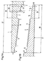
- Figure 1a is in a half-side longitudinal section an inventively trained Sleeve element 1 and in Figure 1b an inventively designed pin element. 2 shown.
- the sleeve member 1 has a between an inner shoulder 3 and a sleeve end face 4 lying conical internal threaded portion 5. Between the beginning of the female threaded portion 5 and the sleeve end face 4 is a conical thread-free section 6 is arranged.
- the second unthreaded portion 20 of the Sleeve element 1 is located between the end of the female threaded portion. 5 and the inner shoulder 3.
- the outer diameter of the sleeve member 1 is with an arrow 8 marked.
- the screwed to the sleeve element 1 has a between an outer Shoulder 9 and a spigot face 10 lying externally threaded portion 11. Between the end of the male threaded portion 11 and the outer shoulder. 9 there is a cylindrically shaped unthreaded section 12 and the second unthreaded portion 19 of the pin member 2 is located between the beginning the externally threaded portion 11 and the journal end surface 10.
- the second thread-free section 20 of the sleeve element 1 divided into a sealing part 26 and a groove 7 extending from the end of the Internal thread section 5 extends to the beginning of the sealing part 26.
- the sealing part 26 are two convex contoured contact surfaces 13, 14 are arranged.
- the inner shoulder 3 closer contact surface 13 is as a sealing seat and the farther away Contact surface 14 formed as a support contact.
- Sealing seat 13 and support contact 14 act when screwed together with a threaded section 19 of the Tenon element 2 arranged straight conical surface 15.
- the inclination of this Cone surface 15 is chosen steeply and is preferably at 1: 4.
- the flatter inclined In the direction Male threaded portion 11 merges into a second conical surface 16, the flatter inclined and preferably has a slope of 1: 6. Due to the Inclination difference serves the transition surface 16 as protection of the sealing seat before Damage.
- the inclination of the transition cone surface 16 preferably corresponds also the inclination of the female threaded portion 5 and the male threaded portion 11th
- the outer shoulder 9 of the pin member 2 forms the primary shoulder, the Kraftverschrauben is activated as the first. This is achieved by the distance 17 between the inner shoulder 3 and the sleeve end face is larger than that Distance 18 between the outer shoulder 9 and the pin end surface 10.
- a Another essential characteristic of the invention formed Pipe connection is that the length of the unthreaded portion 19 of the Tenon element 2 in the region of the inner joint is at least twice as large as the length of the unthreaded portion 6 of the sleeve member 1 in the region of External shock.
- the inner diameter of the pin element 2 is with an arrow 21st characterized.
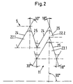
- FIG. 2 shows, on an enlarged scale, the design according to the invention Thread form shown.
- the upper part of Figure 2 shows a detail of 1 1 ⁇ 2 tooth 22.1, 22.2 of the female threaded portion 5 of the sleeve member 1.
- the lower part shows a detail of a tooth 23.1 of the male threaded portion 11 of Tenon element 2.
- the basic shape of both threaded sections 5, 11 is a coarse Round thread, based on API standard, which is advantageous for the necessary frequent screwing, which can be 100 times and more, and for the fast Threading, the so-called "Stabbing" of pin element 2 and sleeve element 1.
- Die Guide flank 24 has an angle of 30 ° analogous to the API rotary thread. Deviating from API, the angle of the load flank 25 is steeper in the range of 15 to 20 ° preferably of 18 °. This applies equally to the teeth 23.1 of Male thread portion 11 of the pin member second
Landscapes
- Engineering & Computer Science (AREA)
- Geology (AREA)
- Mechanical Engineering (AREA)
- General Engineering & Computer Science (AREA)
- Life Sciences & Earth Sciences (AREA)
- Mining & Mineral Resources (AREA)
- General Life Sciences & Earth Sciences (AREA)
- Fluid Mechanics (AREA)
- Environmental & Geological Engineering (AREA)
- Geochemistry & Mineralogy (AREA)
- Physics & Mathematics (AREA)
- Earth Drilling (AREA)
- Non-Disconnectible Joints And Screw-Threaded Joints (AREA)
- Cable Accessories (AREA)
- Laying Of Electric Cables Or Lines Outside (AREA)
- Mutual Connection Of Rods And Tubes (AREA)
- Joints With Pressure Members (AREA)
- Joints That Cut Off Fluids, And Hose Joints (AREA)
Description
- hohe Innendruckfestigkeit und Gasdichtheit,
- unempfindliche, robuste Ausführung für grobe Handhabung und vielfach wiederholte Anwendung desselben Werkzeuges,
- Vielfachverschraubung ohne Verlust der Dichtfunktion,
- Hohe Verschraubmomente und damit hohe Vorspannungen gegen Biegewechselbeanspruchung bzw. hohe Drehmomente für Workover-Arbeiten,
- leichter und schneller Ein- und Ausbau,
- leichte und kostengünstige Reparaturmöglichkeit.
- UD = Übermaß in der Dichtkontaktfläche
- σ 0,2 = Streckgrenze
- E = Elastizitätsmodul
- US = Übermaß in der Stützkontaktfläche
- LID = Abstand Innenschulter - Dichtsitz
- SL = mittlere Lippendicke
- LDS = Abstand Dichtsitz - Stützkontakt
- LSG = Abstand Stützkontakt - Gewindeeinlauf
- Fig. 1 a
- im halbseitigen Längsschnitt ein erfindungsgemäß ausgebildetes Muffenelement,
- Fig. 1b
- im halbseitigen Längsschnitt ein erfindungsgemäß ausgebildetes Zapfenelement und
- Fig. 2
- im vergrößeren Maßstab die erfindungsgemäß ausgebildete Gewindeform.
Claims (15)
- Rohrverbindung mit einem Zapfenelement, (2) das einen zwischen einer äußeren Schulter und einer Zapfenstimfläche (10) angeordneten kegeligen Außengewindeabschnitt und einen zwischen der äußeren Schulter und dem Außengewindeabschnitt sowie einen zwischen dem Außengewindeabschnitt und der Zapfenstirnfläche (10) angeordneten gewindefreien Abschnitt aufweist und mit einem mit dem Zapfenelement verschraubbaren Muffenelement, das ein zwischen einer inneren Schulter und einer Muffenstirnfläche (4) angeordneten kegeligen Innengewindeabschnitt und einen zwischen der äußeren Schulter und dem Innengewindeabschnitt sowie einen zwischen dem Innengewindeabschnitt und der Muffenstirnfläche (4) angeordneten gewindefreien Abschnitt aufweist, wobei die im verschraubten Zustand einander gegenüberliegenden gewindefreien Abschnitte des Zapfen- und Muffenelementes (1) im Bereich der inneren Schulter eine andere Länge aufweisen als die im Bereich der äußeren Schulter liegenden gewindefreien Abschnitte des Zapfen- und des Muffenelementes,
dadurch gekennzeichnet, daß die bei der Verschraubung mit der Muffenstirnfläche (4) in Kontakt tretende äußere Schulter (9) des Zapfenelementes (2) die Primärschulter bildet und der Abstand (18) zwischen Zapfenstirnfläche (10) und äußerer Schulter (9) geringer ist als der Abstand (17) zwischen Muffenstirnfläche (4) und innerer Schulter (3) des Muffenelementes (1)
daß die im Bereich der inneren Schulter (3) bzw. Zapfenstirnfläche (10) sich befindenden gewindefreien Abschnitte (19,20) mindestens zweimal so lang sind wie die im Bereich der äußeren Schulter (9) bzw. Muffenstirnfläche (4) sich befindenden gewindefreien Abschnitte (6,12), wobei der gewindefreie Abschnitt (20) des Muffenelementes (1) eine Nut (7) und ein Dichtteil (26) aufweist und im verschraubten Zustand der der Zapfenstimfläche (10) am nächsten liegende gewindefreie Bereich (15) des Zapfenelementes (2) mit dem Dichtteil (26) des Muffenelementes (1) in Kontakt tritt und eine metallische Dichtung bildet, wobei das Dichtteil (26) mit zwei axial voneinander beabstandeten Kontaktflächen (13,14) versehen ist, von denen die als Dichtsitz dienende Kontaktfläche (13) näher und die eine Stützwirkung ausübende zweite Kontaktfläche (14) weiter entfernt zur inneren Schulter (3) angeordnet sind und die zur Erhöhung der Elastizität angebrachte Nut (7) zwischen Gewindeabschnitt (5) und Dichtteil (26) angeordnet ist. - Rohrverbindung nach Anspruch 1,
dadurch gekennzeichent,
daß die im Bereich der inneren Schulter (3) bzw. Zapfenstimfläche (10) sich befindenden gewindefreien Abschnitte (19,20) dreimal so lang sind wie die im Bereich der äußeren Schulter (9) bzw. Muffenstimfläche (4) sich befindenden gewindefreien Abschnitte (6,12). - Rohrverbindung nach Anspruch 1 und 2,
dadurch gekennzeichnet, daß der Innen- (5) und der Außengewindeabschnitt (11) mit einem groben Standardgewinde versehen ist, dessen Lastflanke (25) einen Winkelbereich von 15 bis 20° und die Führungsflanke (24) einen Winkel von 30° aufweist. - Rohrverbindung nach Anspruch 3,
dadurch gekennzeichnet, daß die Lastflanke (25) einen Winkel von 18° aufweist. - Rohrverbindung nach Anspruch 3 und 4,
dadurch gekennzeichnet, daß die Gewindesteigung im Bereich zwischen 2,5-4 Gang/Zoll liegt. - Rohrverbindung nach Anspruch 5,
dadurch gekennzeichnet, daß die Gewindesteigung 3 Gang/Zoll beträgt. - Rohrverbindung nach einem der Ansprüche 3 - 6,
dadurch gekennzeichnet, daß der Kegel der Gewindeabschnitte (5,11) im Bereich zwischen 1:4 bis 1:8 liegt. - Rohrverbindung nach Anspruch 7,
dadurch gekennzeichnet, daß der Kegel der Gewindeabschnitte (5,11) 1 : 6 beträgt. - Rohrverbindung nach einem der Ansprüche 1 bis 8,
dadurch gekennzeichnet, daß das Zapfenelement (2) im gewindefreien Abschnitt (19) eine schräg verlaufende gerade Kontaktfläche und das Muffenelement (1) zwei damit zusammenwirkende konvex, ballig ausgebildete Kontaktflächen (13,14) aufweist. - Rohrverbindung nach Anspruch 9,
dadurch gekennzeichnet, daß die Radien der ballig ausgebildeten Kontaktflächen (13,14) im Muffenelement (1) größer als der mittlere Radius der Lippe des Zapfenelementes (2) sind und der Radius der Dichtkontaktfläche (13) stets kleiner ist als der der Stützkontaktfläche (14), und folgende Bedingengen erfüllt sind:RD = Radius der DichtkontaktflächeRL = mittlerer Radius der DichtlippeRS = Radius der Stützkontaktfläche - Rohrverbindung nach einem der Ansprüche 9 und 10,
dadurch gekennzeichnet, daß das Übermaß in den Kontaktflächen (13,14) (Durchmesserdifferenz Muffenelement(1)-Zapfenelement(2)) vom Werkstoff abhängig ist, wobei das Übermaß in der Stützkontaktfläche (14) stets kleiner ist als das der Dichtkontaktfläche (13), und folgende Bedingungen erfüllt sind:UD = Übermaß in der Dichtkontaktflächeσ 0,2 = StreckgrenzeE = ElastizitätsmodulUS = Übermaß in der Stützkontaktfläche - Rohrverbindung nach einem der Ansprüche 9 bis 11,
dadurch gekennzeichnet, daß die Abstände zwischen Dichtkontaktfläche (13) und Ende (10) des Zapfenelementes (2) einerseits und zwischen Dichtkontaktfläche (13) und Stützkontaktfläche (14) andererseits sowie zwischen Stützkontaktfläche (14) und Gewindeeinlauf (11) den folgenden Bedingungen genügentLID = Abstand Innenschulter - DichtsitzSL = mittlere LippendickeLDS = Abstand Dichtsitz - StützkontaktLSG = Abstand Stützkontakt - Gewindeeinlauf - Rohrverbindung nach einem der Ansprüche 7 bis 12,
dadurch gekennzeichnet, daß die Neigung des Kegels der geraden Kontaktfläche des Zapfenelementes (2) im Bereich zwischen 1:3 bis 1:5 liegt, die dann übergeht in eine dem Gewindeabschnitt (11) entsprechende Neigung. - Rohrverbindung nach Anspruch 13,
dadurch gekennzeichnet, daß die Neigung des Kegels der geraden Kontaktfläche des Zapfenelementes (2) 1:4 beträgt. - Rohrverbindung nach einem der Ansprüche 1 bis 14,
dadurch gekennzeichnet, daß die innere Schulter (3,10) als 90°-Schulter ausgebildet ist.
Applications Claiming Priority (3)
| Application Number | Priority Date | Filing Date | Title |
|---|---|---|---|
| DE19955377A DE19955377C2 (de) | 1999-11-10 | 1999-11-10 | Rohrverbindung |
| DE19955377 | 1999-11-10 | ||
| PCT/DE2000/003617 WO2001034936A1 (de) | 1999-11-10 | 2000-10-10 | Rohrverbindung |
Publications (2)
| Publication Number | Publication Date |
|---|---|
| EP1232322A1 EP1232322A1 (de) | 2002-08-21 |
| EP1232322B1 true EP1232322B1 (de) | 2003-06-25 |
Family
ID=7929402
Family Applications (1)
| Application Number | Title | Priority Date | Filing Date |
|---|---|---|---|
| EP00984830A Expired - Lifetime EP1232322B1 (de) | 1999-11-10 | 2000-10-10 | Rohrverbindung |
Country Status (12)
| Country | Link |
|---|---|
| US (1) | US6511102B2 (de) |
| EP (1) | EP1232322B1 (de) |
| JP (1) | JP5066316B2 (de) |
| AR (1) | AR026011A1 (de) |
| AT (1) | ATE243807T1 (de) |
| AU (1) | AU2148001A (de) |
| BR (1) | BR0015454A (de) |
| CA (1) | CA2389216C (de) |
| DE (2) | DE19955377C2 (de) |
| MX (1) | MXPA02002846A (de) |
| NO (1) | NO326307B1 (de) |
| WO (1) | WO2001034936A1 (de) |
Families Citing this family (43)
| Publication number | Priority date | Publication date | Assignee | Title |
|---|---|---|---|---|
| DE10150419A1 (de) * | 2001-10-11 | 2003-05-08 | Wolfgang Zimmermann | Abdichtung von Rohr- und Behälterverbindungen mittels Innendruck auf dünne Ränder |
| FR2833335B1 (fr) † | 2001-12-07 | 2007-05-18 | Vallourec Mannesmann Oil & Gas | Joint filete tubulaire superieur contenant au moins un element filete avec levre d'extremite |
| AU2002357111A1 (en) | 2001-12-07 | 2003-06-23 | Baker Hughes Incorporated | Modular thread connection with high fatigue resistance |
| ITRM20020234A1 (it) | 2002-04-30 | 2003-10-30 | Tenaris Connections Bv | Giunzione filettata per tubi. |
| ITRM20020274A1 (it) * | 2002-05-16 | 2003-11-17 | Tenaris Connections Bv | Giunzione filettata per tubi. |
| ITRM20020445A1 (it) * | 2002-09-06 | 2004-03-07 | Tenaris Connections Bv | Giunzione filettata per tubi. |
| US6832789B2 (en) * | 2002-11-01 | 2004-12-21 | Torquelock Corporation | Threaded pipe connection with cylindrical metal-to-metal, high pressure containment seal |
| GB0227603D0 (en) * | 2002-11-27 | 2002-12-31 | Hsc S A L | Improved casino joints |
| US20060006648A1 (en) * | 2003-03-06 | 2006-01-12 | Grimmett Harold M | Tubular goods with threaded integral joint connections |
| US8220842B2 (en) * | 2003-05-30 | 2012-07-17 | Vallourec Mannesmann Oil & Gas France | Threaded tubular connection which is resistant to bending stresses |
| FR2868146B1 (fr) * | 2004-03-26 | 2009-01-23 | Vallourec Mannesmann Oil Gas F | Joint filete tubulaire resistant aux contraintes de flexion |
| UA82694C2 (uk) * | 2003-06-06 | 2008-05-12 | Sumitomo Metal Ind | Нарізне з'єднання для сталевих труб |
| US7210710B2 (en) * | 2004-03-01 | 2007-05-01 | Omsco, Inc. | Drill stem connection |
| US7452007B2 (en) * | 2004-07-07 | 2008-11-18 | Weatherford/Lamb, Inc. | Hybrid threaded connection for expandable tubulars |
| RU2387912C2 (ru) * | 2004-12-06 | 2010-04-27 | ЭйчДжиДиЭс ИНК. | Трубное соединение |
| DK1861578T3 (da) * | 2005-03-02 | 2019-06-03 | Tuboscope Vetco France Sas | Borestangsforbindelse |
| SE530043C2 (sv) * | 2006-04-20 | 2008-02-12 | Sandvik Intellectual Property | Verktyg för spånavskiljande bearbetning samt del därtill |
| FR2913746B1 (fr) * | 2007-03-14 | 2011-06-24 | Vallourec Mannesmann Oil & Gas | Joint filete tubulaire etanche pour sollicitations de pression interieure et exterieure |
| JP5100755B2 (ja) * | 2007-10-03 | 2012-12-19 | 住友金属工業株式会社 | 鋼管用ねじ継手 |
| FR2925946B1 (fr) * | 2007-12-28 | 2009-12-11 | Vallourec Mannesmann Oil & Gas | Joint filete tubulaire etanche et resistant a des sollicitations successives de pressions |
| EP2337982B1 (de) * | 2008-10-20 | 2018-02-28 | Nippon Steel & Sumitomo Metal Corporation | Schraubverbindung für stahlrohre |
| US8678447B2 (en) * | 2009-06-04 | 2014-03-25 | National Oilwell Varco, L.P. | Drill pipe system |
| GB201005247D0 (en) * | 2010-03-29 | 2010-05-12 | Hsc Fzco | An improved seal between pipes |
| US20120001425A1 (en) * | 2010-07-02 | 2012-01-05 | Frank Ching King Lee | Fluid Line Connecting Fitting |
| GB201019413D0 (en) | 2010-11-17 | 2010-12-29 | Hsc Fzco | An improved seal between pipes |
| US9239122B2 (en) * | 2012-05-22 | 2016-01-19 | Single Buoy Moorings, Inc. | Pipe connection |
| US8894101B2 (en) * | 2012-09-07 | 2014-11-25 | Vetco Gray Inc. | Protected integral metal to metal seal |
| US9400069B2 (en) * | 2013-01-02 | 2016-07-26 | Frank's International, Llc | Threaded connector for larger diameter tubular members |
| MX367486B (es) * | 2013-01-28 | 2019-08-23 | Jfe Steel Corp | Junta roscada para tuberias de acero. |
| US9644771B1 (en) * | 2013-06-06 | 2017-05-09 | Bryan Lane | Threaded coupling |
| US10428594B2 (en) | 2013-11-22 | 2019-10-01 | Vetco Gray, LLC | Alignment guide feature for metal to metal seal protection on mechanical connections and couplings |
| US9598981B2 (en) * | 2013-11-22 | 2017-03-21 | Siemens Energy, Inc. | Industrial gas turbine exhaust system diffuser inlet lip |
| FR3027338B1 (fr) * | 2014-10-16 | 2016-12-02 | Vallourec Oil & Gas France | Connexion polyvalente etanche a double butee |
| US10041307B2 (en) | 2015-01-22 | 2018-08-07 | National Oilwell Varco, L.P. | Balanced thread form, tubulars employing the same, and methods relating thereto |
| US10006569B2 (en) | 2015-02-19 | 2018-06-26 | Arcelormittal Tubular Products Luxembourg S.A. | Threaded connection for pipes, such as oil and gas pipes |
| DE202015104842U1 (de) | 2015-09-11 | 2015-09-18 | Sysbohr Gmbh - Bohrtechnik Für Den Spezialtiefbau | Gewindeverbindung und Bohrgestänge mit Gewindeverbindung |
| US10116853B2 (en) * | 2015-11-11 | 2018-10-30 | Gopro, Inc. | Integrated sensor and lens assembly with differential threads adjustment |
| JP6912489B2 (ja) * | 2016-03-02 | 2021-08-04 | ドナルドソン カンパニー,インコーポレイティド | 液体フィルタ装置および方法 |
| EP3260649B1 (de) * | 2016-06-21 | 2019-12-18 | Energy Frontier Solutions S.L. | Gewindeverbindung für öl- und gasrohre |
| US20180252343A1 (en) | 2017-03-03 | 2018-09-06 | Arcelormittal Tubular Products Luxembourg S.A. | Torque shoulder of a premium connection |
| CN111456645B (zh) * | 2019-01-22 | 2022-05-10 | 中国石油天然气股份有限公司 | 连续油管连接器 |
| US12385326B2 (en) * | 2022-08-10 | 2025-08-12 | Saudi Arabian Oil Company | High torque threaded connections with external upset and multiple seals |
| US12644342B1 (en) * | 2025-04-03 | 2026-06-02 | Schlumberger Technology Corporation | Threaded coupling for well system |
Family Cites Families (13)
| Publication number | Priority date | Publication date | Assignee | Title |
|---|---|---|---|---|
| US2062407A (en) * | 1935-02-19 | 1936-12-01 | Spang Chalfant & Company Inc | Joint |
| US2532632A (en) * | 1948-10-04 | 1950-12-05 | Hydril Corp | Tubing and tubing joint |
| US3359013A (en) * | 1965-09-03 | 1967-12-19 | Hydril Co | Deep well casing jont |
| DE2438387C3 (de) * | 1974-08-07 | 1978-03-09 | Mannesmannroehren-Werke Ag, 4000 Duesseldorf | Gewindeverbindung für Ölfeldrohre |
| CA1182490A (en) * | 1981-12-17 | 1985-02-12 | Hughes Tool Company | Tool joint with internal/external make-up shoulder |
| GB2156933B (en) * | 1984-02-21 | 1988-01-13 | Vetco Offshore Ind Inc | Pipe connector |
| DE3660516D1 (en) * | 1986-01-23 | 1988-09-15 | Mannesmann Ag | Coupling for oil and gas field pipes |
| US5064224A (en) * | 1989-03-08 | 1991-11-12 | Baroid Technology, Inc. | Oil field tubular connection |
| US5505502A (en) * | 1993-06-09 | 1996-04-09 | Shell Oil Company | Multiple-seal underwater pipe-riser connector |
| US5492375A (en) * | 1994-07-21 | 1996-02-20 | Grant Tfw, Inc. | Drill pipe with improved connectors |
| DE4446806C1 (de) * | 1994-12-09 | 1996-05-30 | Mannesmann Ag | Gasdichte Rohrverbindung |
| JP3726302B2 (ja) * | 1995-03-15 | 2005-12-14 | 住友金属工業株式会社 | 油井管用ねじ継手 |
| DE19827821C1 (de) * | 1998-06-17 | 1999-11-25 | Mannesmann Ag | Bohrgestängeverbinder |
-
1999
- 1999-11-10 DE DE19955377A patent/DE19955377C2/de not_active Expired - Fee Related
-
2000
- 2000-10-10 BR BR0015454-7A patent/BR0015454A/pt not_active IP Right Cessation
- 2000-10-10 AT AT00984830T patent/ATE243807T1/de active
- 2000-10-10 WO PCT/DE2000/003617 patent/WO2001034936A1/de not_active Ceased
- 2000-10-10 CA CA002389216A patent/CA2389216C/en not_active Expired - Lifetime
- 2000-10-10 EP EP00984830A patent/EP1232322B1/de not_active Expired - Lifetime
- 2000-10-10 DE DE50002679T patent/DE50002679D1/de not_active Expired - Lifetime
- 2000-10-10 MX MXPA02002846A patent/MXPA02002846A/es active IP Right Grant
- 2000-10-10 AU AU21480/01A patent/AU2148001A/en not_active Abandoned
- 2000-10-10 JP JP2001536845A patent/JP5066316B2/ja not_active Expired - Fee Related
- 2000-10-11 AR ARP000105348A patent/AR026011A1/es active IP Right Grant
-
2001
- 2001-07-10 US US09/902,545 patent/US6511102B2/en not_active Expired - Lifetime
-
2002
- 2002-04-25 NO NO20021962A patent/NO326307B1/no not_active IP Right Cessation
Also Published As
| Publication number | Publication date |
|---|---|
| NO20021962D0 (no) | 2002-04-25 |
| WO2001034936A1 (de) | 2001-05-17 |
| JP5066316B2 (ja) | 2012-11-07 |
| DE19955377C2 (de) | 2002-05-02 |
| NO326307B1 (no) | 2008-11-03 |
| DE19955377A1 (de) | 2001-06-07 |
| ATE243807T1 (de) | 2003-07-15 |
| DE50002679D1 (de) | 2003-07-31 |
| JP2003514201A (ja) | 2003-04-15 |
| US20020017788A1 (en) | 2002-02-14 |
| NO20021962L (no) | 2002-04-25 |
| CA2389216C (en) | 2007-01-30 |
| US6511102B2 (en) | 2003-01-28 |
| EP1232322A1 (de) | 2002-08-21 |
| AR026011A1 (es) | 2002-12-26 |
| MXPA02002846A (es) | 2004-12-13 |
| AU2148001A (en) | 2001-06-06 |
| CA2389216A1 (en) | 2001-05-17 |
| BR0015454A (pt) | 2002-07-09 |
Similar Documents
| Publication | Publication Date | Title |
|---|---|---|
| DE19955377C2 (de) | Rohrverbindung | |
| DE3434763C2 (de) | Schraubkupplung für Ölfeldrohre | |
| EP0087557B1 (de) | Rohrverbindung für Metallrohre | |
| DE3131904C2 (de) | Hoch gasdichte Schraubverbindung für Öl- und Gasfeldrohre | |
| DE4446806C1 (de) | Gasdichte Rohrverbindung | |
| EP0229861B1 (de) | Rohrverbindung für Öl- und Gasfeldrohre | |
| DE4431377C1 (de) | Rohrverbinder | |
| DE19739458C2 (de) | Rohrverbinder | |
| EP0353182B1 (de) | Rohrgewindeverbindung | |
| DE69901515T2 (de) | Gewindeverbindung für zwei metallrohre | |
| DE69736232T2 (de) | Schraubverbindung für ölfeldrohre | |
| DE69912461T2 (de) | Metallrohrschraubverbindung mit hohem drehmoment | |
| DE69535474T2 (de) | Gewindeverbindung für Rohre | |
| DE60128687T2 (de) | Gewindeverbindiung mit verstärktem anschlag | |
| DE60318070T2 (de) | Rohranschlussstück mit gewinde | |
| DE102008047060B4 (de) | Gewindeverbindung | |
| DE60201518T2 (de) | Gewindeelement für eine ermüdungsbeständige gewinde-rohrverbindung | |
| DE3411519A1 (de) | Rohrverbindung | |
| DE2617667A1 (de) | Rohrverbindung | |
| EP0845092A1 (de) | Hochdruckverbindungssystem | |
| DE3431635C2 (de) | ||
| DE69910555T2 (de) | Zweistufige, keilförmige gewindeverbindung mit differentialdurchmesser | |
| DE3114651C2 (de) | Gasdichte Schraubverbindung für Öl- und Gas-Bohrlochrohre | |
| EP1117897B1 (de) | Bohrgestänge zum drehschlagbohren, insbesondere zum überlagerungsbohren | |
| EP1088150B1 (de) | Bohrgestängeverbinder |
Legal Events
| Date | Code | Title | Description |
|---|---|---|---|
| PUAI | Public reference made under article 153(3) epc to a published international application that has entered the european phase |
Free format text: ORIGINAL CODE: 0009012 |
|
| 17P | Request for examination filed |
Effective date: 20020510 |
|
| AK | Designated contracting states |
Kind code of ref document: A1 Designated state(s): AT BE CH CY DE DK ES FI FR GB GR IE IT LI LU MC NL PT SE |
|
| AX | Request for extension of the european patent |
Free format text: AL;LT;LV;MK;RO;SI |
|
| GRAH | Despatch of communication of intention to grant a patent |
Free format text: ORIGINAL CODE: EPIDOS IGRA |
|
| GRAH | Despatch of communication of intention to grant a patent |
Free format text: ORIGINAL CODE: EPIDOS IGRA |
|
| GRAH | Despatch of communication of intention to grant a patent |
Free format text: ORIGINAL CODE: EPIDOS IGRA |
|
| GRAA | (expected) grant |
Free format text: ORIGINAL CODE: 0009210 |
|
| AK | Designated contracting states |
Designated state(s): AT BE CH CY DE DK ES FI FR GB GR IE IT LI LU MC NL PT SE |
|
| PG25 | Lapsed in a contracting state [announced via postgrant information from national office to epo] |
Ref country code: IE Free format text: LAPSE BECAUSE OF FAILURE TO SUBMIT A TRANSLATION OF THE DESCRIPTION OR TO PAY THE FEE WITHIN THE PRESCRIBED TIME-LIMIT Effective date: 20030625 Ref country code: FI Free format text: LAPSE BECAUSE OF FAILURE TO SUBMIT A TRANSLATION OF THE DESCRIPTION OR TO PAY THE FEE WITHIN THE PRESCRIBED TIME-LIMIT Effective date: 20030625 Ref country code: NL Free format text: LAPSE BECAUSE OF FAILURE TO SUBMIT A TRANSLATION OF THE DESCRIPTION OR TO PAY THE FEE WITHIN THE PRESCRIBED TIME-LIMIT Effective date: 20030625 |
|
| REG | Reference to a national code |
Ref country code: GB Ref legal event code: FG4D Free format text: NOT ENGLISH |
|
| REG | Reference to a national code |
Ref country code: CH Ref legal event code: EP |
|
| GBT | Gb: translation of ep patent filed (gb section 77(6)(a)/1977) | ||
| REG | Reference to a national code |
Ref country code: IE Ref legal event code: FG4D Free format text: GERMAN |
|
| REF | Corresponds to: |
Ref document number: 50002679 Country of ref document: DE Date of ref document: 20030731 Kind code of ref document: P |
|
| PG25 | Lapsed in a contracting state [announced via postgrant information from national office to epo] |
Ref country code: DK Free format text: LAPSE BECAUSE OF FAILURE TO SUBMIT A TRANSLATION OF THE DESCRIPTION OR TO PAY THE FEE WITHIN THE PRESCRIBED TIME-LIMIT Effective date: 20030925 Ref country code: SE Free format text: LAPSE BECAUSE OF FAILURE TO SUBMIT A TRANSLATION OF THE DESCRIPTION OR TO PAY THE FEE WITHIN THE PRESCRIBED TIME-LIMIT Effective date: 20030925 Ref country code: PT Free format text: LAPSE BECAUSE OF FAILURE TO SUBMIT A TRANSLATION OF THE DESCRIPTION OR TO PAY THE FEE WITHIN THE PRESCRIBED TIME-LIMIT Effective date: 20030925 Ref country code: GR Free format text: LAPSE BECAUSE OF FAILURE TO SUBMIT A TRANSLATION OF THE DESCRIPTION OR TO PAY THE FEE WITHIN THE PRESCRIBED TIME-LIMIT Effective date: 20030925 |
|
| PG25 | Lapsed in a contracting state [announced via postgrant information from national office to epo] |
Ref country code: CY Free format text: LAPSE BECAUSE OF FAILURE TO SUBMIT A TRANSLATION OF THE DESCRIPTION OR TO PAY THE FEE WITHIN THE PRESCRIBED TIME-LIMIT Effective date: 20031010 Ref country code: LU Free format text: LAPSE BECAUSE OF NON-PAYMENT OF DUE FEES Effective date: 20031010 |
|
| PG25 | Lapsed in a contracting state [announced via postgrant information from national office to epo] |
Ref country code: BE Free format text: LAPSE BECAUSE OF NON-PAYMENT OF DUE FEES Effective date: 20031031 Ref country code: MC Free format text: LAPSE BECAUSE OF NON-PAYMENT OF DUE FEES Effective date: 20031031 |
|
| ET | Fr: translation filed | ||
| LTIE | Lt: invalidation of european patent or patent extension |
Effective date: 20030625 |
|
| NLV1 | Nl: lapsed or annulled due to failure to fulfill the requirements of art. 29p and 29m of the patents act | ||
| PG25 | Lapsed in a contracting state [announced via postgrant information from national office to epo] |
Ref country code: ES Free format text: LAPSE BECAUSE OF FAILURE TO SUBMIT A TRANSLATION OF THE DESCRIPTION OR TO PAY THE FEE WITHIN THE PRESCRIBED TIME-LIMIT Effective date: 20031222 |
|
| REG | Reference to a national code |
Ref country code: IE Ref legal event code: FD4D |
|
| BERE | Be: lapsed |
Owner name: *VALLOUREC MANNESMANN OIL & GAS GERMANY G.M.B.H. Effective date: 20031031 |
|
| PLBE | No opposition filed within time limit |
Free format text: ORIGINAL CODE: 0009261 |
|
| STAA | Information on the status of an ep patent application or granted ep patent |
Free format text: STATUS: NO OPPOSITION FILED WITHIN TIME LIMIT |
|
| 26N | No opposition filed |
Effective date: 20040326 |
|
| PG25 | Lapsed in a contracting state [announced via postgrant information from national office to epo] |
Ref country code: CH Free format text: LAPSE BECAUSE OF NON-PAYMENT OF DUE FEES Effective date: 20041031 Ref country code: LI Free format text: LAPSE BECAUSE OF NON-PAYMENT OF DUE FEES Effective date: 20041031 |
|
| REG | Reference to a national code |
Ref country code: CH Ref legal event code: PL |
|
| REG | Reference to a national code |
Ref country code: DE Ref legal event code: R082 Ref document number: 50002679 Country of ref document: DE Representative=s name: MEISSNER & MEISSNER, DE |
|
| REG | Reference to a national code |
Ref country code: GB Ref legal event code: 732E Free format text: REGISTERED BETWEEN 20110915 AND 20110921 |
|
| REG | Reference to a national code |
Ref country code: FR Ref legal event code: TP Owner name: V & M DEUTSCHLAND GMBH, DE Effective date: 20111007 |
|
| REG | Reference to a national code |
Ref country code: DE Ref legal event code: R082 Ref document number: 50002679 Country of ref document: DE Representative=s name: MEISSNER & MEISSNER, DE Effective date: 20111010 Ref country code: DE Ref legal event code: R081 Ref document number: 50002679 Country of ref document: DE Owner name: V & M DEUTSCHLAND GMBH, DE Free format text: FORMER OWNER: VALLOUREC MANNESMANN OIL & GAS GERMANY GMBH, 40472 DUESSELDORF, DE Effective date: 20111010 Ref country code: DE Ref legal event code: R082 Ref document number: 50002679 Country of ref document: DE Representative=s name: ANWALTSKANZLEI MEISSNER & MEISSNER, DE Effective date: 20111010 |
|
| REG | Reference to a national code |
Ref country code: FR Ref legal event code: CA Effective date: 20111130 |
|
| REG | Reference to a national code |
Ref country code: AT Ref legal event code: PC Ref document number: 243807 Country of ref document: AT Kind code of ref document: T Owner name: V&M DEUTSCHLAND GMBH, DE Effective date: 20120221 |
|
| REG | Reference to a national code |
Ref country code: FR Ref legal event code: PLFP Year of fee payment: 16 |
|
| REG | Reference to a national code |
Ref country code: FR Ref legal event code: PLFP Year of fee payment: 17 |
|
| REG | Reference to a national code |
Ref country code: FR Ref legal event code: PLFP Year of fee payment: 18 |
|
| REG | Reference to a national code |
Ref country code: FR Ref legal event code: PLFP Year of fee payment: 19 |
|
| PGFP | Annual fee paid to national office [announced via postgrant information from national office to epo] |
Ref country code: PL Payment date: 20181122 Year of fee payment: 11 |
|
| PGFP | Annual fee paid to national office [announced via postgrant information from national office to epo] |
Ref country code: FR Payment date: 20190913 Year of fee payment: 20 |
|
| PGFP | Annual fee paid to national office [announced via postgrant information from national office to epo] |
Ref country code: DE Payment date: 20190924 Year of fee payment: 20 |
|
| PGFP | Annual fee paid to national office [announced via postgrant information from national office to epo] |
Ref country code: IT Payment date: 20191009 Year of fee payment: 20 |
|
| PGFP | Annual fee paid to national office [announced via postgrant information from national office to epo] |
Ref country code: GB Payment date: 20191010 Year of fee payment: 20 |
|
| REG | Reference to a national code |
Ref country code: AT Ref legal event code: MM01 Ref document number: 243807 Country of ref document: AT Kind code of ref document: T Effective date: 20191010 |
|
| REG | Reference to a national code |
Ref country code: DE Ref legal event code: R071 Ref document number: 50002679 Country of ref document: DE |
|
| REG | Reference to a national code |
Ref country code: GB Ref legal event code: PE20 Expiry date: 20201009 |
|
| PG25 | Lapsed in a contracting state [announced via postgrant information from national office to epo] |
Ref country code: AT Free format text: LAPSE BECAUSE OF NON-PAYMENT OF DUE FEES Effective date: 20191010 |
|
| PG25 | Lapsed in a contracting state [announced via postgrant information from national office to epo] |
Ref country code: GB Free format text: LAPSE BECAUSE OF EXPIRATION OF PROTECTION Effective date: 20201009 |