EP1231703B1 - Unipolar machine - Google Patents
Unipolar machine Download PDFInfo
- Publication number
- EP1231703B1 EP1231703B1 EP02000570A EP02000570A EP1231703B1 EP 1231703 B1 EP1231703 B1 EP 1231703B1 EP 02000570 A EP02000570 A EP 02000570A EP 02000570 A EP02000570 A EP 02000570A EP 1231703 B1 EP1231703 B1 EP 1231703B1
- Authority
- EP
- European Patent Office
- Prior art keywords
- unipolar
- magnets
- magnet
- armature conductors
- conductors
- Prior art date
- Legal status (The legal status is an assumption and is not a legal conclusion. Google has not performed a legal analysis and makes no representation as to the accuracy of the status listed.)
- Expired - Lifetime
Links
Images
Classifications
-
- H—ELECTRICITY
- H02—GENERATION; CONVERSION OR DISTRIBUTION OF ELECTRIC POWER
- H02K—DYNAMO-ELECTRIC MACHINES
- H02K31/00—Acyclic motors or generators, i.e. DC machines having drum or disc armatures with continuous current collectors
Definitions
- the invention relates to a unipolar machine according to the preamble of claim 1.
- Electric machines typically generate currents of alternating polarity or varying voltage.
- AC voltages are generated, while in DC machines, the pulsating voltage is converted by means of commutators in a still pulsating DC voltage.
- Unipolar machines which use the principle of unipolar induction.
- unipolar induction a DC electrical voltage is generated by means of permanent magnets.
- the advantage of a unipolar machine lies in the fact that in the armature no periodically changing AC emf is induced, but an EMF of constant direction and constant height, so that a constant DC voltage is generated.
- a generator with a rotor which has a pair of fixedly connected unipolar magnets which rotate about their longitudinal axis, wherein in the cylindrical air gap between the two unipolar magnets Is arranged plurality of static armature conductors to which a consumer is connected, so that slip rings for electrically contacting the armature conductors are not necessary.
- CH 423 957 discloses a generator for generating direct current which has superconducting armature conductors.
- the armature conductors are not moved here, but are stationary. Electrical voltages are to be induced in the armature conductor by a rotating magnetic field supplied by three-phase energized coils.
- a permanent magnet motor which has two mechanically interconnected rotor and two stators.
- the stator windings are fed by a multi-pole three-phase current source and generate in the stators two sinusoidal DC fields in the same direction with the respective permanent magnet fluxes.
- a unipolar machine which uses a coaxially arranged unipolar magnet pair, wherein the outer magnet consists of magnetizable material.
- the outer magnet consists of magnetizable material.
- a series of stationary armature conductors are arranged, which are wound around the outer magnetizable material formed stator whose ends are connected to a power supply or a consumer.
- the inner permanent magnet is designed to rotate.
- the invention has for its object to provide an improved unipolar machine for the generation of direct current, which has no wearing parts such as slip rings, but nevertheless is suitable for high performance and has a particularly simple structure.
- the solution of the invention is based on a unipolar machine with a coaxially arranged unipolar magnet pair, in whose cylindrical air gap a series of stationary, parallel to the longitudinal axis of the unipolar magnet pair distributed on the circumference of the air gap extending armature conductors are arranged, whose ends to a Power supply or a consumer are connected.
- the solution according to the invention is characterized in that the outer unipolar magnet also has the same magnetic properties along its radial peripheral surface and is formed of magnetizable material, and that the armature conductors are connected in parallel at their respective ends via annular connections, each with a plurality of armature conductors as groups are connected in parallel and several groups are connected in series via guided on the outside of the unipolar magnet pair return conductor.
- the solution according to the invention is therefore based on the surprising finding that it is sufficient to drive only one of the two unipolar magnets and thus to move relative to the armature conductor in order to generate an electrical voltage. Previously, it was assumed that the two magnetic poles forming the magnetic field would have to be moved together.
- the unipolar machine according to the invention therefore has a new, but particularly simple construction, in which the inner unipolar magnet rotates while the outer unipolar magnet rests. So can be dispensed wear parts such as slip rings, which usually serve the electrical contacting rotating armature conductor.
- wear parts such as slip rings, which usually serve the electrical contacting rotating armature conductor.
- the rotating mass is reduced, so that fewer vibrations occur.
- Such a unipolar machine can be used particularly advantageously as a generator in wind turbines and as a hub drive in vehicles.
- the armature conductors are connected in parallel at their respective ends via annular connections, so that the individual armature conductors form a stable cylindrical body and at the same time are connected in parallel, so that high current intensities can be generated with the unipolar machine according to the invention.
- the armature conductors are connected in series via guided on the outside of the unipolar magnet pair return conductor, so that with the unipolar machine according to the invention, a high voltage can be generated.
- no compensating EMF is induced in the return conductor by the outer, stationary unipolar magnet, when the outer unipolar magnet rests and only the inner unipolar magnet rotates.
- armature conductors are connected in parallel as groups and a plurality of groups are connected in series, so that both the voltage and the current through the interconnection of the armature conductors can be arbitrarily increased.
- the armature conductors are coupled to the stationary unipolar magnet.
- the outer unipolar magnet with the armature conductors forms a unit when the inner unipolar magnet rotates.
- the armature conductors and the stationary unipolar magnet are cast together, so that the armature conductors are mechanically stabilized by the potting compound and are protected from damage.
- At least one of the unipolar machines is formed from annularly arranged bar magnets.
- unipolar magnets of arbitrary dimensions can be manufactured from known and simple bar magnets to be produced.
- a yoke element made of dynamo sheet which is the size of the running on the outer side of the outer magnet back air gap between the unipolar magnet pair reduced, wherein the yoke element has at least one opening for the passage of a shaft or electrical connection lines.
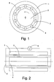
- the invention uses a unipolar magnet pair with an annular outer magnet 1 and an annular inner magnet 2, wherein the two magnets 1, 2 are formed unipolar, d. H. they have the same polarity magnetic properties along their radial peripheral surface.
- the outer magnet 1 is formed on its inner surface as a north pole and the inner magnet 2 on its outer surface as a south pole.
- Such unipolar magnets can be formed from known bar magnets by arranging a plurality of bar magnets with rectilinear pole orientation next to one another annularly, so that they cover the lateral surface of a cylindrical basic body.
- an air gap is formed, in which there is a row of annular conductors 3, 4, which are arranged along a connecting line 5.
- the outer unipolar magnet 1 is firmly connected to the conductors 3, 4, so that they form a unit.
- the conductors 3, 4 and the outer unipolar magnet 1 may be potted with a plastic so as to form a compact unit in which the outer unipolar magnet 1 and the conductors 3, 4 are protected by the potting compound.
- the outer unipolar magnet 1 and the conductors 3, 4 of the inner unipolar magnet 2 is inserted, which is rotatably mounted.
- the inner unipolar magnet 2 can, as already described, be formed from a plurality of bar magnets.
- the outer unipolar magnet 1 is a tube of a magnetizable material and the inner unipolar magnet 2 is preferably formed of bar magnets.
- Fig. 2 shows a side view of the basic structure of a unipolar machine according to the invention.
- the annular conductor 3 are arranged, which are coupled together at their ends via an annular connection 5, connected to a consumer 6.
- the armature conductors 3 are connected in parallel to each other and together with the outer unipolar magnets 1 form a cylindrical body into which the inner unipolar magnet 2 is inserted.
- the armature conductors 3 may also be connected in series, with the return conductors running along the outside of the unipolar machine, so as not to be guided by the magnetic field and cause a reverse EMF there.
- Another alternative is to connect several armature conductors in groups in parallel and the groups in series.
- a yoke element which is made of dynamo plate and the unipolar magnet pair 1, 2 interconnected to a narrow gap, which is necessary is, so that one of the two unipolar magnets 1, 2 can rotate.
- the yoke element has on both end sides of the unipolar machine according to the invention an opening through which a shaft for the inner unipolar magnet 2 and electrical lines for the connection of the conductors 3, 4 can be performed.
Landscapes
- Engineering & Computer Science (AREA)
- Power Engineering (AREA)
- Permanent Field Magnets Of Synchronous Machinery (AREA)
- Permanent Magnet Type Synchronous Machine (AREA)
- Fats And Perfumes (AREA)
- Control Of Motors That Do Not Use Commutators (AREA)
- Control Of Electric Motors In General (AREA)
- Dc Machiner (AREA)
- Dynamo-Electric Clutches, Dynamo-Electric Brakes (AREA)
Abstract
Description
Die Erfindung betrifft eine Unipolar-Maschine nach dem Oberbegriff des Anspruchs 1.The invention relates to a unipolar machine according to the preamble of
Elektrische Maschinen erzeugen üblicherweise Ströme mit wechselnder Polarität oder sich ändernder Spannung. Bei Drehstrom- oder Wechselstrommaschinen werden Wechselspannungen erzeugt, während bei Gleichstrommaschinen die pulsierende Spannung mittels Stromwendern in eine nach wie vor pulsierende Gleichspannung gewandelt wird.Electric machines typically generate currents of alternating polarity or varying voltage. In three-phase or AC machines AC voltages are generated, while in DC machines, the pulsating voltage is converted by means of commutators in a still pulsating DC voltage.
Es sind auch Unipolar-Maschinen bekannt, die das Prinzip einer Unipolar-Induktion verwenden. Bei der Unipolar-Induktion wird eine elektrische Gleichspannung mit Hilfe von Permanentmagneten erzeugt.Unipolar machines are also known which use the principle of unipolar induction. In unipolar induction, a DC electrical voltage is generated by means of permanent magnets.
Der Vorteil einer Unipolar-Maschine liegt also darin, dass in deren Anker keine sich periodisch ändernde Wechsel-EMK induziert wird, sondern eine EMK von gleichbleibender Richtung und gleichbleibender Höhe, so dass eine konstante Gleichspannung erzeugt wird.The advantage of a unipolar machine lies in the fact that in the armature no periodically changing AC emf is induced, but an EMF of constant direction and constant height, so that a constant DC voltage is generated.
Bisher bekannte Unipolar-Maschinen verwenden sich bewegende Ankerleiter, die stets in einem Feld gleicher Polarität angeordnet sind. Stromwender sind daher überflüssig, um eine Gleichspannung zu erzeugen. Die erzeugte EMK ist relativ gering, so dass die Ankerleiter in der Regel in Reihe geschaltet werden, indem man sie zwischen je zwei Bürsten legt und diese über Rückleiter, die außen um die Maschine herumzuführen sind, in Reihenschaltung miteinander verbindet. Aufgrund der doppelten Zahl von Bürsten gegenüber Gleichstrommaschinen haben sich Unipolar-Maschinen nicht durchgesetzt. Lediglich für Spezialanwendungen sind Unipolar-Maschinen, bei denen nur kleine Ströme erzeugt werden sollen, häufiger eingesetzt worden.Previously known unipolar machines use moving armature conductors, which are always arranged in a field of the same polarity. Current inverters are therefore superfluous to generate a DC voltage. The generated EMF is relatively low, so that the armature conductors are usually connected in series by placing them between two brushes and connecting them in series via return conductors to be guided around the outside of the machine. Due to the double number of brushes compared to DC machines unipolar machines have not prevailed. Only for special applications have unipolar machines, in which only small currents are to be generated, used more frequently.
Aus der DE 15 63 003 ist ein Generator mit einem Rotor bekannt, der ein Paar fest verbundener Unipolar-Magnete aufweist, die sich um ihre Längsachse drehen, wobei in dem zylinderförmigen Luftspalt zwischen den beiden Unipolar-Magneten eine Mehrzahl von ruhenden Ankerleitern angeordnet ist, an die ein Verbraucher angeschlossen ist, so dass Schleifringe zur elektrischen Kontaktierung der Ankerleiter nicht notwendig sind.From DE 15 63 003 a generator with a rotor is known which has a pair of fixedly connected unipolar magnets which rotate about their longitudinal axis, wherein in the cylindrical air gap between the two unipolar magnets Is arranged plurality of static armature conductors to which a consumer is connected, so that slip rings for electrically contacting the armature conductors are not necessary.
Die CH 423 957 hingegen offenbart einen Generator zur Erzeugung von Gleichstrom, der supraleitende Ankerleiter aufweist. Die Ankerleiter werden auch hier nicht bewegt, sondern sind ortsfest. Elektrische Spannungen sollen in dem Ankerleiter durch ein sich drehendes Magnetfeld induziert werden, das mit Drehstrom gespeiste Spulen liefern.On the other hand, CH 423 957 discloses a generator for generating direct current which has superconducting armature conductors. The armature conductors are not moved here, but are stationary. Electrical voltages are to be induced in the armature conductor by a rotating magnetic field supplied by three-phase energized coils.
Aus der US 4698538 ist ein bürstenloser elektrischer Motor mit Magneten bekannt, bei dem ein rohrförmiger innerer Magnet mit koaxialer Polverteilung verwendet wird. Die Magnetisierung erfolgt durch den magnetischen Fluss des inneren Magneten durch in einer radialen Ebene verlaufende ruhende Spulen, Stator und weitere den Magnetfluss bündelnde Teile. Die Feldverteilung ist nicht homogen.From US 4698538 a brushless electric motor with magnet is known, in which a tubular inner magnet with coaxial pole distribution is used. The magnetization is effected by the magnetic flux of the inner magnet by resting in a radial plane resting coil, stator and other magnetic flux bundling parts. The field distribution is not homogeneous.
In der DE 35 09 906 ist ein Dauermagnetmotor angegeben der zwei mechanisch miteinander verbundene Läufer und zwei Statoren aufweist. Die Statorwicklungen werden durch eine mehrpolige Drehstromquelle gespeiste und erzeugen in den Statoren zwei mit der jeweiligen Dauermagnetflüssen gleichsinnige sinusförmige Gleichstromfelder.In DE 35 09 906 a permanent magnet motor is provided which has two mechanically interconnected rotor and two stators. The stator windings are fed by a multi-pole three-phase current source and generate in the stators two sinusoidal DC fields in the same direction with the respective permanent magnet fluxes.
Aus der JP 58-99255 ist eine Unipolar-Maschinebekannt, die ein koaxial angeordnetes Unipolar-Magnetpaar verwendet, wobei der äußere Magnet aus magnetisierbarem Material besteht. Im zylinderförmigen Luftspalt zwischen den Magneten ist eine Reihe von ruhenden Ankerleitern angeordnet, die um den äußeren aus magnetisierbaren Material gebildeten Stator gewickelt sind, deren Enden an eine Stromversorgung bzw. einem Verbraucher angeschlossen sind. Der innere Permanentmagnet ist rotierend ausgebildet.From JP 58-99255 a unipolar machine is known, which uses a coaxially arranged unipolar magnet pair, wherein the outer magnet consists of magnetizable material. In the cylindrical air gap between the magnets, a series of stationary armature conductors are arranged, which are wound around the outer magnetizable material formed stator whose ends are connected to a power supply or a consumer. The inner permanent magnet is designed to rotate.
Der Erfindung liegt die Aufgabe zugrunde, eine verbesserte Unipolar-Maschine für die Erzeugung von Gleichstrom anzugeben, die keine Verschleißteile wie beispielsweise Schleifringe aufweist, aber gleichwohl für hohe Leistungen verwendbar ist und einen besonders einfachen Aufbau aufweist.The invention has for its object to provide an improved unipolar machine for the generation of direct current, which has no wearing parts such as slip rings, but nevertheless is suitable for high performance and has a particularly simple structure.
Diese Aufgabe wird durch die im Anspruch 1 angegebene Erfindung gelöst. Vorteilhafte Weiterbildungen der Erfindung sind in Unteransprüchen angegeben.This object is achieved by the invention defined in
Die Lösung der Erfindung geht aus von einer Unipolar-Maschine mit einem koaxial angeordneten Unipolar-Magnetpaar, in dessen zylinderförmigem Luftspalt eine Reihe von ruhenden, parallel zur Längsachse des Unipolar-Magnetpaars auf dem Umfang des Luftspalts verteilt verlaufende Ankerleiter angeordnet sind, deren Enden an eine Stromversorgung bzw. einen Verbraucher angeschlossen sind.The solution of the invention is based on a unipolar machine with a coaxially arranged unipolar magnet pair, in whose cylindrical air gap a series of stationary, parallel to the longitudinal axis of the unipolar magnet pair distributed on the circumference of the air gap extending armature conductors are arranged, whose ends to a Power supply or a consumer are connected.
Die erfindungsgemäße Lösung ist dadurch gekennzeichnet, dass der äußere Unipolar-Magnet ebenfalls entlang seiner radialen Umfangsfläche gleichpolige Magneteigenschaften aufweist und aus magnetisierbarem Material gebildet ist, und dass die Ankerleiter an ihren jeweiligen Enden über ringförmige Verbindungen miteinander parallel geschaltet sind, wobei jeweils mehrere Ankerleiter als Gruppen parallel geschaltet sind und mehrere Gruppen über an der Außenseite des Unipolar-Magnetpaars geführte Rückleiter in Reihe geschaltet sind.The solution according to the invention is characterized in that the outer unipolar magnet also has the same magnetic properties along its radial peripheral surface and is formed of magnetizable material, and that the armature conductors are connected in parallel at their respective ends via annular connections, each with a plurality of armature conductors as groups are connected in parallel and several groups are connected in series via guided on the outside of the unipolar magnet pair return conductor.
Die erfindungsgemäße Lösung beruht damit auf der überraschenden Erkenntnis, dass es ausreichend ist, nur einen der beiden Unipolar-Magneten anzutreiben und damit relativ zum Ankerleiter zu bewegen, um eine elektrische Spannung zu erzeugen. Bisher wurde angenommen, dass die beiden das Magnetfeld bildenden Magnetpole zusammen bewegt werden müssten.The solution according to the invention is therefore based on the surprising finding that it is sufficient to drive only one of the two unipolar magnets and thus to move relative to the armature conductor in order to generate an electrical voltage. Previously, it was assumed that the two magnetic poles forming the magnetic field would have to be moved together.
Die erfindungsgemäße Unipolar-Maschine weist daher einen neuen, aber besonders einfachen Aufbau auf, bei dem sich der innere Unipolar-Magnet dreht, während der äußere Unipolar-Magnet ruht. So kann auf Verschleißteile wie Schleifringe verzichtet werden, die üblicherweise der elektrischen Kontaktierung drehender Ankerleiter dienen. Außerdem ist bei der erfindungsgemäßen Unipolar-Maschine mit nur einem rotierenden Unipolar-Magneten die sich drehende Masse reduziert, so dass weniger Vibrationen auftreten. Eine derartige Unipolar-Maschine kann besonders vorteilhaft als Generator in Windkraftanlagen und als Nabenantrieb in Fahrzeugen verwendet werden.The unipolar machine according to the invention therefore has a new, but particularly simple construction, in which the inner unipolar magnet rotates while the outer unipolar magnet rests. So can be dispensed wear parts such as slip rings, which usually serve the electrical contacting rotating armature conductor. In addition, in the unipolar machine according to the invention with only one rotating unipolar magnet, the rotating mass is reduced, so that fewer vibrations occur. Such a unipolar machine can be used particularly advantageously as a generator in wind turbines and as a hub drive in vehicles.
Die Ankerleiter sind an ihren jeweiligen Enden über ringförmige Verbindungen miteinander parallel geschaltet, so dass die einzelnen Ankerleiter einen stabilen zylinderförmigen Körper bilden und gleichzeitig parallel geschaltet sind, damit mit der erfindungsgemäßen Unipolar-Maschine hohe Stromstärken erzeugt werden können.The armature conductors are connected in parallel at their respective ends via annular connections, so that the individual armature conductors form a stable cylindrical body and at the same time are connected in parallel, so that high current intensities can be generated with the unipolar machine according to the invention.
Es ist vorgesehen, dass die Ankerleiter über an der Außenseite des Unipolar-Magnetpaars geführte Rückleiter in Reihe geschaltet sind, so dass mit der erfindungsgemäßen Unipolar-Maschine eine hohe Spannung erzeugt werden kann. Dabei wird durch den äußeren, ruhenden Unipolar-Magneten keine kompensierende EMK in die Rückleiter induziert, wenn der äußere Unipolar-Magnet ruht und lediglich der innere Unipolar-Magnet sich dreht.It is envisaged that the armature conductors are connected in series via guided on the outside of the unipolar magnet pair return conductor, so that with the unipolar machine according to the invention, a high voltage can be generated. In this case, no compensating EMF is induced in the return conductor by the outer, stationary unipolar magnet, when the outer unipolar magnet rests and only the inner unipolar magnet rotates.
Dabei sind jeweils mehrere Ankerleiter als Gruppen parallel geschaltet und mehrere Gruppen sind in Reihe geschaltet, so dass sowohl die Spannung als auch die Stromstärke durch die Zusammenschaltung der Ankerleiter beliebig gesteigert werden können.In each case a plurality of armature conductors are connected in parallel as groups and a plurality of groups are connected in series, so that both the voltage and the current through the interconnection of the armature conductors can be arbitrarily increased.
In einer besonderen Ausführungsform ist vorgesehen, dass die Ankerleiter mit dem ruhenden Unipolar-Magneten gekoppelt sind. So bildet der äußere Unipolar-Magnet mit den Ankerleitern eine Einheit, wenn der innere Unipolar-Magnet sich dreht.In a particular embodiment, it is provided that the armature conductors are coupled to the stationary unipolar magnet. Thus, the outer unipolar magnet with the armature conductors forms a unit when the inner unipolar magnet rotates.
In einer weiteren Ausführungsform ist vorgesehen, dass die Ankerleiter und der ruhende Unipolar-Magnet zusammen vergossen sind, so dass die Ankerleiter durch die Vergussmasse mechanisch stabilisiert sind und vor Beschädigungen geschützt sind.In a further embodiment, it is provided that the armature conductors and the stationary unipolar magnet are cast together, so that the armature conductors are mechanically stabilized by the potting compound and are protected from damage.
In einer besonderen Ausführungsform ist vorgesehen, dass wenigstens einer der Unipolar-Maschinen aus ringförmig angeordneten Stabmagneten gebildet ist. Somit können Unipolar-Magnete mit beliebigen Abmessungen aus bekannten und einfachen herzustellenden Stabmagneten gefertigt werden.In a particular embodiment, it is provided that at least one of the unipolar machines is formed from annularly arranged bar magnets. Thus, unipolar magnets of arbitrary dimensions can be manufactured from known and simple bar magnets to be produced.
In einer weiteren Ausführungsform ist vorgesehen, dass ein Jochelement aus Dynamoblech vorgesehen ist, das die Größe des an der Außenseite des äußeren Magneten verlaufenden rückseitigen Luftspalts zwischen dem Unipolar-Magnetpaar reduziert, wobei das Jochelement wenigstens eine Öffnung für die Durchführung einer Welle oder elektrischer Anschlussleitungen aufweist. So können Verluste, hervorgerufen durch den rückseitigen Luftspalt zwischen dem ruhenden und rotierenden Unipolar-Magneten, deutlich reduziert werden.In a further embodiment it is provided that a yoke element made of dynamo sheet is provided, which is the size of the running on the outer side of the outer magnet back air gap between the unipolar magnet pair reduced, wherein the yoke element has at least one opening for the passage of a shaft or electrical connection lines. Thus, losses caused by the back air gap between the stationary and rotating unipolar magnets, can be significantly reduced.
Ein Ausführungsbeispiel wird nachstehend anhand der Zeichnungen näher erläutert. Es zeigen:
- Fig. 1
- eine Querschnittsansicht des prinzipiellen Aufbaus einer Unipolar-Maschine, und
- Fig. 2
- eine Seitenansicht eines prinzipiellen Aufbaus einer Unipolar-Maschine.
- Fig. 1
- a cross-sectional view of the basic structure of a unipolar machine, and
- Fig. 2
- a side view of a basic structure of a unipolar machine.
Es wird auf die Figuren 1 und 2 Bezug genommen.Reference is made to FIGS. 1 and 2.
Die Erfindung verwendet ein unipolares Magnetpaar mit einem ringförmigen Außenmagneten 1 und einem ringförmigen Innenmagneten 2, wobei die beiden Magnete 1, 2 unipolar ausgebildet sind, d. h. sie weisen entlang ihrer radialen Umfangsfläche gleichpolige Magneteigenschaften auf. Im gezeigten Beispiel der Fig. 1 ist der äußere Magnet 1 an seiner Innenfläche als Nordpol und der innere Magnet 2 an seiner Außenfläche als Südpol ausgebildet.The invention uses a unipolar magnet pair with an annular
Derartige Unipolar-Magnete können aus bekannten Stabmagneten gebildet werden, indem eine Mehrzahl von Stabmagneten mit gleichgerichteter Polorientierung nebeneinander liegend ringförmig angeordnet wird, so dass sie die Mantelfläche eines zylinderförmigen Grundkörpers bedecken.Such unipolar magnets can be formed from known bar magnets by arranging a plurality of bar magnets with rectilinear pole orientation next to one another annularly, so that they cover the lateral surface of a cylindrical basic body.
Zwischen den Unipolar-Magneten 1, 2 ist ein Luftspalt gebildet, in dem sich eine Reihe von ringförmigen Leitern 3, 4 befindet, die entlang einer Verbindungslinie 5 angeordnet sind. Dabei ist der äußere Unipolar-Magnet 1 fest mit den Leitern 3, 4 verbunden, so dass sie eine Einheit bilden. Die Leiter 3, 4 und der äußere Unipolar-Magnet 1 können mit einem Kunststoff vergossen sein, um so eine kompakte Einheit zu bilden, bei der der äußere Unipolar-Magnet 1 und die Leiter 3, 4 durch die Vergussmasse geschützt sind.Between the
In diese Einheit aus dem äußeren Unipolar-Magneten 1 und den Leitern 3, 4 ist der innere Unipolar-Magnet 2 eingesetzt, der drehbar gelagert ist. Der innere Unipolar-Magnet 2 kann, wie schon beschrieben, aus einer Mehrzahl von Stabmagneten gebildet sein. Gemäß der Erfindung ist der äußere Unipolar-Magnet 1 ein Rohr aus einem magnetisierbaren Material und der innere Unipolar-Magnet 2 ist vorzugsweise aus Stabmagneten gebildet.In this unit of the outer
Fig. 2 zeigt eine Seitenansicht des prinzipiellen Aufbaus einer Unipolar-Maschine nach der Erfindung. In dem Luftspalt zwischen den Magneten 1, 2 sind die ringförmigen Leiter 3 angeordnet, die an ihren Enden miteinander über eine ringförmige Verbindung 5 gekoppelt sind, an einen Verbraucher 6 angeschlossen. Dadurch sind die Ankerleiter 3 parallel miteinander verschaltet und bilden zusammen mit den äußeren Unipolar-Magneten 1 einen zylinderförmigen Körper, in den der innere Unipolar-Magnet 2 eingesetzt wird.Fig. 2 shows a side view of the basic structure of a unipolar machine according to the invention. In the air gap between the
Wenn es gewünscht ist, eine hohe Spannung zu erzielen, können die Ankerleiter 3 auch in Reihe miteinander geschaltet sein, wobei die Rückleiter entlang der Außenseite der Unipolar-Maschine verlaufen, um nicht durch das Magnetfeld geführt zu werden und dort eine umgekehrte EMK zu verursachen. Eine weitere Alternative besteht darin, mehrere Ankerleiter in Gruppen parallel und die Gruppen in Reihe zu schalten.If it is desired to achieve a high voltage, the
Um die Verluste in dem rückseitigen Luftspalt zwischen dem äußeren und dem inneren Unipolar-Magneten 1, 2 zu reduzieren, ist ein Jochelement vorgesehen, das aus Dynamoblech gefertigt ist und das Unipolar-Magnetpaar 1, 2 bis auf einen engen Spalt miteinander verbindet, der nötig ist, damit einer der beiden Unipolar-Magneten 1, 2 rotieren kann. Das Jochelement weist an beiden Stirnseiten der erfindungsgemäßen Unipolar-Maschine eine Öffnung auf, durch die eine Welle für den inneren Unipolar-Magneten 2 sowie elektrische Leitungen für den Anschluss der Leiter 3, 4 durchgeführt werden können.In order to reduce the losses in the rear air gap between the outer and inner
Claims (5)
- Unipolar machine with a pair of magnets, consisting of two coaxially arranged unipolar magnets (1, 2), in the cylindrical air gap of which a row of stationary armature conductors (3, 4), running parallel to the longitudinal axis of the pair of magnets divided over the periphery of the air gap, is arranged, the ends of said armature conductors being connected to a power supply or a consumer, wherein the inner unipolar magnet, constructed as a permanent magnet, has homopolar magnetic properties along its radial peripheral face and is constructed as rotating along a common longitudinal axis of the pair of magnets, and the outer unipolar magnet is constructed as stationary, characterised in that the outer unipolar magnet likewise has homopolar magnetic properties along its radial peripheral face and is made of magnetisable material, and in that the armature conductors are switched parallel to one another on their respective ends via annular connections (5), wherein in each case several armature conductors are switched parallel as groups and several groups are switched in series via return conductors guided on the outside of the pair of unipolar magnets (1, 2).
- Unipolar machine according to one of the previous claims, characterised in that the armature conductors (3, 4) are coupled to the stationary unipolar magnet (1) .
- Unipolar machine according to claim 2, characterised in that the armature conductors (3, 4) and the stationary unipolar magnet (1) are cast together.
- Unipolar machine according to one of the previous claims, characterised in that at least one of the unipolar magnets (1, 2) is made of annularly arranged bar magnets.
- Unipolar machine according to claim 1, characterised in that a yoke element made of dynamo sheet is provided, which reduces the size of the air gap running on the outside of the outer unipolar magnet between the pair of unipolar magnets (1, 2), the yoke element having at least one opening for the lead-through of a shaft and electrical connection lines.
Applications Claiming Priority (2)
| Application Number | Priority Date | Filing Date | Title |
|---|---|---|---|
| DE10101785 | 2001-01-17 | ||
| DE10101785A DE10101785B8 (en) | 2001-01-17 | 2001-01-17 | Unipolar machine |
Publications (3)
| Publication Number | Publication Date |
|---|---|
| EP1231703A2 EP1231703A2 (en) | 2002-08-14 |
| EP1231703A3 EP1231703A3 (en) | 2003-11-19 |
| EP1231703B1 true EP1231703B1 (en) | 2007-01-03 |
Family
ID=7670735
Family Applications (1)
| Application Number | Title | Priority Date | Filing Date |
|---|---|---|---|
| EP02000570A Expired - Lifetime EP1231703B1 (en) | 2001-01-17 | 2002-01-10 | Unipolar machine |
Country Status (4)
| Country | Link |
|---|---|
| EP (1) | EP1231703B1 (en) |
| AT (1) | ATE350803T1 (en) |
| DE (2) | DE10101785B8 (en) |
| ES (1) | ES2280438T3 (en) |
Cited By (1)
| Publication number | Priority date | Publication date | Assignee | Title |
|---|---|---|---|---|
| DE102009013660A1 (en) * | 2008-03-11 | 2009-12-10 | Schlüter, Gerd | Homopolar machine for use in e.g. wind turbine, has armature conductors that are parallelly connected as groups which are connected in row at external side of fixed magnetic ring and return conductor that is turned away from induction field |
Families Citing this family (3)
| Publication number | Priority date | Publication date | Assignee | Title |
|---|---|---|---|---|
| EP1742329A1 (en) * | 2005-07-08 | 2007-01-10 | Siemens Aktiengesellschaft | Stator of a turbo generator and turbo generator |
| DE102006060194B4 (en) * | 2006-12-20 | 2011-04-28 | Werth, Vladimir, Dipl.-Ing. | DC generator or motor |
| DE102016204667A1 (en) * | 2016-03-22 | 2017-09-28 | Bayerische Motoren Werke Aktiengesellschaft | Electric machine |
Citations (1)
| Publication number | Priority date | Publication date | Assignee | Title |
|---|---|---|---|---|
| JPS5899255A (en) * | 1981-12-09 | 1983-06-13 | Takashi Suzuki | Rotary electric machine |
Family Cites Families (8)
| Publication number | Priority date | Publication date | Assignee | Title |
|---|---|---|---|---|
| CH423957A (en) * | 1965-08-12 | 1966-11-15 | Bbc Brown Boveri & Cie | DC generator |
| DE1563003A1 (en) * | 1966-07-29 | 1970-01-15 | Soltau Dietrich Carsten | New generator for generating direct and alternating current |
| FR1586421A (en) * | 1968-08-07 | 1970-02-20 | ||
| DE2823313A1 (en) * | 1978-05-29 | 1979-12-06 | Siemens Ag | Homopolar single or polyphase AC generator - has radially magnetised permanent magnets between lamination packs and casing |
| DE3509906A1 (en) * | 1984-10-15 | 1986-04-17 | M. Fahrettin Dipl.-Ing. Kadiköy-Istanbul Ergüvenc | Permanent-magnet motor |
| JPS61280752A (en) * | 1985-06-05 | 1986-12-11 | Oopack Kk | Brushless dc rotary electric machine |
| JPH01270759A (en) * | 1988-04-11 | 1989-10-30 | Daigen Kin | Multiphase symmetrical unipole commutatorless dc motor |
| JPH0993996A (en) * | 1995-09-28 | 1997-04-04 | Yoshiaki Takahashi | Generator motor |
-
2001
- 2001-01-17 DE DE10101785A patent/DE10101785B8/en not_active Expired - Fee Related
-
2002
- 2002-01-10 DE DE50209116T patent/DE50209116D1/en not_active Expired - Lifetime
- 2002-01-10 ES ES02000570T patent/ES2280438T3/en not_active Expired - Lifetime
- 2002-01-10 AT AT02000570T patent/ATE350803T1/en not_active IP Right Cessation
- 2002-01-10 EP EP02000570A patent/EP1231703B1/en not_active Expired - Lifetime
Patent Citations (1)
| Publication number | Priority date | Publication date | Assignee | Title |
|---|---|---|---|---|
| JPS5899255A (en) * | 1981-12-09 | 1983-06-13 | Takashi Suzuki | Rotary electric machine |
Cited By (1)
| Publication number | Priority date | Publication date | Assignee | Title |
|---|---|---|---|---|
| DE102009013660A1 (en) * | 2008-03-11 | 2009-12-10 | Schlüter, Gerd | Homopolar machine for use in e.g. wind turbine, has armature conductors that are parallelly connected as groups which are connected in row at external side of fixed magnetic ring and return conductor that is turned away from induction field |
Also Published As
| Publication number | Publication date |
|---|---|
| EP1231703A3 (en) | 2003-11-19 |
| DE50209116D1 (en) | 2007-02-15 |
| DE10101785B8 (en) | 2004-08-05 |
| ATE350803T1 (en) | 2007-01-15 |
| DE10101785B4 (en) | 2004-04-29 |
| DE10101785A1 (en) | 2002-07-25 |
| ES2280438T3 (en) | 2007-09-16 |
| EP1231703A2 (en) | 2002-08-14 |
Similar Documents
| Publication | Publication Date | Title |
|---|---|---|
| DE69309444T2 (en) | BRUSHLESS DC MOTOR / GENERATOR | |
| DE69504391T2 (en) | Flow-controlled, permanent magnetic, dynamoelectric machine | |
| EP0454183B1 (en) | Rotary electric motor | |
| EP2639936B1 (en) | Electrical machine with permanently excited rotor and permanently excited rotor | |
| DE2225442A1 (en) | COLLECTORLESS DC MOTOR | |
| WO2010102987A1 (en) | Rotating transformer for supplying the field winding in a dynamoelectric machine | |
| EP1657802A1 (en) | Revolving-field electric machine and its primary | |
| DE69915604T2 (en) | IMPROVED ELECTRIC MOTOR | |
| DE1230486B (en) | Electric machine which is provided with two magnets arranged on both sides of the rotor | |
| EP0394528B1 (en) | Synchronous machine | |
| EP3555998B1 (en) | Rotor and rotor circuit for an electrical motor | |
| DE3933790C2 (en) | Electrical machine with a rotor and a stator | |
| WO2013023819A2 (en) | Electrical machine | |
| EP0150070A2 (en) | Commutatorless direct-current motor with a ironless stator winding | |
| DE69214700T2 (en) | Superconducting brushless homopolar motor with a rotor with several turns | |
| DE4027041A1 (en) | ELECTRIC GENERATOR | |
| EP1231703B1 (en) | Unipolar machine | |
| DE102012103731A1 (en) | electric motor | |
| DE102012102946A1 (en) | electric motor | |
| DE69929709T2 (en) | ELECTRICAL MACHINE WITH PERMANENT MAGNETS AND ENERGY SAVING CONTROL | |
| DE2914185A1 (en) | GENERATOR WITH PERMANENT MAGNET | |
| DE69019315T2 (en) | SYNCHRONOUS MACHINE. | |
| DE1488053B2 (en) | ROTATING ELECTRIC DC MACHINE FOR LOW VOLTAGES AND LARGE CURRENTS | |
| DE8905353U1 (en) | Synchronous machine | |
| EP2149963B1 (en) | Magnet spin motor |
Legal Events
| Date | Code | Title | Description |
|---|---|---|---|
| PUAI | Public reference made under article 153(3) epc to a published international application that has entered the european phase |
Free format text: ORIGINAL CODE: 0009012 |
|
| AK | Designated contracting states |
Kind code of ref document: A2 Designated state(s): AT BE CH CY DE DK ES FI FR GB GR IE IT LI LU MC NL PT SE TR |
|
| AX | Request for extension of the european patent |
Free format text: AL;LT;LV;MK;RO;SI |
|
| PUAL | Search report despatched |
Free format text: ORIGINAL CODE: 0009013 |
|
| AK | Designated contracting states |
Kind code of ref document: A3 Designated state(s): AT BE CH CY DE DK ES FI FR GB GR IE IT LI LU MC NL PT SE TR |
|
| AX | Request for extension of the european patent |
Extension state: AL LT LV MK RO SI |
|
| RIC1 | Information provided on ipc code assigned before grant |
Ipc: 7H 02K 31/00 A Ipc: 7H 02K 53/00 B |
|
| RIN1 | Information on inventor provided before grant (corrected) |
Inventor name: LIPSKI, HANS-JUERGEN |
|
| 17P | Request for examination filed |
Effective date: 20040514 |
|
| AKX | Designation fees paid |
Designated state(s): AT BE CH CY DE DK ES FI FR GB GR IE IT LI LU MC NL PT SE TR |
|
| 17Q | First examination report despatched |
Effective date: 20040706 |
|
| GRAP | Despatch of communication of intention to grant a patent |
Free format text: ORIGINAL CODE: EPIDOSNIGR1 |
|
| GRAS | Grant fee paid |
Free format text: ORIGINAL CODE: EPIDOSNIGR3 |
|
| GRAA | (expected) grant |
Free format text: ORIGINAL CODE: 0009210 |
|
| AK | Designated contracting states |
Kind code of ref document: B1 Designated state(s): AT BE CH CY DE DK ES FI FR GB GR IE IT LI LU MC NL PT SE TR |
|
| PG25 | Lapsed in a contracting state [announced via postgrant information from national office to epo] |
Ref country code: NL Free format text: LAPSE BECAUSE OF FAILURE TO SUBMIT A TRANSLATION OF THE DESCRIPTION OR TO PAY THE FEE WITHIN THE PRESCRIBED TIME-LIMIT Effective date: 20070103 Ref country code: DK Free format text: LAPSE BECAUSE OF FAILURE TO SUBMIT A TRANSLATION OF THE DESCRIPTION OR TO PAY THE FEE WITHIN THE PRESCRIBED TIME-LIMIT Effective date: 20070103 Ref country code: FI Free format text: LAPSE BECAUSE OF FAILURE TO SUBMIT A TRANSLATION OF THE DESCRIPTION OR TO PAY THE FEE WITHIN THE PRESCRIBED TIME-LIMIT Effective date: 20070103 Ref country code: IE Free format text: LAPSE BECAUSE OF FAILURE TO SUBMIT A TRANSLATION OF THE DESCRIPTION OR TO PAY THE FEE WITHIN THE PRESCRIBED TIME-LIMIT Effective date: 20070103 |
|
| REG | Reference to a national code |
Ref country code: GB Ref legal event code: FG4D Free format text: NOT ENGLISH |
|
| PG25 | Lapsed in a contracting state [announced via postgrant information from national office to epo] |
Ref country code: LI Free format text: LAPSE BECAUSE OF NON-PAYMENT OF DUE FEES Effective date: 20070131 Ref country code: CH Free format text: LAPSE BECAUSE OF NON-PAYMENT OF DUE FEES Effective date: 20070131 Ref country code: MC Free format text: LAPSE BECAUSE OF NON-PAYMENT OF DUE FEES Effective date: 20070131 |
|
| REF | Corresponds to: |
Ref document number: 50209116 Country of ref document: DE Date of ref document: 20070215 Kind code of ref document: P |
|
| REG | Reference to a national code |
Ref country code: IE Ref legal event code: FG4D Free format text: LANGUAGE OF EP DOCUMENT: GERMAN |
|
| PG25 | Lapsed in a contracting state [announced via postgrant information from national office to epo] |
Ref country code: SE Free format text: LAPSE BECAUSE OF FAILURE TO SUBMIT A TRANSLATION OF THE DESCRIPTION OR TO PAY THE FEE WITHIN THE PRESCRIBED TIME-LIMIT Effective date: 20070403 |
|
| GBT | Gb: translation of ep patent filed (gb section 77(6)(a)/1977) |
Effective date: 20070404 |
|
| PG25 | Lapsed in a contracting state [announced via postgrant information from national office to epo] |
Ref country code: PT Free format text: LAPSE BECAUSE OF FAILURE TO SUBMIT A TRANSLATION OF THE DESCRIPTION OR TO PAY THE FEE WITHIN THE PRESCRIBED TIME-LIMIT Effective date: 20070604 |
|
| NLV1 | Nl: lapsed or annulled due to failure to fulfill the requirements of art. 29p and 29m of the patents act | ||
| ET | Fr: translation filed | ||
| REG | Reference to a national code |
Ref country code: IE Ref legal event code: FD4D |
|
| REG | Reference to a national code |
Ref country code: CH Ref legal event code: PL |
|
| REG | Reference to a national code |
Ref country code: ES Ref legal event code: FG2A Ref document number: 2280438 Country of ref document: ES Kind code of ref document: T3 |
|
| PLBE | No opposition filed within time limit |
Free format text: ORIGINAL CODE: 0009261 |
|
| STAA | Information on the status of an ep patent application or granted ep patent |
Free format text: STATUS: NO OPPOSITION FILED WITHIN TIME LIMIT |
|
| 26N | No opposition filed |
Effective date: 20071005 |
|
| BERE | Be: lapsed |
Owner name: LIPSKI, HANS-JURGEN Effective date: 20070131 Owner name: SCHLUTER, GERD Effective date: 20070131 |
|
| PG25 | Lapsed in a contracting state [announced via postgrant information from national office to epo] |
Ref country code: BE Free format text: LAPSE BECAUSE OF NON-PAYMENT OF DUE FEES Effective date: 20070131 |
|
| PG25 | Lapsed in a contracting state [announced via postgrant information from national office to epo] |
Ref country code: GR Free format text: LAPSE BECAUSE OF FAILURE TO SUBMIT A TRANSLATION OF THE DESCRIPTION OR TO PAY THE FEE WITHIN THE PRESCRIBED TIME-LIMIT Effective date: 20070404 |
|
| PG25 | Lapsed in a contracting state [announced via postgrant information from national office to epo] |
Ref country code: AT Free format text: LAPSE BECAUSE OF NON-PAYMENT OF DUE FEES Effective date: 20070110 |
|
| PGFP | Annual fee paid to national office [announced via postgrant information from national office to epo] |
Ref country code: TR Payment date: 20080109 Year of fee payment: 7 |
|
| PG25 | Lapsed in a contracting state [announced via postgrant information from national office to epo] |
Ref country code: CY Free format text: LAPSE BECAUSE OF FAILURE TO SUBMIT A TRANSLATION OF THE DESCRIPTION OR TO PAY THE FEE WITHIN THE PRESCRIBED TIME-LIMIT Effective date: 20070103 |
|
| PG25 | Lapsed in a contracting state [announced via postgrant information from national office to epo] |
Ref country code: LU Free format text: LAPSE BECAUSE OF NON-PAYMENT OF DUE FEES Effective date: 20070110 |
|
| PGFP | Annual fee paid to national office [announced via postgrant information from national office to epo] |
Ref country code: FR Payment date: 20110317 Year of fee payment: 10 Ref country code: IT Payment date: 20110228 Year of fee payment: 10 |
|
| PGFP | Annual fee paid to national office [announced via postgrant information from national office to epo] |
Ref country code: GB Payment date: 20110228 Year of fee payment: 10 Ref country code: ES Payment date: 20110228 Year of fee payment: 10 |
|
| GBPC | Gb: european patent ceased through non-payment of renewal fee |
Effective date: 20120110 |
|
| REG | Reference to a national code |
Ref country code: FR Ref legal event code: ST Effective date: 20120928 |
|
| PG25 | Lapsed in a contracting state [announced via postgrant information from national office to epo] |
Ref country code: GB Free format text: LAPSE BECAUSE OF NON-PAYMENT OF DUE FEES Effective date: 20120110 |
|
| PG25 | Lapsed in a contracting state [announced via postgrant information from national office to epo] |
Ref country code: IT Free format text: LAPSE BECAUSE OF NON-PAYMENT OF DUE FEES Effective date: 20120110 |
|
| PG25 | Lapsed in a contracting state [announced via postgrant information from national office to epo] |
Ref country code: FR Free format text: LAPSE BECAUSE OF NON-PAYMENT OF DUE FEES Effective date: 20120131 |
|
| PG25 | Lapsed in a contracting state [announced via postgrant information from national office to epo] |
Ref country code: TR Free format text: LAPSE BECAUSE OF NON-PAYMENT OF DUE FEES Effective date: 20090110 |
|
| PGFP | Annual fee paid to national office [announced via postgrant information from national office to epo] |
Ref country code: DE Payment date: 20130227 Year of fee payment: 12 |
|
| REG | Reference to a national code |
Ref country code: ES Ref legal event code: FD2A Effective date: 20130705 |
|
| PG25 | Lapsed in a contracting state [announced via postgrant information from national office to epo] |
Ref country code: ES Free format text: LAPSE BECAUSE OF NON-PAYMENT OF DUE FEES Effective date: 20120111 |
|
| REG | Reference to a national code |
Ref country code: DE Ref legal event code: R119 Ref document number: 50209116 Country of ref document: DE |
|
| PG25 | Lapsed in a contracting state [announced via postgrant information from national office to epo] |
Ref country code: DE Free format text: LAPSE BECAUSE OF NON-PAYMENT OF DUE FEES Effective date: 20140801 |
|
| REG | Reference to a national code |
Ref country code: DE Ref legal event code: R119 Ref document number: 50209116 Country of ref document: DE Effective date: 20140801 |