EP1231453A2 - Berührungslose Füllstandsmessvorrichtung - Google Patents
Berührungslose Füllstandsmessvorrichtung Download PDFInfo
- Publication number
- EP1231453A2 EP1231453A2 EP02001186A EP02001186A EP1231453A2 EP 1231453 A2 EP1231453 A2 EP 1231453A2 EP 02001186 A EP02001186 A EP 02001186A EP 02001186 A EP02001186 A EP 02001186A EP 1231453 A2 EP1231453 A2 EP 1231453A2
- Authority
- EP
- European Patent Office
- Prior art keywords
- predetermined
- signal
- container
- evaluation device
- echo
- Prior art date
- Legal status (The legal status is an assumption and is not a legal conclusion. Google has not performed a legal analysis and makes no representation as to the accuracy of the status listed.)
- Granted
Links
Images

Classifications
-
- G—PHYSICS
- G01—MEASURING; TESTING
- G01F—MEASURING VOLUME, VOLUME FLOW, MASS FLOW OR LIQUID LEVEL; METERING BY VOLUME
- G01F23/00—Indicating or measuring liquid level or level of fluent solid material, e.g. indicating in terms of volume or indicating by means of an alarm
- G01F23/22—Indicating or measuring liquid level or level of fluent solid material, e.g. indicating in terms of volume or indicating by means of an alarm by measuring physical variables, other than linear dimensions, pressure or weight, dependent on the level to be measured, e.g. by difference of heat transfer of steam or water
- G01F23/28—Indicating or measuring liquid level or level of fluent solid material, e.g. indicating in terms of volume or indicating by means of an alarm by measuring physical variables, other than linear dimensions, pressure or weight, dependent on the level to be measured, e.g. by difference of heat transfer of steam or water by measuring the variations of parameters of electromagnetic or acoustic waves applied directly to the liquid or fluent solid material
- G01F23/284—Electromagnetic waves
Definitions
- the invention relates generally to a method for the contactless determination of a Overfilling a container filled with a filling material, from which on one An envelope curve is generated. Furthermore, the Invention an evaluation device for performing such a method and a Level measuring device that is equipped with such an evaluation device. Level measuring devices of the type of interest here work in particular according to the so-called pulse echo principle and sample a reflected echo signal.
- Level measuring devices or sensors which are measured by measuring individual echoes in one Envelope to determine the level is known. So the envelope becomes more special For example, with low-pass filters, in particular a pull-down low-pass filter examined. In this way, the echoes are searched for in areas that had previously been through an intersection Detection threshold with the echo signal were set. So there is an echo in the Envelope from various features, such as amplitude, echo width at a certain amplitude below the maximum and slope of the sampled echo signal before the maximum. In this way, the actual useful echo, i.e. H. the echo that of the actual product surface was reflected, determined, in particular separately from the other echoes and the decaying transmission signal.
- EP 0 871 019 A1 describes a method for determining an overfill in the Measurement of a fill level using an ultrasonic transducer is known. With this procedure Overfilling is detected when the ultrasonic transducer in the filling, here one Liquid that is immersed or covered by it. To determine the overcrowding, the by the oscillation of the ultrasound transducer after the end of each ultrasound transmission pulse generated decaying output signal of the ultrasonic transducer evaluated. This takes advantage of the fact that the ringing period is due to the better Coupling the ultrasonic transducer to the liquid than in air is shorter if the Ultrasonic transducer is covered by the liquid.
- the ringing amplitude of the output signal of the Ultrasonic transducer at a predetermined time after the end of the AC pulse compared with a predetermined threshold, the so is dimensioned so that it falls below when the ultrasonic transducer from the liquid is covered.
- the ringing amplitude of the Output signal of the ultrasonic transducer in a predetermined time window after the end of the AC voltage pulse is integrated and the integration value with a predetermined threshold value is compared, which is dimensioned so that it falls below when the ultrasonic transducer is covered with liquid.
- DE 195 38 678 A1 A similar arrangement can be seen from DE 195 38 678 A1.
- DE 198 17 378 A1 which is generally a Level measuring device disclosed, compared to known float switches the level of a material is less sensitive and easier to maintain Reflection signals of electromagnetic radiation is detected, in particular here represents so-called TDR level measuring device.
- the technical problem underlying the invention is a method for Provide detection of an overfill of a container filled with a filling material. It In particular, a possibility is to be created that a particularly after Impulse echo principle working and level sensor scanning a reflected echo signal can automatically detect overfilling of a container.
- the invention is based on the idea that occurs in the close range of the echo signal use large signal amplitudes to determine congestion. So will an envelope curve according to the invention from echo signals reflected on a product surface generated.
- the echo signal amplitude is in a predetermined close range of the envelope prepared mathematically and compared with a predetermined comparison value. at If the predetermined comparison value is exceeded, the container is overfilled representing signal output.
- the echo signal amplitude is in the predetermined Close range is integrated.
- the transmission signal is a radar pulse from a radar sensor
- the predetermined close range depending on the transmission signal frequency set.
- the signals to be evaluated are ultrasonic signals, it is from Advantage, the predetermined close range depending on the structure of the sound transducer for transmitting and receiving ultrasonic pulses and the transmission frequency.
- the close range it is expedient to define the close range so that it is from the beginning of the Envelope extends to the point on the envelope at which the amplitude value around a predetermined safety margin is higher than the system noise. So can for example the general system noise at a transmission frequency of 24 GHz at about 20dB. If you now choose a safety distance of 10dB, for example, then it extends the close range from the beginning of the envelope to the point at which the Amplitude value is again 30dB. In the above example, that would be too close-up area to be examined thus approximately 1 m.
- the output of a signal representing an overfill of the container is fundamental only makes sense if the safe area for measuring the fill level is left. Accordingly, it is particularly expedient to include the removal of a useful echo compare a predetermined distance value, and only in the event that the Distance of the useful echo is smaller than the predetermined distance value, the Output signal representing overfill of the container.
- the signal-to-noise ratio can also be expedient in addition or as an individual query with a predetermined signal-to-noise ratio, and only for the case that the signal-to-noise ratio is smaller than the predetermined signal-to-noise ratio value, output a signal representing the overfilling of the container. That is the term signal-to-noise ratio, also called measurement certainty Amplitude of the level echo above the system noise or the decaying transmission signal to understand.
- this processing unit is designed such that one or more features of the aforementioned method according to the invention can thus be carried out.
- an evaluation device can be used as an independent unit be formed, which is physically separated from the actual level measuring device. So it would be conceivable, for example, to include such an evaluation device in a control center integrate. Depending on the circumstances, it is also extremely advantageous to use one Integrate evaluation device directly in the level measuring device. In this case the evaluation device forms part of the level measuring device. About a known one Communication line is then to other facilities such. B. a control center that Signal of an overfill is output, or if there is no overfill, a Level representative signal.
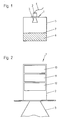
- a Level meter 1 is mounted in the ceiling area of a container 5.
- a filling material 6 bulk material or liquid, which forms a filling material surface 7.
- the level measuring device 1 mounted in the container 5 comprises a housing 2 and a Horn antenna 3. It is via a cable 4, in particular a so-called 4-20 mA two-wire loop, to a power supply and communication device, not shown here connected.
- the level measuring device 1 is included an evaluation device 10, a transmitter device 11 and a receiver device 12 shown.
- the transmitter 11 generates short radar pulses in the microwave range transmitted via the horn antenna 3 in the direction of the product surface 7. At the Filling surface 7, these signals are reflected and via the same antenna 3 receive.
- the receiver device 12 these are in accordance with the prior art processed further and evaluated in the evaluation device 10. This is known in Generated an envelope from the individual echo signals. This envelope will then again examined in more detail by means of mathematical methods, in particular as described in the following flowcharts is illustrated.
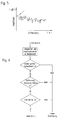
- FIG. 3 shows an example of an envelope curve, in which the amplitude of a Echo signal is plotted over the distance.
- the Level meter contain a decaying transmission signal in the envelope.
- the Envelope is clearly a useful echo that can be used to remove the product from the Level meter is characteristic. So there is none in this exemplary envelope Overcrowded, but clearly a useful echo can be determined, from whose data the Level in the container can be calculated.
- this envelope curve or echo curve is used in Close range integrated the amplitude values.
- the sum of this integration is one Threshold x compared. If this sum is greater than the threshold value x, a becomes the Signal representing overcrowding is output, otherwise no corresponding signal is generated Signal output.
- Overfilling occurs, for example, in the envelope curve according to FIG. 5.
- the amplitude values are again integrated in the near range.
- the amplitude values are again integrated in the near range.
- the amplitude values are again integrated in the near range.
- the sum is greater than the threshold value x. If the answer is yes, then further checks whether the distance of a useful echo is smaller than another Threshold y. If the answer is in the negative, no overcrowding is issued. Is the Distance less than the threshold value y, it is checked again whether the so-called signal-to-noise ratio of the useful echo is less than another threshold z. If so, so a signal representing overcrowding is output, otherwise none Overcrowding reported.
- checking for trapping can only be checked whether the quotient of the sum of the amplitude values in the near range by the Signal-to-noise ratio is smaller than a threshold z or it is only the distance of one Useful echoes less than the threshold value y checked.
Landscapes
- Physics & Mathematics (AREA)
- Electromagnetism (AREA)
- Thermal Sciences (AREA)
- Fluid Mechanics (AREA)
- General Physics & Mathematics (AREA)
- Measurement Of Levels Of Liquids Or Fluent Solid Materials (AREA)
Abstract
Description
- Fig. 1
- eine äußerst schematische Querschnittsansicht eines mit einem Füllgut befüllten Behälters und im Deckenbereich des Behälters angebrachten Füllstandmessgeräts,
- Fig. 2
- eine schematische Darstellung eines erfindungsgemäßen Füllstandmessgeräts,
- Fig. 3
- eine beispielhafte Hüllkurve eines Echosignals, bei der die Amplitude empfangener Echos über die Entfernung vom Füllstandmessgerät aufgetragen ist,
- Fig. 4
- ein Flussdiagramm eines ersten Ausführungsbeispiels für ein erfindungsgemäßes Verfahren,
- Fig. 5
- eine beispielhafte Hüllkurve für einen überfüllten Behälter,
- Fig. 6
- ein Flussdiagramm eines beispielhaften erfindungsgemäßen Verfahrens.
Claims (24)
- Verfahren zum berührungslosen Ermitteln einer Überfüllung eines mit einem Füllgut (6) befüllten Behälters (5), bei demaus an einer Füllgutoberfläche (7) reflektierten Echosignalen eine Hüllkurve generiert wird,die Echosignalamplitude in einem vorbestimmten Nahbereich der Hüllkurve mathematisch aufbereitet und mit einem vorbestimmten Vergleichswert (x) verglichen wird, undbei Überschreiten des vorbestimmten Vergleichswertes (x) ein die Überfüllung des Behälters (5) repräsentierendes Signal ausgegeben wird.
- Verfahren nach Anspruch 1,
dadurch gekennzeichnet, dass die Echosignalamplitude in dem vorbestimmten Nahbereich integriert wird. - Verfahren nach Anspruch 1 oder 2,
dadurch gekennzeichnet, dass der vorbestimmte Nahbereich in Abhängigkeit von der Sendesignalfrequenz festgelegt wird. - Verfahren nach einem der voranstehenden Ansprüche,
dadurch gekennzeichnet, dass der vorbestimmte Nahbereich in Abhängigkeit von der Art des Füllgutes festgelegt wird. - Verfahren nach einem der Ansprüche 1-4,
dadurch gekennzeichnet, dass der vorbestimmte Nahbereich in Abhängigkeit von der verwendeten Antenne zum Senden und Empfangen von Radarimpulsen festgelegt wird. - Verfahren nach einem der Ansprüche 1-4,
dadurch gekennzeichnet, dass der vorbestimmte Nahbereich in Abhängigkeit von dem Aufbau des Schallwandlers zum Senden und Empfangen von Ultraschallimpulsen festgelegt wird. - Verfahren nach einem der Ansprüche 1-6,
dadurch gekennzeichnet, dass der Nahbereich sich vom Anfang der Hüllkurve bis zu derjenigen Stelle der Hüllkurve erstreckt, an der der Amplitudenwert um einen vorbestimmten Sicherheitsabstand höher ist als das Systemrauschen. - Verfahren nach einem der voranstehenden Ansprüche,
dadurch gekennzeichnet, dass die Entfernung eines Nutzechos mit einem vorbestimmten Entfernungswert verglichen wird, und nur für den Fall, dass die Entfernung des Nutzechos kleiner ist als der vorbestimmte Entfernungswert, ein die Überfüllung des Behälters repräsentierendes Signal ausgegeben wird. - Verfahren nach einem der voranstehenden Ansprüche,
dadurch gekennzeichnet, dass der Signal-Rauschabstand mit einem vorbestimmten Signal-Rauschabstandswert verglichen wird, und nur für den Fall, dass der Signal-Rauschabstand kleiner ist als der vorbestimmte Signal-Rauschabstandswert, ein die Überfüllung des Behälters repräsentierendes Signal ausgegeben wird. - Verfahren nach einem der Ansprüche 1-9,
dadurch gekennzeichnet, dass bei Feststellung einer Überfüllung des Behälters (5) eine Störmeldung ausgegeben wird. - Verfahren nach einem der Ansprüche 1-9,
dadurch gekennzeichnet, dass bei Feststellung einer Überfüllung des Behälters (5) ein Störmelderelais geschaltet wird. - Verfahren nach einem der Ansprüche 1-9,
dadurch gekennzeichnet, dass bei Feststellung einer Überfüllung des Behälters (5) solange ein Ausgangswert gehalten wird, bis keine Überfüllung mehr vorliegt. - Auswerteeinrichtung zum berührungslosen Ermitteln einer Überfüllung eines mit Füllgut (6) gefüllten Behälters (5) durch Auswerten von an einer Füllgutoberfläche (7) reflektierten Echosignalen einer Füllstandmessvorrichtung (1), mit einer Aufbereitungseinheit (10), die die Echosignalamplitude in einem vorbestimmten Nahbereich einer Hüllkurve, die aus an einer Füllgutoberfläche (7) reflektierten Echosignalen generiert ist, mathematisch aufbereitet und mit einem vorbestimmten Vergleichswert (x) vergleicht, und bei Überschreiten des vorbestimmten Vergleichswertes (x) ein die Überfüllung des Behälters (5) repräsentierendes Signal ausgibt.
- Auswerteeinrichtung nach Anspruch 13,
dadurch gekennzeichnet, dass die Aufbereitungseinheit (10) die Echosignalamplitude in dem vorbestimmten Nahbereich integriert. - Auswerteeinrichtung nach Anspruch 13 oder 14,
dadurch gekennzeichnet, dass der vorbestimmte Nahbereich in Abhängigkeit von der Sendesignalfrequenz festlegbar ist. - Auswerteeinrichtung nach einem oder mehreren der Ansprüche 13-15, dadurch gekennzeichnet, dass der vorbestimmte Nahbereich in Abhängigkeit von der Art des Füllgutes festlegbar ist.
- Auswerteeinrichtung nach einem oder mehreren der Ansprüche 13-16,
dadurch gekennzeichnet, dass der vorbestimmte Nahbereich in Abhängigkeit von der verwendeten Antenne zum Senden und Empfangen von Radarimpulsen festlegbar ist. - Auswerteeinrichtung nach einem oder mehreren der Ansprüche 13-17,
dadurch gekennzeichnet, dass der vorbestimmte Nahbereich in Abhängigkeit von dem Aufbau des Schallwandlers zum Senden und Empfangen von Ultraschallimpulsen festlegbar ist. - Auswerteeinrichtung nach einem oder mehreren der Ansprüche 13-18,
dadurch gekennzeichnet, dass eine erste Vergleichseinrichtung vorhanden ist, in der die Entfernung eines Nutzechos mit einem vorbestimmten Entfernungswert vergleichbar ist, und nur für den Fall, dass die Entfernung des Nutzechos kleiner ist als der vorbestimmte Entfernungswert, ein die Überfüllung des Behälters (5) repräsentierendes Signal ausgegeben wird. - Auswerteeinrichtung nach Anspruch 19,
dadurch gekennzeichnet, dass eine zweite Vergleichseinrichtung vorhanden ist, in der der Signal-Rauschabstand mit einem vorbestimmten Signal-Rauschabstandswert vergleichbar ist, und nur für den Fall, dass der Signal-Rauschabstand kleiner ist als der vorbestimmte Signal-Rauschabstandswert, ein die Überfüllung des Behälters (5) repräsentierendes Signal ausgegeben wird. - Auswerteeinrichtung nach einem oder mehreren der Ansprüche 13-20,
dadurch gekennzeichnet, dass eine Ausgabeeinrichtung vorhanden ist, die bei Erhalt des die Überfüllung des Behälters (5) repräsentierenden Signals eine Störmeldung ausgibt. - Auswerteeinrichtung nach einem oder mehreren der Ansprüche 13-21,
dadurch gekennzeichnet, dass eine Ausgabeeinrichtung vorhanden ist, die bei Erhalt des die Überfüllung des Behälters (5) repräsentierenden Signals ein Störmelderelais schaltet. - Auswerteeinrichtung nach einem oder mehreren der Ansprüche 13-21,
dadurch gekennzeichnet, dass eine Ausgabeeinrichtung vorhanden ist, die bei Erhalt des die Überfüllung des Behälters (5) repräsentierenden Signals solange einen Ausgangswert hält, bis keine Überfüllung mehr vorliegt. - Füllstandmessgerät zum berührungslosen Ermitteln der Füllstandhöhe eines Füllgutes in einem Behälter (5), mit einer Auswerteeinrichtung nach einem oder mehreren der Ansprüche 13-24.
Applications Claiming Priority (2)
| Application Number | Priority Date | Filing Date | Title |
|---|---|---|---|
| DE10105662A DE10105662A1 (de) | 2001-02-08 | 2001-02-08 | Füllstandmeßvorrichtung und Verfahren zum berührungslosen Ermitteln der Füllstandhöhe eines Füllgutes in einem Behälter |
| DE10105662 | 2001-02-08 |
Publications (3)
| Publication Number | Publication Date |
|---|---|
| EP1231453A2 true EP1231453A2 (de) | 2002-08-14 |
| EP1231453A3 EP1231453A3 (de) | 2003-06-04 |
| EP1231453B1 EP1231453B1 (de) | 2017-04-19 |
Family
ID=7673248
Family Applications (1)
| Application Number | Title | Priority Date | Filing Date |
|---|---|---|---|
| EP02001186.2A Expired - Lifetime EP1231453B1 (de) | 2001-02-08 | 2002-01-29 | Verfahren, Auswerteeinrichtung und Füllstandmessgerät zum berührungslosen Ermitteln einer Überfüllung eines Behälters |
Country Status (3)
| Country | Link |
|---|---|
| EP (1) | EP1231453B1 (de) |
| DE (1) | DE10105662A1 (de) |
| HK (1) | HK1048846A1 (de) |
Cited By (2)
| Publication number | Priority date | Publication date | Assignee | Title |
|---|---|---|---|---|
| WO2008147223A1 (en) * | 2007-05-28 | 2008-12-04 | Bep Marine Limited | Improvements relating to ultrasonic distance measuring devices |
| WO2015067412A1 (de) * | 2013-11-11 | 2015-05-14 | Robert Bosch Gmbh | Verfahren zum erfassen eines fahrzeugumfeldes |
Families Citing this family (1)
| Publication number | Priority date | Publication date | Assignee | Title |
|---|---|---|---|---|
| US6972712B1 (en) | 2004-06-24 | 2005-12-06 | Saab Rosemount Tank Rader Ab | Near zone detection in radar level gauge system |
Family Cites Families (2)
| Publication number | Priority date | Publication date | Assignee | Title |
|---|---|---|---|---|
| DE4218303C1 (de) * | 1992-06-03 | 1994-03-03 | Endress Hauser Gmbh Co | Verfahren und Anordnung zur Abstandsmessung nach dem Impulslaufzeitprinzip |
| DE4332071C2 (de) * | 1993-09-21 | 1995-09-07 | Endress Hauser Gmbh Co | Verfahren zur Füllstandsmessung nach dem Radarprinzip |
-
2001
- 2001-02-08 DE DE10105662A patent/DE10105662A1/de not_active Withdrawn
-
2002
- 2002-01-29 EP EP02001186.2A patent/EP1231453B1/de not_active Expired - Lifetime
-
2003
- 2003-02-06 HK HK03100844.5A patent/HK1048846A1/zh unknown
Cited By (2)
| Publication number | Priority date | Publication date | Assignee | Title |
|---|---|---|---|---|
| WO2008147223A1 (en) * | 2007-05-28 | 2008-12-04 | Bep Marine Limited | Improvements relating to ultrasonic distance measuring devices |
| WO2015067412A1 (de) * | 2013-11-11 | 2015-05-14 | Robert Bosch Gmbh | Verfahren zum erfassen eines fahrzeugumfeldes |
Also Published As
| Publication number | Publication date |
|---|---|
| HK1048846A1 (zh) | 2003-04-17 |
| DE10105662A1 (de) | 2002-08-14 |
| EP1231453B1 (de) | 2017-04-19 |
| EP1231453A3 (de) | 2003-06-04 |
Similar Documents
| Publication | Publication Date | Title |
|---|---|---|
| EP0337293B1 (de) | Füllstandsmessgerät | |
| EP0668488B1 (de) | Anordnung zur Messung des Füllstands in einem Behälter | |
| DE4332071C2 (de) | Verfahren zur Füllstandsmessung nach dem Radarprinzip | |
| DE4241910C2 (de) | Mit Mikrowellen arbeitendes Füllstandsmeßgerät | |
| DE112006002310B4 (de) | Verarbeitung des Tanksignals in einem Radarfüllstandsmesssystem | |
| DE69611081T2 (de) | Verbesserungen mit bezug auf impulsecho-entfernungsmessung | |
| EP1412710A1 (de) | Verfahren zur auswertung von messsignalen eines nach dem lautzeitprinzip arbeitenden messgerätes | |
| DE10360711A1 (de) | Füllstandsmeßgerät und Verfahren zur Füllstandsmessung und -überwachung | |
| DE19839942C2 (de) | Einparkhilfe für ein Kraftfahrzeug | |
| DE3937585C2 (de) | Einrichtung zur Abstandsmessung | |
| DE3337690A1 (de) | Verfahren und vorrichtung zur messung des fuellstands in einem behaelter mittels schall-/ultraschallwellen | |
| EP1839017B1 (de) | VERFAHREN ZUR ÜBERPRÜFUNG DER ORDNUNGSGEMÄßEN FUNKTION EINES FÜLLSTANDMESSGERÄTS | |
| DE4234300A1 (de) | Füllstand-Meßverfahren | |
| EP1456612B1 (de) | Verfahren zur bestimmung und/oder überwachung einer physikalischen oder chemischen prozessgrösse | |
| EP1128169A1 (de) | Verfahren und Vorrichtung zur Bestimmung des Grenzfüllstandes eines Füllguts in einem Behälter | |
| EP4266012B1 (de) | Füllstandmessgerät mit wählbarer gütestufe einer überwachungsfunktion | |
| EP1049945B1 (de) | Verfahren zur Abstandsmessung und Durchführung des Verfahrens | |
| EP1231453B1 (de) | Verfahren, Auswerteeinrichtung und Füllstandmessgerät zum berührungslosen Ermitteln einer Überfüllung eines Behälters | |
| EP1039273B1 (de) | Verfahren zur Füllstandsmessung | |
| EP2739945B1 (de) | Tracking unter berücksichtigung eines linearen verhältnisses | |
| EP1283412A2 (de) | Verfahren und Vorrichtung zum Erfassen eines Befüllvorganges | |
| DE4206990A1 (de) | Verfahren zum steuern der seitlichen lage einer baumaschine oder einer landwirtschaftlichen maschine relativ zu einem bezugsobjekt | |
| WO2002063247A2 (de) | Verfahren und vorrichtung zur grobunterscheidung eines füllgutes in einem behälter in flüssigkeit oder schüttgut | |
| DE3807383A1 (de) | Ultraschall-mess- bzw. ueberwachungseinheit mit permanenter funktionskontrolle | |
| DE4022152A1 (de) | Vorrichtung und verfahren zur entfernungsmessung |
Legal Events
| Date | Code | Title | Description |
|---|---|---|---|
| PUAI | Public reference made under article 153(3) epc to a published international application that has entered the european phase |
Free format text: ORIGINAL CODE: 0009012 |
|
| AK | Designated contracting states |
Kind code of ref document: A2 Designated state(s): AT BE CH CY DE DK ES FI FR GB GR IE IT LI LU MC NL PT SE TR |
|
| AX | Request for extension of the european patent |
Free format text: AL;LT;LV;MK;RO;SI |
|
| PUAL | Search report despatched |
Free format text: ORIGINAL CODE: 0009013 |
|
| AK | Designated contracting states |
Designated state(s): AT BE CH CY DE DK ES FI FR GB GR IE IT LI LU MC NL PT SE TR |
|
| AX | Request for extension of the european patent |
Extension state: AL LT LV MK RO SI |
|
| 17P | Request for examination filed |
Effective date: 20031021 |
|
| AKX | Designation fees paid |
Designated state(s): DE FR GB |
|
| 17Q | First examination report despatched |
Effective date: 20050107 |
|
| REG | Reference to a national code |
Ref country code: HK Ref legal event code: WD Ref document number: 1048846 Country of ref document: HK |
|
| STAA | Information on the status of an ep patent application or granted ep patent |
Free format text: STATUS: EXAMINATION IS IN PROGRESS |
|
| GRAP | Despatch of communication of intention to grant a patent |
Free format text: ORIGINAL CODE: EPIDOSNIGR1 |
|
| STAA | Information on the status of an ep patent application or granted ep patent |
Free format text: STATUS: GRANT OF PATENT IS INTENDED |
|
| INTG | Intention to grant announced |
Effective date: 20170104 |
|
| GRAS | Grant fee paid |
Free format text: ORIGINAL CODE: EPIDOSNIGR3 |
|
| GRAA | (expected) grant |
Free format text: ORIGINAL CODE: 0009210 |
|
| STAA | Information on the status of an ep patent application or granted ep patent |
Free format text: STATUS: THE PATENT HAS BEEN GRANTED |
|
| AK | Designated contracting states |
Kind code of ref document: B1 Designated state(s): DE FR GB |
|
| REG | Reference to a national code |
Ref country code: GB Ref legal event code: FG4D Free format text: NOT ENGLISH |
|
| REG | Reference to a national code |
Ref country code: DE Ref legal event code: R096 Ref document number: 50216227 Country of ref document: DE |
|
| REG | Reference to a national code |
Ref country code: DE Ref legal event code: R097 Ref document number: 50216227 Country of ref document: DE |
|
| PLBE | No opposition filed within time limit |
Free format text: ORIGINAL CODE: 0009261 |
|
| STAA | Information on the status of an ep patent application or granted ep patent |
Free format text: STATUS: NO OPPOSITION FILED WITHIN TIME LIMIT |
|
| 26N | No opposition filed |
Effective date: 20180122 |
|
| GBPC | Gb: european patent ceased through non-payment of renewal fee |
Effective date: 20180129 |
|
| PG25 | Lapsed in a contracting state [announced via postgrant information from national office to epo] |
Ref country code: FR Free format text: LAPSE BECAUSE OF NON-PAYMENT OF DUE FEES Effective date: 20180131 |
|
| REG | Reference to a national code |
Ref country code: FR Ref legal event code: ST Effective date: 20180928 |
|
| PG25 | Lapsed in a contracting state [announced via postgrant information from national office to epo] |
Ref country code: GB Free format text: LAPSE BECAUSE OF NON-PAYMENT OF DUE FEES Effective date: 20180129 |
|
| PGFP | Annual fee paid to national office [announced via postgrant information from national office to epo] |
Ref country code: DE Payment date: 20190124 Year of fee payment: 18 |
|
| REG | Reference to a national code |
Ref country code: DE Ref legal event code: R119 Ref document number: 50216227 Country of ref document: DE |
|
| PG25 | Lapsed in a contracting state [announced via postgrant information from national office to epo] |
Ref country code: DE Free format text: LAPSE BECAUSE OF NON-PAYMENT OF DUE FEES Effective date: 20200801 |