EP1231047A1 - Method for fabricating a bicycle wheel hub, apparatus for implementing the method and hub thus obtained - Google Patents
Method for fabricating a bicycle wheel hub, apparatus for implementing the method and hub thus obtained Download PDFInfo
- Publication number
- EP1231047A1 EP1231047A1 EP02002684A EP02002684A EP1231047A1 EP 1231047 A1 EP1231047 A1 EP 1231047A1 EP 02002684 A EP02002684 A EP 02002684A EP 02002684 A EP02002684 A EP 02002684A EP 1231047 A1 EP1231047 A1 EP 1231047A1
- Authority
- EP
- European Patent Office
- Prior art keywords
- core
- wheel hub
- bicycle wheel
- tubular body
- plies
- Prior art date
- Legal status (The legal status is an assumption and is not a legal conclusion. Google has not performed a legal analysis and makes no representation as to the accuracy of the status listed.)
- Granted
Links
- 238000000034 method Methods 0.000 title claims description 63
- 239000000463 material Substances 0.000 claims abstract description 46
- 239000004744 fabric Substances 0.000 claims abstract description 26
- 239000000835 fiber Substances 0.000 claims abstract description 26
- OKTJSMMVPCPJKN-UHFFFAOYSA-N Carbon Chemical compound [C] OKTJSMMVPCPJKN-UHFFFAOYSA-N 0.000 claims abstract description 14
- 229910052799 carbon Inorganic materials 0.000 claims abstract description 14
- 238000005520 cutting process Methods 0.000 claims description 20
- 239000011159 matrix material Substances 0.000 claims description 18
- 230000010339 dilation Effects 0.000 claims description 15
- 239000004033 plastic Substances 0.000 claims description 12
- 229920003023 plastic Polymers 0.000 claims description 12
- 229920001343 polytetrafluoroethylene Polymers 0.000 claims description 9
- 239000013536 elastomeric material Substances 0.000 claims description 8
- 239000007769 metal material Substances 0.000 claims description 7
- 229920001187 thermosetting polymer Polymers 0.000 claims description 7
- 238000001816 cooling Methods 0.000 claims description 4
- 229920003051 synthetic elastomer Polymers 0.000 claims description 4
- 239000005061 synthetic rubber Substances 0.000 claims description 4
- 229920000271 Kevlar® Polymers 0.000 claims description 3
- 239000003365 glass fiber Substances 0.000 claims description 3
- 229920001903 high density polyethylene Polymers 0.000 claims description 3
- 239000004761 kevlar Substances 0.000 claims description 3
- 229920002994 synthetic fiber Polymers 0.000 claims description 3
- 239000002033 PVDF binder Substances 0.000 claims description 2
- 229920002981 polyvinylidene fluoride Polymers 0.000 claims description 2
- 238000000605 extraction Methods 0.000 claims 2
- 239000004810 polytetrafluoroethylene Substances 0.000 claims 2
- 238000000926 separation method Methods 0.000 claims 2
- 229920002493 poly(chlorotrifluoroethylene) Polymers 0.000 claims 1
- 239000005023 polychlorotrifluoroethylene (PCTFE) polymer Substances 0.000 claims 1
- 238000003825 pressing Methods 0.000 claims 1
- 238000003754 machining Methods 0.000 description 2
- 238000000465 moulding Methods 0.000 description 2
- 229910000831 Steel Inorganic materials 0.000 description 1
- 230000001464 adherent effect Effects 0.000 description 1
- 230000004323 axial length Effects 0.000 description 1
- 238000003490 calendering Methods 0.000 description 1
- 238000010276 construction Methods 0.000 description 1
- 230000000694 effects Effects 0.000 description 1
- 230000005489 elastic deformation Effects 0.000 description 1
- 238000005516 engineering process Methods 0.000 description 1
- HQQADJVZYDDRJT-UHFFFAOYSA-N ethene;prop-1-ene Chemical class C=C.CC=C HQQADJVZYDDRJT-UHFFFAOYSA-N 0.000 description 1
- 239000004700 high-density polyethylene Substances 0.000 description 1
- 238000004519 manufacturing process Methods 0.000 description 1
- 239000010959 steel Substances 0.000 description 1
- 238000004804 winding Methods 0.000 description 1
Images



Classifications
-
- B—PERFORMING OPERATIONS; TRANSPORTING
- B60—VEHICLES IN GENERAL
- B60B—VEHICLE WHEELS; CASTORS; AXLES FOR WHEELS OR CASTORS; INCREASING WHEEL ADHESION
- B60B5/00—Wheels, spokes, disc bodies, rims, hubs, wholly or predominantly made of non-metallic material
- B60B5/02—Wheels, spokes, disc bodies, rims, hubs, wholly or predominantly made of non-metallic material made of synthetic material
-
- B—PERFORMING OPERATIONS; TRANSPORTING
- B29—WORKING OF PLASTICS; WORKING OF SUBSTANCES IN A PLASTIC STATE IN GENERAL
- B29C—SHAPING OR JOINING OF PLASTICS; SHAPING OF MATERIAL IN A PLASTIC STATE, NOT OTHERWISE PROVIDED FOR; AFTER-TREATMENT OF THE SHAPED PRODUCTS, e.g. REPAIRING
- B29C70/00—Shaping composites, i.e. plastics material comprising reinforcements, fillers or preformed parts, e.g. inserts
- B29C70/04—Shaping composites, i.e. plastics material comprising reinforcements, fillers or preformed parts, e.g. inserts comprising reinforcements only, e.g. self-reinforcing plastics
- B29C70/28—Shaping operations therefor
- B29C70/30—Shaping by lay-up, i.e. applying fibres, tape or broadsheet on a mould, former or core; Shaping by spray-up, i.e. spraying of fibres on a mould, former or core
- B29C70/34—Shaping by lay-up, i.e. applying fibres, tape or broadsheet on a mould, former or core; Shaping by spray-up, i.e. spraying of fibres on a mould, former or core and shaping or impregnating by compression, i.e. combined with compressing after the lay-up operation
- B29C70/342—Shaping by lay-up, i.e. applying fibres, tape or broadsheet on a mould, former or core; Shaping by spray-up, i.e. spraying of fibres on a mould, former or core and shaping or impregnating by compression, i.e. combined with compressing after the lay-up operation using isostatic pressure
-
- B—PERFORMING OPERATIONS; TRANSPORTING
- B29—WORKING OF PLASTICS; WORKING OF SUBSTANCES IN A PLASTIC STATE IN GENERAL
- B29C—SHAPING OR JOINING OF PLASTICS; SHAPING OF MATERIAL IN A PLASTIC STATE, NOT OTHERWISE PROVIDED FOR; AFTER-TREATMENT OF THE SHAPED PRODUCTS, e.g. REPAIRING
- B29C70/00—Shaping composites, i.e. plastics material comprising reinforcements, fillers or preformed parts, e.g. inserts
- B29C70/04—Shaping composites, i.e. plastics material comprising reinforcements, fillers or preformed parts, e.g. inserts comprising reinforcements only, e.g. self-reinforcing plastics
- B29C70/28—Shaping operations therefor
- B29C70/30—Shaping by lay-up, i.e. applying fibres, tape or broadsheet on a mould, former or core; Shaping by spray-up, i.e. spraying of fibres on a mould, former or core
- B29C70/34—Shaping by lay-up, i.e. applying fibres, tape or broadsheet on a mould, former or core; Shaping by spray-up, i.e. spraying of fibres on a mould, former or core and shaping or impregnating by compression, i.e. combined with compressing after the lay-up operation
- B29C70/345—Shaping by lay-up, i.e. applying fibres, tape or broadsheet on a mould, former or core; Shaping by spray-up, i.e. spraying of fibres on a mould, former or core and shaping or impregnating by compression, i.e. combined with compressing after the lay-up operation using matched moulds
-
- B—PERFORMING OPERATIONS; TRANSPORTING
- B29—WORKING OF PLASTICS; WORKING OF SUBSTANCES IN A PLASTIC STATE IN GENERAL
- B29C—SHAPING OR JOINING OF PLASTICS; SHAPING OF MATERIAL IN A PLASTIC STATE, NOT OTHERWISE PROVIDED FOR; AFTER-TREATMENT OF THE SHAPED PRODUCTS, e.g. REPAIRING
- B29C70/00—Shaping composites, i.e. plastics material comprising reinforcements, fillers or preformed parts, e.g. inserts
- B29C70/04—Shaping composites, i.e. plastics material comprising reinforcements, fillers or preformed parts, e.g. inserts comprising reinforcements only, e.g. self-reinforcing plastics
- B29C70/28—Shaping operations therefor
- B29C70/40—Shaping or impregnating by compression not applied
- B29C70/42—Shaping or impregnating by compression not applied for producing articles of definite length, i.e. discrete articles
- B29C70/44—Shaping or impregnating by compression not applied for producing articles of definite length, i.e. discrete articles using isostatic pressure, e.g. pressure difference-moulding, vacuum bag-moulding, autoclave-moulding or expanding rubber-moulding
- B29C70/446—Moulding structures having an axis of symmetry or at least one channel, e.g. tubular structures, frames
-
- B—PERFORMING OPERATIONS; TRANSPORTING
- B29—WORKING OF PLASTICS; WORKING OF SUBSTANCES IN A PLASTIC STATE IN GENERAL
- B29C—SHAPING OR JOINING OF PLASTICS; SHAPING OF MATERIAL IN A PLASTIC STATE, NOT OTHERWISE PROVIDED FOR; AFTER-TREATMENT OF THE SHAPED PRODUCTS, e.g. REPAIRING
- B29C70/00—Shaping composites, i.e. plastics material comprising reinforcements, fillers or preformed parts, e.g. inserts
- B29C70/04—Shaping composites, i.e. plastics material comprising reinforcements, fillers or preformed parts, e.g. inserts comprising reinforcements only, e.g. self-reinforcing plastics
- B29C70/28—Shaping operations therefor
- B29C70/40—Shaping or impregnating by compression not applied
- B29C70/42—Shaping or impregnating by compression not applied for producing articles of definite length, i.e. discrete articles
- B29C70/46—Shaping or impregnating by compression not applied for producing articles of definite length, i.e. discrete articles using matched moulds, e.g. for deforming sheet moulding compounds [SMC] or prepregs
- B29C70/461—Rigid movable compressing mould parts acting independently from opening or closing action of the main mould
-
- B—PERFORMING OPERATIONS; TRANSPORTING
- B60—VEHICLES IN GENERAL
- B60B—VEHICLE WHEELS; CASTORS; AXLES FOR WHEELS OR CASTORS; INCREASING WHEEL ADHESION
- B60B27/00—Hubs
- B60B27/02—Hubs adapted to be rotatably arranged on axle
- B60B27/023—Hubs adapted to be rotatably arranged on axle specially adapted for bicycles
-
- B—PERFORMING OPERATIONS; TRANSPORTING
- B29—WORKING OF PLASTICS; WORKING OF SUBSTANCES IN A PLASTIC STATE IN GENERAL
- B29L—INDEXING SCHEME ASSOCIATED WITH SUBCLASS B29C, RELATING TO PARTICULAR ARTICLES
- B29L2031/00—Other particular articles
- B29L2031/30—Vehicles, e.g. ships or aircraft, or body parts thereof
- B29L2031/3091—Bicycles
-
- B—PERFORMING OPERATIONS; TRANSPORTING
- B29—WORKING OF PLASTICS; WORKING OF SUBSTANCES IN A PLASTIC STATE IN GENERAL
- B29L—INDEXING SCHEME ASSOCIATED WITH SUBCLASS B29C, RELATING TO PARTICULAR ARTICLES
- B29L2031/00—Other particular articles
- B29L2031/32—Wheels, pinions, pulleys, castors or rollers, Rims
-
- Y—GENERAL TAGGING OF NEW TECHNOLOGICAL DEVELOPMENTS; GENERAL TAGGING OF CROSS-SECTIONAL TECHNOLOGIES SPANNING OVER SEVERAL SECTIONS OF THE IPC; TECHNICAL SUBJECTS COVERED BY FORMER USPC CROSS-REFERENCE ART COLLECTIONS [XRACs] AND DIGESTS
- Y10—TECHNICAL SUBJECTS COVERED BY FORMER USPC
- Y10T—TECHNICAL SUBJECTS COVERED BY FORMER US CLASSIFICATION
- Y10T29/00—Metal working
- Y10T29/49—Method of mechanical manufacture
- Y10T29/49481—Wheel making
-
- Y—GENERAL TAGGING OF NEW TECHNOLOGICAL DEVELOPMENTS; GENERAL TAGGING OF CROSS-SECTIONAL TECHNOLOGIES SPANNING OVER SEVERAL SECTIONS OF THE IPC; TECHNICAL SUBJECTS COVERED BY FORMER USPC CROSS-REFERENCE ART COLLECTIONS [XRACs] AND DIGESTS
- Y10—TECHNICAL SUBJECTS COVERED BY FORMER USPC
- Y10T—TECHNICAL SUBJECTS COVERED BY FORMER US CLASSIFICATION
- Y10T29/00—Metal working
- Y10T29/49—Method of mechanical manufacture
- Y10T29/49481—Wheel making
- Y10T29/49492—Land wheel
- Y10T29/49533—Hub making
-
- Y—GENERAL TAGGING OF NEW TECHNOLOGICAL DEVELOPMENTS; GENERAL TAGGING OF CROSS-SECTIONAL TECHNOLOGIES SPANNING OVER SEVERAL SECTIONS OF THE IPC; TECHNICAL SUBJECTS COVERED BY FORMER USPC CROSS-REFERENCE ART COLLECTIONS [XRACs] AND DIGESTS
- Y10—TECHNICAL SUBJECTS COVERED BY FORMER USPC
- Y10T—TECHNICAL SUBJECTS COVERED BY FORMER US CLASSIFICATION
- Y10T29/00—Metal working
- Y10T29/49—Method of mechanical manufacture
- Y10T29/49481—Wheel making
- Y10T29/49492—Land wheel
- Y10T29/49533—Hub making
- Y10T29/49535—Hub making with assembling
-
- Y—GENERAL TAGGING OF NEW TECHNOLOGICAL DEVELOPMENTS; GENERAL TAGGING OF CROSS-SECTIONAL TECHNOLOGIES SPANNING OVER SEVERAL SECTIONS OF THE IPC; TECHNICAL SUBJECTS COVERED BY FORMER USPC CROSS-REFERENCE ART COLLECTIONS [XRACs] AND DIGESTS
- Y10—TECHNICAL SUBJECTS COVERED BY FORMER USPC
- Y10T—TECHNICAL SUBJECTS COVERED BY FORMER US CLASSIFICATION
- Y10T29/00—Metal working
- Y10T29/49—Method of mechanical manufacture
- Y10T29/49481—Wheel making
- Y10T29/49492—Land wheel
- Y10T29/49533—Hub making
- Y10T29/49536—Hub shaping
Definitions
- the Applicant has recently conducted various studies and tests to make bicycle components, particularly bicycle wheel hubs, especially for spoke wheel competition bicycles, using structural fibre based material, typically carbon fibre based material.
- structural fibre based material typically carbon fibre based material.
- the advantage offered by this type of material is that of being lighter in weight with respect to the metallic materials used in the past given equal structural characteristics.
- Making a hub out of a single part of carbon fibre based material was difficult, at least utilising the technologies available at that time, due to the typical conformation of the bicycle wheel hub of the type described above.
- the hubs used in modern bicycle wheels present a complex cylindrical shape, with a central constant diameter section and two bell-shaped end sections with a wider diameter or other, even more complex, shapes. Additionally, it is desirable for the hub thickness to progressively increase from the central section towards the hub ends, so to ensure the necessary resistance characteristics in all areas of the hub, particularly on the ends, where the wheel spokes are anchored, while ensuring minimal weight at the same time.
- the material forming the core can be either PTFE (polytetrafluoroethene), or FEP (fluorinated ethene propene), or PCTFE (polychlorotrifluoroethene), or PVDF (polyfluorodivinylidene), or PE-HD (high density polyethylene).
- PTFE polytetrafluoroethene
- FEP fluorinated ethene propene
- PCTFE polychlorotrifluoroethene
- PVDF polyfluorodivinylidene
- PE-HD high density polyethylene
- PTFE polystyrene resin
- 260°C high continuous thermal resistance
- thermal conductivity 0.25 W/m°C
- specific heat 1.045 kJ/kg°C.
- the elastomeric material forming the aforesaid sheath has a thermal dilation coefficient exceeding 15x10 -5 mm/°C and a maximum continuous heat resistance temperature exceeding 100°C.
- this material is a synthetic rubber of the type marketed under the trademark AIRCAST 3700 by Airtech International Inc., Huntington Beach, California, USA.
- the expandable core includes a body of metal material without any deformable sheath.
- the metallic core is divided in sectors, which can be expanded by means of mechanical means or, if provided by elastomeric junctions, by means of a gas injected inside the metallic core.
- the structural fibres are selected among carbon fibres, glass fibres, Kevlar fibres, or any combinations thereof.
- the layers of fabric on the core comprise one or more fabric strips wrapped around at least one axially limited portion of the core, to confer thickness to the tubular body, as well as a plurality of fabric plies extending along the core axis, to confer resistance in the axial direction to the tubular body.
- the core 1 is externally coated with layers of structural fibre based fabric (typically carbon based fabric) incorporated in a thermosetting plastic material matrix.
- structural fibre based fabric typically carbon based fabric
- thermosetting plastic material matrix typically thermosetting plastic material matrix
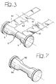
- a strip 50 of carbon fibre fabric is wrapped around on bell-shaped end 5 of the core 1 (e.g. five complete turns around the core). After this, the same operation is carried out on the strip of fabric 51 over the end 6 of the core 1.
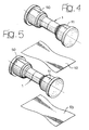
- Figure 4 illustrates the core 1 with two windings 50, 51 obtained at the end of the aforesaid phase.
- the strips 50 and 51 present triangular cuttings 50' and 51' to allow to such strips to enclose a tubular area with different diameters without leaving empty spaces or forming overlappings.
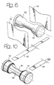
- a first piece, or ply, 52, a second ply 53 (figure 5), a fourth ply 54 and a fifth ply 55 (figure 6) are then applied to the body thus obtained in four subsequent phases.
- All the plies 52, 53, 54, 55 extend for the entire axial length of the core, while each one only partially covers the core in the circumferential direction. As can be seen in figures 5, 6, they are applied on four different sides, arranged at an angle of 90° one with respect to the other. Firstly, two plies 52, 53, which are diametrically opposite are applied, after which two other plies 54, 55, which are also diametrically opposite and oriented at 90° with respect to the plies 52, 53 are applied.
- FIG. 7 illustrates the structure obtained at the end of the phases illustrated in figures 5, 6.
- the function of the plies described above is very important, because the plies connect the strips on the end of the core thus providing axial resistance to the layered body.
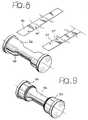
- two strips 56, 57 (presenting triangular cuttings 56' and 57' - figure 8) are wrapped over the applied layers in subsequent phases, in correspondence to the ends of the core so to obtain the structure shown in figure 9.
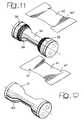
- two additional strips 58, 59 (presenting triangular cuttings 58' and 59') are additionally wrapped over the end of the core (figure 10), after which two additional plies 60, 61, (presenting triangular cuttings 60' and 61') which are diametrically opposite and which shape is shown in figure 11 are applied.
- the plies 60, 61 are obviously applied in two subsequent moments, to obtain the structure shown in figure 12, where said plies join the end layers so to additionally increase the axial resistance of the layered body.
- the method ends with the application of two additional strips 62, 63, (presenting triangular cuttings 62' and 63') which shape is shown in figure 13, which are wrapped around the ends of the core in two subsequent moments so to obtain the structure visible in figure 14, after which a last strip 64 is applied, which shape is shown in figure 15, and wrapped around the central part of the core, so to finally obtain the structure shown in figure 16.
- the illustrated strips 50, 51, 56, 57, 62, 63 present triangular cuttings 50', 51' 56', 57', 62' 63' on one side, but they could present triangular cuttings on both sides.
- Said strips can also present, on one or on both sides, cuttings of other shapes, such as circular, oval, squared, rectangular, rectilinear and so on, or any combination thereof, the cuttings being perpendicular or inclined with respect to the edges of the strips. Further, it is also possible to choose the number, the depth, the width and the inclination of the cuttings.
- the strips 50, 51, 56, 57, 62, 63 could also present, on one or on both sides, extensions of different shapes, such as circular, oval, squared, rectangular, triangular and so on, or any combination thereof, the extensions being perpendicular or inclined with respect to the edges of the strips. Further, it is also possible to choose the number, the depth, the width and the inclination of the extensions. Finally, a combination of cuttings and/or extensions, on one or on both sides of the strips can be chosen in such a way as to obtain substantially any kind of thickness and shape such as, for example, the ones showed in fig. 22.
- the strips and the plies are arranged alternately with each other, so as to achieve the best result in terms of thickness and axial resistance
- a tubular body 9 is formed on the core (figure 16) a central constant section 10, and two bell-shaped ends 11, 12, which diameter is larger. Furthermore, the thickness of the pre-formed tubular body 9 progressively increases from the central section 10 in the direction of the ends or, as can be seen in figure 17, there is a central part (A) of constant section, end parts (C) with constant section, but larger than the central one and intermediate parts (B) with increasing sections. Finally, the two ring end flanges 7, 8 of the core 1 axially contain the ends of the pre-formed tubular body 9.
- the assembly consisting of the core 1, comprising the two elements 3, 4 and the pre-formed tubular body 9 wrapped around it, is positioned in the cylindrical cavity 13 of a moulding apparatus 14 (see figure 18).
- the cylindrical cavity 13 is formed by an upper half mould 15 and a lower half mould 16, presenting a conformation which corresponds to that of the external surface of the hub to be obtained, i.e. substantially corresponding to the external surface of the pre-formed tubular body 9 illustrated in figure 16.
- the ends of the cavity 13 are closed by two caps 17, 18, which are fastened by means of screws 19 to two end flanges of the two half moulds 15, 16.
- Each of the two caps 17, 18 incorporates a central cylindrical case 20 in which a respective helical spring 21 is arranged.
- Each of the two helical springs 21 is axially interposed between a bottom wall 20a of the respective tubular case 20 and the respective end surface of the core 1.
- the two springs 21 elastically press the two elements 3, 4 of the core 1 against each other so that these elements are kept in contact corresponding to their contact plane 22, which is orthogonal to the axis 23 of the core 1.
- the mould After arranging the assembly consisting of the core 1 and the pre-formed tubular body 9 wrapped on the core inside the mould, the mould is taken to a temperature sufficient to cause the reticulation of the thermosetting plastic material matrix belonging to the tubular body 9, for example to a temperature comprised in the range from 80°C to 200°C. This temperature increase is maintained preferably for a time comprised in the range from 10 minutes to 3 hours, preferably in the range from 30 minutes to 3 hours. In this way, the thermosetting matrix reticulates, while the PTFE forming the two elements 3, 4 of the core 1 dilates. This dilation is mainly impressed radially outwards, since the flanges 7, 8 are pressed against the ends of the pre-formed tubular body 9 by the two springs 21.
- a cooling phase follows, then the mould is opened and the assembly comprising the core 1 and the body 9 arranged upon it, is extracted.
- the elements 3, 4 forming the core 1 are extracted in opposite directions from the body thus obtained, forming the wheel hub according to this invention.
- the hub thus obtained presents the particularity of being made of structural fibre material, typically carbon fibre material, and being made of a single part, despite the complex geometrical shape described above.
- the product can naturally be subjected to additional machining (e.g. a set of radial holes can be drilled in the two bell-shaped ends for engaging the spokes) which make the part usable as a bicycle wheel hub.
- hubs with different shapes illustrated in fig.22, can be obtained.
- symmetrical and asymmetrical hubs with respect to the intermediate plane hubs with one or two flanges in proximity of one or both ends and hubs with cross-shaped flanges.
- the core 1 is formed by two elements 3,4 of metal material, e.g. steel, and is externally covered with a sheath 24 made of a high thermal dilatation elastomeric material.
- the elastomeric material forming the aforesaid sheath has a thermal dilation coefficient exceeding 15x10 -5 mm/°C and a maximum continuous heat resistance temperature exceeding 100°C.
- the sheath is pre-formed according to the configuration of the core (figure 4) with a central cylindrical section and two bell-shaped end sections and is preferably dimensioned so to be applied onto the core by stretching it slightly so that the sheath is adherent to the core by effect of its elastic return.
- Each of the two caps 17, 18 incorporates a central cylindrical case 20 in which a respective helical spring 21 is arranged.
- Each of the two helical springs 21 is axially interposed between a bottom wall 20a of the respective tubular case 20 and the respective end surface of the core 1.
- the two springs 21 elastically press the two elements 3, 4 of the core 1 against each other so that these elements are kept in contact corresponding to their contact plane 22, which is orthogonal to the axis 23 of the core 1.
- the mould After arranging the assembly consisting of the core 1 and the pre-formed tubular body wrapped on the core inside the mould, the mould is taken to a temperature sufficient to cause the reticulation of the thermosetting plastic material matrix belonging to the tubular body 9, for example to a temperature comprised in the range from 80°C to 200°C. This temperature increase is maintained preferably for a time comprised in the range from 10 minutes to 3 hours, preferably in the range from 30 minutes to 3 hours. In this way, the thermosetting matrix reticulates, while the synthetic rubber forming the sheath that covers the two elements 3, 4 of the core 1 dilates.
- the apparatus illustrated in figure 20 can obviously be modified by arranging a wall of high thermal dilatation material of the type shown above in correspondence to the surface of the mould cavity again by using a core made of two metallic material elements 3, 4.
- the thermal dilation of the wall of the cavity would determine the application of a radial pressure from the outside inwards on the external surface of the pre-formed tubular body 9 which would thus be squeezed on the metallic core.
Landscapes
- Engineering & Computer Science (AREA)
- Mechanical Engineering (AREA)
- Chemical & Material Sciences (AREA)
- Composite Materials (AREA)
- Materials Engineering (AREA)
- Moulding By Coating Moulds (AREA)
- Moulds For Moulding Plastics Or The Like (AREA)
- Casting Or Compression Moulding Of Plastics Or The Like (AREA)
Abstract
Description
- This invention relates to a method for fabricating the hub of a bicycle wheel, an apparatus for implementing the method and the bicycle wheel hub obtained by means of the said method.
- The Applicant has recently conducted various studies and tests to make bicycle components, particularly bicycle wheel hubs, especially for spoke wheel competition bicycles, using structural fibre based material, typically carbon fibre based material. The advantage offered by this type of material is that of being lighter in weight with respect to the metallic materials used in the past given equal structural characteristics. Making a hub out of a single part of carbon fibre based material was difficult, at least utilising the technologies available at that time, due to the typical conformation of the bicycle wheel hub of the type described above. The hubs used in modern bicycle wheels present a complex cylindrical shape, with a central constant diameter section and two bell-shaped end sections with a wider diameter or other, even more complex, shapes. Additionally, it is desirable for the hub thickness to progressively increase from the central section towards the hub ends, so to ensure the necessary resistance characteristics in all areas of the hub, particularly on the ends, where the wheel spokes are anchored, while ensuring minimal weight at the same time.
- The need of making a tubular body with the complex shapes described above has made it impossible to make the hub from a single part of structural fibre material, such as carbon fibre material.
- The object of this invention is to overcome this technical problem.
- In view of achieving this object, the invention provides a method for fabricating a bicycle wheel hub, characterised in that it comprises the following steps:
- providing an expandable core,
- applying a number of layers of structural fibre fabric incorporated in a plastic material matrix around the core to form a layered tubular body of predetermined shape and thickness around the core,
- arranging the core with the layered tubular body formed thereon in the cavity of a mould,
- increasing the temperature of the mould to a value sufficient to cause reticulation of the plastic material matrix,
- expanding the core for applying a pressure on the tubular body inside the mould, and
- removing the tubular body from the mould and from the core, so as to obtain a bicycle hub formed of a single piece of structural fibre material.
- In a first embodiment, the expandable core is made of a synthetic material presenting a thermal dilatation coefficient exceeding 5x10-15 mm/°C and a maximum continuous heat resistance equal to at least 80°C, the expansion of the core being obtained through the dilation of the material forming the core when the temperature of the mould is increased.
- Preferably, in this embodiment, the material forming the core has a thermal dilation coefficient exceeding 9x10⁻⁵ mm/°C and a maximum continuous thermal resistance temperature exceeding 100°C.
- Again preferably, the material forming the core can be either PTFE (polytetrafluoroethene), or FEP (fluorinated ethene propene), or PCTFE (polychlorotrifluoroethene), or PVDF (polyfluorodivinylidene), or PE-HD (high density polyethylene).
- The use of PTFE is widely preferred, due to the anti-adherence properties of this material, which are useful for detaching the core from the structural fibre moulded body, as well as its high continuous thermal resistance (260°C), for its good thermal conductivity (0.25 W/m°C) and for its good thermal capacity (specific heat), equal to 1.045 kJ/kg°C.
- The method, which main phases are outlined above, can be used in general to make hubs of all shapes, also different from that described above. A highly preferred characteristic of this method is in the arrangement of the aforesaid core made of high thermal dilation synthetic material, preferably PTFE. This material presents the characteristic of being subject to high thermal dilation at relatively low temperatures, in the order of temperatures at which the plastic material in which the structural fibre fabric is incorporated reticulates.
- In a second embodiment of the method of the invention, the expandable core includes a body of metal material covered with a deformable sheath made of an elastomeric material, the expansion of the core being obtained through the dilation of the material forming the sheath when the temperature of the mould is increased.
- Preferably, in this embodiment, the elastomeric material forming the aforesaid sheath has a thermal dilation coefficient exceeding 15x10-5 mm/°C and a maximum continuous heat resistance temperature exceeding 100°C. Still preferably, this material is a synthetic rubber of the type marketed under the trademark AIRCAST 3700 by Airtech International Inc., Huntington Beach, California, USA.
- According to a further preferred feature of the second embodiment, the sheath is pre-formed according to the configuration of the core and is dimensioned in order to be applied on the core by slightly stretching it, so that the sheath adheres to the core due to its elasticity.
- In a third embodiment of the method of the invention, the expandable core includes a body of metal material without any deformable sheath. In this embodiment the metallic core is divided in sectors, which can be expanded by means of mechanical means or, if provided by elastomeric junctions, by means of a gas injected inside the metallic core.
- Structural fibre fabrics incorporated in a plastic material matrix are known and have been used for some time. They are made with yarn obtained from structural fibres, such as carbon fibres, for example. These fabrics are then subjected to a calendering process to associate them to a plastic material matrix, typically a thermosetting plastic material.
- In the method of the invention, the structural fibres are selected among carbon fibres, glass fibres, Kevlar fibres, or any combinations thereof.
- According to another important feature of the invention, the layers of fabric on the core comprise one or more fabric strips wrapped around at least one axially limited portion of the core, to confer thickness to the tubular body, as well as a plurality of fabric plies extending along the core axis, to confer resistance in the axial direction to the tubular body.
- Further features of the method of the invention are indicated in the appended claims 23-34.
- This invention also relates to an apparatus as set forth in claims 41-44.
- Finally, this invention also relates to a bicycle wheel hub, characterised in that it has a tubular body made of a plurality of layers of structural fibre fabric incorporated in a plastic material matrix, said layers including one or more fabric strips wrapped around at least one axially limited portion of the hub body as well as a plurality of fabric plies extending along the hub axis.
- This invention will be better explained by the following detailed descriptions with reference to the accompanying figures as non-limiting examples, whereas:
- figure 1 generally indicates a perspective view of the core belonging to the apparatus used in the method according to a first embodiment of this invention,
- figure 2 illustrates a perspective view of the two elements forming the core in figure 1 in a reciprocally distanced condition,
- figures from 3 to 15 are perspective views illustrating the various phases of applying the layers of the carbon fibre fabrics on the core shown in figure 1,
- figure 16 is a perspective view illustrating the core in figure 1 completely coated with layers of carbon fibre fabrics,
- figure 17 is a partial cross-section view of the assembly illustrated in figure 16, with two elements forming the core and the pre-formed tubular layered body over them,
- figure 18 is a cross-sectional view of the mould usable in the method according to the first embodiment,
- figures 19,20 are variant of figures 17,18 corresponding to a second embodiment of the invention,
- figure 21 is a perspective view of the sheath of elastomeric material which is used in the method according to the second embodiment, and
- figure 22 shows wheel hubs with different shapes.
- With reference to figure 1,
numeral 1 generically indicates a generally cylindrical core, consisting of twoseparate elements elements elements central section 2 presenting a constant diameter and two bell-shaped end sections ring flanges 7, 8. - With reference to figures from 3 to 16, the
core 1 is externally coated with layers of structural fibre based fabric (typically carbon based fabric) incorporated in a thermosetting plastic material matrix. The various phases of the layering process are illustrated in the figures from 3 to 15. - With reference to figure 3, in a first phase, a
strip 50 of carbon fibre fabric is wrapped around on bell-shaped end 5 of the core 1 (e.g. five complete turns around the core). After this, the same operation is carried out on the strip offabric 51 over theend 6 of thecore 1. Figure 4 illustrates thecore 1 with twowindings - The
strips - A first piece, or ply, 52, a second ply 53 (figure 5), a
fourth ply 54 and a fifth ply 55 (figure 6) are then applied to the body thus obtained in four subsequent phases. All theplies plies other plies plies - At the end. of the phase described above, two
strips 56, 57 (presenting triangular cuttings 56' and 57' - figure 8) are wrapped over the applied layers in subsequent phases, in correspondence to the ends of the core so to obtain the structure shown in figure 9. At this point, twoadditional strips 58, 59 (presenting triangular cuttings 58' and 59') are additionally wrapped over the end of the core (figure 10), after which twoadditional plies plies - The method ends with the application of two
additional strips last strip 64 is applied, which shape is shown in figure 15, and wrapped around the central part of the core, so to finally obtain the structure shown in figure 16. - The illustrated strips 50, 51, 56, 57, 62, 63 present triangular cuttings 50', 51' 56', 57', 62' 63' on one side, but they could present triangular cuttings on both sides. Said strips can also present, on one or on both sides, cuttings of other shapes, such as circular, oval, squared, rectangular, rectilinear and so on, or any combination thereof, the cuttings being perpendicular or inclined with respect to the edges of the strips. Further, it is also possible to choose the number, the depth, the width and the inclination of the cuttings. The
strips - As described, the strips and the plies are arranged alternately with each other, so as to achieve the best result in terms of thickness and axial resistance
- Once the method is ended, a tubular body 9 is formed on the core (figure 16) a central
constant section 10, and two bell-shaped ends 11, 12, which diameter is larger. Furthermore, the thickness of the pre-formed tubular body 9 progressively increases from thecentral section 10 in the direction of the ends or, as can be seen in figure 17, there is a central part (A) of constant section, end parts (C) with constant section, but larger than the central one and intermediate parts (B) with increasing sections. Finally, the tworing end flanges 7, 8 of thecore 1 axially contain the ends of the pre-formed tubular body 9. - The assembly consisting of the
core 1, comprising the twoelements cylindrical cavity 13 of a moulding apparatus 14 (see figure 18). Thecylindrical cavity 13 is formed by anupper half mould 15 and alower half mould 16, presenting a conformation which corresponds to that of the external surface of the hub to be obtained, i.e. substantially corresponding to the external surface of the pre-formed tubular body 9 illustrated in figure 16. The ends of thecavity 13 are closed by twocaps screws 19 to two end flanges of the twohalf moulds caps cylindrical case 20 in which a respectivehelical spring 21 is arranged. Each of the twohelical springs 21 is axially interposed between abottom wall 20a of the respectivetubular case 20 and the respective end surface of thecore 1. The two springs 21 elastically press the twoelements core 1 against each other so that these elements are kept in contact corresponding to theircontact plane 22, which is orthogonal to theaxis 23 of thecore 1. - After arranging the assembly consisting of the
core 1 and the pre-formed tubular body 9 wrapped on the core inside the mould, the mould is taken to a temperature sufficient to cause the reticulation of the thermosetting plastic material matrix belonging to the tubular body 9, for example to a temperature comprised in the range from 80°C to 200°C. This temperature increase is maintained preferably for a time comprised in the range from 10 minutes to 3 hours, preferably in the range from 30 minutes to 3 hours. In this way, the thermosetting matrix reticulates, while the PTFE forming the twoelements core 1 dilates. This dilation is mainly impressed radially outwards, since theflanges 7, 8 are pressed against the ends of the pre-formed tubular body 9 by the two springs 21. Consequently, a radial pressure is exerted outwards against the tubular body 9, which is thus pushed against the wall of thecylindrical cavity 13. In this way, a uniform pressure is applied on all the parts of the pre-formed tubular body 9, despite the complex conformation of the body illustrated herein, with bell-shaped ends and a progressively increasing thickness, from the centre to the ends. Naturally, during this phase, thesprings 21 allow the twoelements ring flanges 7, 8. - At the end of the reticulation phase, a cooling phase follows, then the mould is opened and the assembly comprising the
core 1 and the body 9 arranged upon it, is extracted. At this point, theelements core 1 are extracted in opposite directions from the body thus obtained, forming the wheel hub according to this invention. The hub thus obtained presents the particularity of being made of structural fibre material, typically carbon fibre material, and being made of a single part, despite the complex geometrical shape described above. The product can naturally be subjected to additional machining (e.g. a set of radial holes can be drilled in the two bell-shaped ends for engaging the spokes) which make the part usable as a bicycle wheel hub. - Many other kinds of hubs with different shapes, illustrated in fig.22, can be obtained. In particular, symmetrical and asymmetrical hubs with respect to the intermediate plane, hubs with one or two flanges in proximity of one or both ends and hubs with cross-shaped flanges.
- With reference to figures 19,20 and 21, which relate to a second embodiment of the method of the invention, the
core 1 is formed by twoelements sheath 24 made of a high thermal dilatation elastomeric material. Preferably, the elastomeric material forming the aforesaid sheath has a thermal dilation coefficient exceeding 15x10-5 mm/°C and a maximum continuous heat resistance temperature exceeding 100°C. - For example, said material forming the core sheath can be a synthetic rubber of the type marketed under the trademark AIRCAST 3700 by Airtech International Inc., Huntington Beach, California, USA. This material is preferred for its relatively high thermal dilation coefficient (15x10-5 mm/°C), as well as its high continuous heat resistance (232°C), for its good thermal conductivity (2.59 W/m°C) and for its good ultimate tensile stress (680%), which is important to facilitate removing the sheath from the internal surface of the finished product after extracting it from the module and after removing the core.
- The sheath is pre-formed according to the configuration of the core (figure 4) with a central cylindrical section and two bell-shaped end sections and is preferably dimensioned so to be applied onto the core by stretching it slightly so that the sheath is adherent to the core by effect of its elastic return.
- Apart from the above indicated different structure of the core, the method remains identical to that described above with reference to the first embodiment. The assembly consisting of the
core 1, comprising the twoelements sheath 24 and the pre-formed tubular body 9 wrapped around it, is positioned in thecylindrical cavity 13 of amoulding apparatus 14 formed by anupper half mould 15 and alower half mould 16, presenting a conformation which corresponds to that of the external surface of the hub to be obtained, i.e. substantially corresponding to the external surface of the pre-formed tubular body 9 illustrated in figure 21. The ends. of thecavity 13 are closed by twocaps screws 19 to two end flanges of the twohalf moulds caps cylindrical case 20 in which a respectivehelical spring 21 is arranged. Each of the twohelical springs 21 is axially interposed between abottom wall 20a of the respectivetubular case 20 and the respective end surface of thecore 1. The two springs 21 elastically press the twoelements core 1 against each other so that these elements are kept in contact corresponding to theircontact plane 22, which is orthogonal to theaxis 23 of thecore 1. - After arranging the assembly consisting of the
core 1 and the pre-formed tubular body wrapped on the core inside the mould, the mould is taken to a temperature sufficient to cause the reticulation of the thermosetting plastic material matrix belonging to the tubular body 9, for example to a temperature comprised in the range from 80°C to 200°C. This temperature increase is maintained preferably for a time comprised in the range from 10 minutes to 3 hours, preferably in the range from 30 minutes to 3 hours. In this way, the thermosetting matrix reticulates, while the synthetic rubber forming the sheath that covers the twoelements core 1 dilates. This dilation is mainly impressed radially outwards, since theflanges 7, 8 are pressed against the ends of the pre-formed tubular body 9 by the two springs. Consequently, a radial pressure is exerted outwards against the tubular body 9, which is thus pushed against the wall of thecylindrical cavity 13. In this way, a uniform pressure is applied on-all the parts of the pre-formed tubular body 9, despite the complex conformation of the body illustrated herein, with bell-shaped ends and a progressively increasing thickness, from the centre to the ends. Naturally, during this phase, thesprings 21 allow the twoelements sheath 24 against theangular flanges 7, 8. - At the end of the reticulation phase, and after a subsequent cooling phase, the mould is opened and the assembly comprising the
core 1 and the body 9 arranged upon it, is extracted. At this point, theelements sheath 24, which initially remains associated to the internal surface of the tubular body, is extracted by elastic deformation. The hub thus obtained presents the particularly of being made of structural fibre material, typically carbon fibre material, and being made of a single part, despite the complex geometrical shape described above. The product can naturally be subjected to additional machining (e.g. a set of radial holes can be drilled in the two bell-shaped ends for engaging the spokes) which makes the part usable as a bicycle wheel hub. - The third embodiment differs from the second one by the fact that the metallic core is divided in sectors and it is not covered by any deformable sheath. In this embodiment the radial pressure to the tubular body is applied by mechanical means which act on the inside of the core, or by arranging the junctions of the metallic sectors with an elastomeric material, by injecting gas inside the metallic core. After the reticulation of the fabric matrix is obtained, and after a subsequent cooling phase, the internal pressure is stopped and the core comes back to its original dimensions, allowing the two elements of the core to be extracted from the reticulated tubular body.
- Finally, the apparatus illustrated in figure 20 can obviously be modified by arranging a wall of high thermal dilatation material of the type shown above in correspondence to the surface of the mould cavity again by using a core made of two
metallic material elements - Naturally, numerous changes can be implemented to the construction and forms of embodiment of the invention herein envisaged, all comprised within the context of the concept characterising this invention, as defined by the following claims.
- For example, despite that this description and accompanying claims explicitly refer to a bicycle wheel hub, the method according to this invention can obviously be applied to manufacturing other components with a similar shape, particularly other bicycle components. Consequently, also these applications and the deriving products, fall within the scope of this invention.
Claims (70)
- Method for fabricating a bicycle wheel hub, characterised in that it comprises the following steps:providing an expandable core (1),applying a number of layers of structural fibre fabric incorporated in a plastic material matrix around the core (1) to form a layered tubular body (9) of predetermined shape and thickness around the core (1),arranging the core (1) with the layered tubular body (9) formed thereon in the cavity (13) of a mould (14),increasing the temperature of the mould (14) to a value sufficient to cause reticulation of the plastic material matrix,expanding the core (1) for applying a pressure on the tubular body (9) inside the mould, andremoving the tubular body (9) from the mould and from the core (1), so as to obtain a bicycle hub formed of a single piece of structural fibre material.
- Method according to claim 1, characterised in that the increase of temperature of the mould (14) and the expansion of the core (1) occur substantially simultaneously.
- Method according to claim 1, characterised in that the pressure on the tubular body (9) caused by said expanding step is substantially radial.
- Method according to claim 1, characterised in that a cooling phase is provided before removal of the tubular body from the mould.
- Method according to claim 1, characterised in that the expandable core (1) is made of a synthetic material presenting a thermal dilatation coefficient exceeding 5x10-15 mm/°C and a maximum continuous heat resistance equal to at least 80°C, the expansion of the core being obtained through the dilation of the material forming the core (1) when the temperature of the mould is increased-.
- Method according to claim 5, characterised in that the core has a thermal dilation coefficient exceeding 9x10⁻⁵ mm/°C and a maximum continuous heat resistance temperature exceeding 100°C.
- Method according to claim 6, characterised in that the material forming the core is either PTFE, or PCTFE, or PVDF, or PE-HD.
- Method according to claim 7, characterised in that the material forming the core is PTFE.
- Method according to claim 1, characterised in that said structural fibres are selected among: carbon fibres, glass fibres, Kevlar fibres, or any combinations thereof.
- Method according to claim 1, characterised in that said plastic material matrix is a thermosetting plastic material matrix.
- Method according to claim 1, characterised in that said temperature is comprised in the range from 80°C to 200°C.
- Method according to claim 11, characterised in that said temperature is maintained for a time comprised in the range from 10 minutes to three hours.
- Method according to claim 12, characterised in that said temperature is maintained for a time comprised in the range from 30 minutes to three hours.
- Method according to claim 1, characterised in that said core (1) presents a cylindrical central section (2) and two wider diameter end sections (5, 6).
- Method according to claim 1, characterised in that said core (1) consists of two separate, axially contiguous elements (3, 4), with a contact plane (22) orthogonal to the axis (23) of the core, in order to allow separation of the core (1) from the tubular body (9) after extraction from the mould (14).
- Method according to claim 14, characterised in that also said tubular body (9) is formed so as to present a cylindrical central section (10) and two enlarged end sections (11, 12).
- Method according to claim 14, characterised in that said tubular body (9) presents a progressively increasing thickness from said central section (10) towards the ends.
- Method according to claim 14, characterised in that said tubular body (9) has a central part (A) of substantially constant section, end parts (C) with substantially constant section, but larger that the central one and intermediate parts (B) with increasing sections.
- Method according to claim 14, characterised in that said two elements (3, 4) forming the core (1) incorporate two end ring flanges (7, 8) to axially limit the ends of the pre-formed tubular body (9).
- Method according to claim 1, characterised in that the expandable core includes a body of metal material covered with a deformable sheath (124) made of an elastomeric material, the expansion of the core being obtained through the dilation of the material forming the sheath (24) when the temperature of the mould is increased.
- Method according to claim 20, characterised in that the elastomeric material forming the aforesaid sheath (24) has a thermal dilation coefficient exceeding 15x10-5 mm/°C and a maximum continuous heat resistance temperature exceeding 100°C.
- Method according to claim 21, characterised in that the material forming the core is a synthetic rubber of the type marketed under the trademark AIRCAST 3700 by Airtech International Inc., Huntington Beach, California, USA.
- Method according to claim 20, characterised in that the sheath (24) is pre-formed according to the configuration of the core and is preferably dimensioned in order to be applied on the core by slightly stretching it so that the sheath adheres to the core due to its elasticity.
- Method according to claim 1, characterised in that the layers of fabric on the core comprise one or more fabric strips (50,51,56,57,58,59,62,63,64) wrapped around at least one axially limited portion of the core (1), as well as a plurality of fabric plies (54,55,60,61) extending along the core axis.
- Method according to claim 24, characterised in that at least some of said strips have cuttings (50',51',56',57',62',63') on at least one lateral edge thereof.
- Method according to claim 24, characterised in that at least some of said strips have extensions on at least one lateral edge thereof.
- Method according to claim 24, characterised in that at least some of said strips have a combination of cuttings and extensions on at least one lateral edge thereof .
- Method according to claim 25, characterised in that said cuttings are triangular.
- Method according to claim 25, characterised in that said cuttings are rectangular.
- Method according to claim 25, characterised in that said cuttings are rectilinear
- Method according to claim 24, characterized in that at least some of said strips (50,51,56,57,58,59,62,63,64) and at least some of said plies (54,55,60,61) are applied on the core alternated to each other.
- Method according to claim 31, characterized in that at least one of said strips is wrapped around each end portion of said core
- Method according to claim 31, characterized in that at least one of said strips is wrapped around an intermediate portion of said core.
- Method according to claim 31, characterized in that at least some of said plies extend for the entire length of the core.
- Method according to claim 31, characterized in that at least some of said plies cover the core only partly in the circumferential direction.
- Method according to claim 35, characterized in that said plies are applied on different sides of the core for forming a complete layer on the core.
- Method according to claim 36, characterized in that the plies are applied in pairs on diametrically opposite sides of the core.
- Method according to claim 37, characterized in that different pairs of plies are applied so as to be angularly spaced relative to each other on the core.
- Method according to claim 38, characterized in that two pairs of diametrically opposite plies are applied spaced by 90° relative to each other.
- Method according to claim 1, characterised in that the expandable core includes a body of metal material including a number of circumferentially arranged separate sectors, the expansion of the core being obtained through a radially outward movement of said sectors.
- Apparatus for fabricating a bicycle wheel hub characterised in that it comprisesa mould (14) with a cylindrical cavity (13),an expandable core (1), on which a number of layers of structural fibre fabric incorporated in a plastic material matrix are applied to form a layered tubular body (9), of predetermined shape and thickness,means for increasing the temperature of the mould (14) to a value sufficient to cause the reticulation of the plastic material matrix, andmeans to cause an expansion of the core (1), determining the application of a pressure on the tubular body (9) inside the mould.
- Apparatus according to claim 41, characterized in that said core (1) presents a cylindrical central section (2) and two wider diameter end sections (5, 6) and includes two separate, axially contiguous elements (3, 4), with a contact plane (22) orthogonal to the axis (23) of the core (1), in order to allow separation of the core (1) from the tubular body (9) after extraction from the mould,
- Apparatus according to claim 42, characterized in that said apparatus further includes spring means (20) for elastically pressing said two elements (3, 4) forming the core (1) one against the other.
- Apparatus according to claim 43, characterised in that it comprises a cylindrical cavity (13) closed by two caps (17, 18) each comprising a respective helical spring (21), which is axially interposed between the cap (17, 18) and the respective element (3, 4) of said core (1).
- Bicycle wheel hub, characterised in that it is obtained with a method according to any of claims 1-40.
- Bicycle wheel hub, characterised in that it has a tubular body (9) made of a plurality of layers of structural fibre fabric incorporated in a plastic material matrix, said layers including one or more fabric strips (50,51,56,57,58,59,62,63,64) wrapped around at least one axially limited portion of the hub body as well as a plurality of fabric plies (54,55,60,61) extending along the hub axis.
- Bicycle wheel hub according to claim 46, characterised in that at least some of said strips (50,51,56,57,58,59,62,63,64) and at least some of said plies (54,55,60,61) are alternated to each other.
- Bicycle wheel hub according to claim 46, characterized in that at least one of said wrapped strips is provided at one end portion of the hub.
- Bicycle wheel hub according to claim 46, characterized in that said wrapped strips are provided at both ends of the hub.
- Bicycle wheel hub according to claim 46, characterized in that at least one of said wrapped strips is provided at an intermediate portion of said core.
- Bicycle wheel hub according to claim 46, characterised in that at least some of said strips have cuttings (50',51',56',57',62',63') on at least one lateral edge thereof.
- Bicycle wheel hub according to claim 46, characterised in that at least some of said strips have extensions on at least one lateral edge thereof.
- Bicycle wheel hub according to claim 46, characterised in that at least some of said strips have a combination of cuttings and extensions on at least one lateral edge thereof.
- Bicycle wheel hub according to claim 51, characterised in that said cuttings are triangular.
- Bicycle wheel hub according to claim 51, characterised in that said cuttings are rectilinear.
- Bicycle wheel hub according to claim 46, characterized in that at least some of said plies extend for the entire length of the hub.
- Bicycle wheel hub according to claim 46, characterized in that at least some of said plies cover an angle of less than 360° in the circumferential direction.
- Bicycle wheel hub according to claim 57, characterized in that said plies are provided on different sides of the hub body for forming a complete layer of the body.
- Bicycle wheel hub according to claim 58, characterized in that the plies are provided in pairs on diametrically opposite sides of the hub body.
- Bicycle wheel hub according to claim 59, characterized in that different pairs of plies are provided which are angularly spaced relative to each other.
- Bicycle wheel hub according to claim 60, characterized in that two pairs of diametrically opposite plies are provided spaced by 90° relative to each other.
- Bicycle wheel hub according to claim 46, characterised in that it has a central cylindrical section (10) and two wider bell-shaped end sections (11, 12), the thickness of the hub tubular body (9) increasing progressively from the central section (10) towards the ends.
- Bicycle wheel hub according to claim 46, characterised in that said tubular body (9) has a central part (A) of constant section, end parts (C) with constant section, but larger that the central one and intermediate parts (B) with increasing sections.
- Bicycle wheel hub according to claim 46, characterized in that said structural fibres are selected among carbon fibres, glass fibres, Kevlar fibres, or any combinations thereof.
- Bicycle wheel hub according to claim 46, characterized in that the hub body has a shape which is symmetrical relative to an intermediate plane orthogonal to the hub axis.
- Bicycle wheel hub according to claim 46, characterized in that the hub body has a shape which is asymmetrical relative to an intermediate plane orthogonal to the hub axis.
- Bicycle wheel hub according to claim 46, characterized in that the hub body has a flange in proximity of-one of its ends.
- Bicycle wheel hub according to claim 67, characterized in that the hub body has a flange in proximity of each of its ends.
- Bicycle wheel hub according to claim 67 or 68, characterized in that said flange has an annular shape.
- Bicycle wheel hub according to claim 67 or 68, characterized in that said flange is cross-shaped.
Applications Claiming Priority (6)
| Application Number | Priority Date | Filing Date | Title |
|---|---|---|---|
| ITTO010117 | 2001-02-13 | ||
| IT2001TO000119A ITTO20010119A1 (en) | 2001-02-13 | 2001-02-13 | PROCEDURE FOR THE MANUFACTURE OF A BICYCLE WHEEL HUB, AND THE HUB SO OBTAINED. |
| IT2001TO000117A ITTO20010117A1 (en) | 2001-02-13 | 2001-02-13 | PROCEDURE FOR THE MANUFACTURE OF A BICYCLE WHEEL HUB, DEVICE FOR THE IMPLEMENTATION OF THE PROCEDURE, AND THE HUB SO OBTAINED. |
| IT2001TO000118A ITTO20010118A1 (en) | 2001-02-13 | 2001-02-13 | PROCEDURE AND DEVICE FOR THE MANUFACTURE OF A BICYCLE WHEEL HUB, AND THE HUB SO OBTAINED. |
| ITTO010118 | 2001-02-13 | ||
| ITTO010119 | 2001-02-13 |
Publications (2)
| Publication Number | Publication Date |
|---|---|
| EP1231047A1 true EP1231047A1 (en) | 2002-08-14 |
| EP1231047B1 EP1231047B1 (en) | 2004-01-14 |
Family
ID=27274256
Family Applications (1)
| Application Number | Title | Priority Date | Filing Date |
|---|---|---|---|
| EP02002684A Expired - Lifetime EP1231047B1 (en) | 2001-02-13 | 2002-02-06 | Method for fabricating a bicycle wheel hub, apparatus for implementing the method and hub thus obtained |
Country Status (7)
| Country | Link |
|---|---|
| US (4) | US6688704B2 (en) |
| EP (1) | EP1231047B1 (en) |
| JP (1) | JP2002321241A (en) |
| CN (1) | CN1308135C (en) |
| CZ (1) | CZ2002490A3 (en) |
| DE (1) | DE60200161T2 (en) |
| ES (1) | ES2213714T3 (en) |
Cited By (8)
| Publication number | Priority date | Publication date | Assignee | Title |
|---|---|---|---|---|
| FR2814114A1 (en) * | 2000-09-15 | 2002-03-22 | Campagnolo Srl | WHEEL HUB FOR BICYCLE |
| FR2855099A1 (en) | 2003-05-23 | 2004-11-26 | Mavic Sa | Lightweight hub for bicycle or similar vehicle has the hub supported on a lightweight tube with end fittings to secure the bearings and to connect to the forks |
| US7087128B2 (en) | 2003-10-08 | 2006-08-08 | Dt Swiss Inc. | Method for manufacturing bicycle components |
| FR2894874A1 (en) | 2005-12-16 | 2007-06-22 | Salomon Sa | Bicycle wheel hub of composition material has tubular shell of resincoated fibres and at least one layer of fibres in form of sleeve with braided structure |
| WO2009073890A1 (en) | 2007-12-06 | 2009-06-11 | Rodman William L | Alignment system and methods for composite assemblies |
| EP2559568A4 (en) * | 2010-04-12 | 2014-06-04 | Gokiso Giken Co Ltd | HUB TYPE DEVICE FOR BICYCLE |
| GB2485334B (en) * | 2010-10-11 | 2014-08-06 | Gkn Aerospace Services Ltd | Structure |
| WO2015162173A1 (en) * | 2014-04-23 | 2015-10-29 | Kringlan Composites Ag | Preform wheel rim |
Families Citing this family (30)
| Publication number | Priority date | Publication date | Assignee | Title |
|---|---|---|---|---|
| EP1231047B1 (en) * | 2001-02-13 | 2004-01-14 | Campagnolo Srl | Method for fabricating a bicycle wheel hub, apparatus for implementing the method and hub thus obtained |
| US7192097B2 (en) * | 2002-12-26 | 2007-03-20 | Raphael Schlanger | Vehicle wheel |
| WO2004089242A2 (en) * | 2003-04-04 | 2004-10-21 | Playtex Products, Inc. | A barrel for a tampon applicator assembly and methods of forming |
| DE10346689A1 (en) * | 2003-10-08 | 2005-05-04 | Dt Swiss Ag Biel | Process for the production of components for bicycles |
| US20050275561A1 (en) * | 2004-05-25 | 2005-12-15 | Kolda Clint D | Enclosed operating characteristic sensor for a bicycle component including an emitter for emitting an operating characteristic signal |
| USD545748S1 (en) * | 2004-05-28 | 2007-07-03 | Shimano Inc. | Bicycle hub lever |
| US20060145530A1 (en) * | 2004-05-28 | 2006-07-06 | Rinard Damon | Flangeless and straight spoked bicycle wheel set |
| US20060264288A1 (en) * | 2005-03-24 | 2006-11-23 | Allen Michael A | Composite chain and associated methods of use and manufacture |
| USD539718S1 (en) * | 2005-05-28 | 2007-04-03 | Shimano Inc. | Bicycle hub |
| US7823981B2 (en) * | 2007-09-20 | 2010-11-02 | Zero Products, Llc | Aerodynamic wheel hub |
| CN201231651Y (en) * | 2008-06-04 | 2009-05-06 | 廖元宏 | Novel wheel hub |
| DE102009015612A1 (en) * | 2009-04-02 | 2010-10-07 | Benteler Maschinenbau Gmbh | Method for manufacturing e.g. motor vehicle component, involves broadening fiber reinforcement, so that fiber reinforcement is fixed on inner wall of hollow container, and reinforcing expanded fiber reinforcement |
| TW201119886A (en) * | 2009-12-11 | 2011-06-16 | Shu-Wei Lin | Method for manufacturing bicycle hub and product thereof. |
| CN102114751B (en) * | 2009-12-31 | 2012-12-12 | 林书伟 | Manufacturing method and product of bicycle hub |
| US8512624B2 (en) * | 2010-01-05 | 2013-08-20 | Shu-Wei Lin | Manufacturing process for a bicycle hub and product thereof |
| JP5116779B2 (en) * | 2010-01-08 | 2013-01-09 | 書偉 林 | Bicycle hub manufacturing method and product |
| US8607647B1 (en) | 2011-05-31 | 2013-12-17 | Saris Cycling Group, Inc. | Bicycle power sensing system |
| US9651138B2 (en) | 2011-09-30 | 2017-05-16 | Mtd Products Inc. | Speed control assembly for a self-propelled walk-behind lawn mower |
| CN102490372B (en) * | 2011-12-12 | 2014-08-13 | 中国科学院宁波材料技术与工程研究所 | Method for forming carbon fiber pipe and die thereof |
| EP2653294A1 (en) | 2012-04-21 | 2013-10-23 | Shu-Wei Lin | Manufacturing method and structure of bicycle wheel hub |
| TW201404624A (en) * | 2012-07-18 | 2014-02-01 | Bin Chang | Hub reinforcement device of bicycle |
| TWI552849B (en) * | 2013-01-25 | 2016-10-11 | 瑩信工業股份有限公司 | Method of manufacturing composite wheel rim |
| CN103407019B (en) * | 2013-07-18 | 2016-05-04 | 航天材料及工艺研究所 | A kind of assembling die and the application in forming composite structural member thereof |
| CN104669651B (en) * | 2013-12-02 | 2017-01-25 | 江西昌河航空工业有限公司 | A pressurizing device for a closed-section pipe sleeve |
| US9610802B2 (en) | 2014-06-27 | 2017-04-04 | Enve Composites, Llc | Bicycle wheel hub with molded spoke holes |
| EP3285664B1 (en) * | 2015-04-23 | 2021-08-04 | Applied Medical Resources Corporation | Systems for tissue removal |
| TWI609773B (en) * | 2015-12-25 | 2018-01-01 | 翁慶隆 | Method for forming a composite pipe and the device thereof |
| CN106994788A (en) * | 2016-01-22 | 2017-08-01 | 翁庆隆 | Method and device for forming composite pipe fitting |
| CN107139359A (en) * | 2017-06-30 | 2017-09-08 | 山东非金属材料研究所 | Compression molding die with the composite product for extending laterally cavity |
| CN108656865A (en) * | 2018-05-28 | 2018-10-16 | 鼎镁(昆山)新材料科技有限公司 | A kind of novel rear hub transmission structure |
Citations (4)
| Publication number | Priority date | Publication date | Assignee | Title |
|---|---|---|---|---|
| US4126659A (en) * | 1976-07-09 | 1978-11-21 | Lockheed Aircraft Corporation | Method of making a hollow article |
| DE3406650A1 (en) * | 1984-02-24 | 1985-09-05 | Union Sils, van de Loo & Co GmbH, 5758 Fröndenberg | Wheel hub housing |
| US5246275A (en) * | 1987-08-21 | 1993-09-21 | Arredondo Jr Rene N | Wheel for bicycles and method of producing |
| DE4416796A1 (en) * | 1994-05-06 | 1995-11-09 | Hms Antriebssysteme Gmbh | Aerodynamic cycle wheel |
Family Cites Families (43)
| Publication number | Priority date | Publication date | Assignee | Title |
|---|---|---|---|---|
| US2794481A (en) * | 1955-02-04 | 1957-06-04 | Smith Corp A O | Method and apparatus for making fiber reinforced resin tubing |
| US3008277A (en) * | 1959-12-21 | 1961-11-14 | Schloss Morris | Rotary buff |
| US3369843A (en) * | 1965-07-16 | 1968-02-20 | Philip E. Prew | Laminated wheel and method of manufacture |
| DE1619237A1 (en) * | 1966-05-11 | 1971-03-11 | Bayer Ag | Process for the production of molded bodies, optionally provided with outer layers |
| GB1336791A (en) * | 1971-01-01 | 1973-11-07 | Coal Industry Patents Ltd | Dust suppression means for mining machines |
| US3865220A (en) * | 1972-05-30 | 1975-02-11 | Jr William A Thompson | Bicycle hub |
| US3917352A (en) * | 1973-03-12 | 1975-11-04 | Steven Douglas Gageby | Continuous-strand, fiber reinforced plastic wheel |
| US4017348A (en) * | 1975-03-10 | 1977-04-12 | Shumaker Gerald C | Method of making a composite vehicle wheel |
| US4213234A (en) * | 1976-04-20 | 1980-07-22 | Dunlop Limited | Method and apparatus for manufacturing vehicle wheel rims from spirally wound sheet metal |
| US4294490A (en) * | 1980-02-06 | 1981-10-13 | Motor Wheel Corporation | Fiber-reinforced composite wheel construction |
| US4514013A (en) * | 1979-02-22 | 1985-04-30 | Motor Wheel Corporation | Fiber-reinforced composite wheel construction |
| US4413860A (en) * | 1981-10-26 | 1983-11-08 | Great Lakes Carbon Corporation | Composite disc |
| US4532097A (en) * | 1981-12-28 | 1985-07-30 | Ford Motor Company | Method of forming fiber reinforced synthetic material wheel |
| US4721342A (en) * | 1981-12-28 | 1988-01-26 | Ford Motor Company | Fiber reinforced synthetic material wheel |
| DE3390100T1 (en) * | 1982-07-12 | 1985-07-11 | Enco Miljö I Anderstorp AB, Anderstorp | Method of making a hub shaped for a spoked wheel |
| DE3331142C2 (en) * | 1983-08-30 | 1986-05-07 | Weco Wehmeyer & Co Fahrzeug-Fahrzeugteile-Werke Gmbh & Co, 4806 Werther | Rear wheel hub body for two-wheelers and process for its manufacture |
| GB8426059D0 (en) | 1984-10-16 | 1984-11-21 | Automotive Prod Plc | Vehicle road wheel |
| US4749235A (en) * | 1984-11-21 | 1988-06-07 | The Budd Company | Composite wheel construction |
| US4636344A (en) * | 1984-11-21 | 1987-01-13 | The Budd Company | Method of molding fiber reinforced composite wheel |
| US4774043A (en) * | 1985-05-23 | 1988-09-27 | Volkswagen Aktiengesellschaft | Method for production of a hollow shaft of fiber-reinforced plastic |
| US4832414A (en) * | 1987-03-09 | 1989-05-23 | Kelsey-Hayes Company | Filament wound wheel and a method for manufacturing the same |
| JPS6478825A (en) * | 1987-09-19 | 1989-03-24 | Noriji Hattori | Manufacture of frp pipe |
| JPH0790826B2 (en) * | 1988-12-27 | 1995-10-04 | 財団法人自転車産業振興協会 | Method for manufacturing bicycle drop handlebar made of carbon fiber reinforced plastic |
| US5192384A (en) * | 1991-05-30 | 1993-03-09 | Kaiser Aerospace And Electronics Corporation | Methods for forming composite tubing having tapered ends |
| JPH05200901A (en) * | 1991-12-27 | 1993-08-10 | Yokohama Rubber Co Ltd:The | Continuous production method for fiber reinforced thermoplastic pipe |
| US5266249A (en) * | 1992-01-02 | 1993-11-30 | Fusion Composites, Inc. | Method of forming a fiber reinforced plastic structure |
| JPH0692101A (en) * | 1992-09-11 | 1994-04-05 | Bridgestone Corp | Resin wheel |
| FR2706354B1 (en) * | 1993-06-14 | 1995-09-01 | Aerospatiale | Method for producing hollow objects in composite material by winding-depositing on contact on an expandable mandrel and objects thus obtained. |
| JPH07137163A (en) * | 1993-06-18 | 1995-05-30 | Nippon Oil Co Ltd | Method for manufacturing tubular composite molded body |
| JPH0716866A (en) * | 1993-06-30 | 1995-01-20 | Yokohama Rubber Co Ltd:The | Rtm molding method using expansible core and molded product molded thereby |
| US5484506A (en) * | 1994-05-16 | 1996-01-16 | Sani-Tech Incorporated | Smooth bore welding of thermoplastic tubing |
| US5829844A (en) * | 1995-10-03 | 1998-11-03 | Union Gesellschaft Fur Metallndustrie Mbh | Wheel hub assembly and method of manufacturing the same |
| JPH09323364A (en) * | 1996-06-04 | 1997-12-16 | Toray Ind Inc | FRP cylinder and manufacturing method thereof |
| US5773108A (en) * | 1996-06-14 | 1998-06-30 | Lockheed Martin Corporation | Self-coiling composite band |
| JP4327949B2 (en) * | 1999-07-22 | 2009-09-09 | 藤倉ゴム工業株式会社 | Manufacturing method of shaft |
| US6409278B1 (en) * | 2000-02-02 | 2002-06-25 | Shimano Inc. | Spoke nipple for bicycle wheel |
| US6398313B1 (en) * | 2000-04-12 | 2002-06-04 | The Polymeric Corporation | Two component composite bicycle rim |
| NL1016108C2 (en) * | 2000-09-05 | 2002-03-07 | Prins Dokkum B V | Manufacture of composite wheel useful as truck wheel involves building up separate preforms, combining and compressing separate preforms into one whole, and impregnating compressed whole with synthetic resin |
| IT1320644B1 (en) * | 2000-09-15 | 2003-12-10 | Campagnolo Srl | WHEEL HUB FOR BICYCLE. |
| US6347839B1 (en) * | 2000-09-25 | 2002-02-19 | Polymeric Corporation The | Composite rim |
| IT1321025B1 (en) * | 2000-10-12 | 2003-12-30 | Campagnolo Srl | BICYCLE WHEEL HUB. |
| EP1231047B1 (en) * | 2001-02-13 | 2004-01-14 | Campagnolo Srl | Method for fabricating a bicycle wheel hub, apparatus for implementing the method and hub thus obtained |
| US20050104441A1 (en) * | 2003-11-19 | 2005-05-19 | Bertelson Peter C. | Fiber reinforced composite wheels |
-
2002
- 2002-02-06 EP EP02002684A patent/EP1231047B1/en not_active Expired - Lifetime
- 2002-02-06 DE DE60200161T patent/DE60200161T2/en not_active Expired - Fee Related
- 2002-02-06 ES ES02002684T patent/ES2213714T3/en not_active Expired - Lifetime
- 2002-02-08 CZ CZ2002490A patent/CZ2002490A3/en unknown
- 2002-02-11 CN CNB021080933A patent/CN1308135C/en not_active Expired - Fee Related
- 2002-02-13 US US10/073,410 patent/US6688704B2/en not_active Expired - Fee Related
- 2002-02-13 US US10/073,405 patent/US7041186B2/en not_active Expired - Fee Related
- 2002-02-13 JP JP2002035594A patent/JP2002321241A/en active Pending
-
2003
- 2003-07-08 US US10/615,000 patent/US7066558B2/en not_active Expired - Fee Related
-
2005
- 2005-06-10 US US11/149,507 patent/US7273258B2/en not_active Expired - Fee Related
Patent Citations (4)
| Publication number | Priority date | Publication date | Assignee | Title |
|---|---|---|---|---|
| US4126659A (en) * | 1976-07-09 | 1978-11-21 | Lockheed Aircraft Corporation | Method of making a hollow article |
| DE3406650A1 (en) * | 1984-02-24 | 1985-09-05 | Union Sils, van de Loo & Co GmbH, 5758 Fröndenberg | Wheel hub housing |
| US5246275A (en) * | 1987-08-21 | 1993-09-21 | Arredondo Jr Rene N | Wheel for bicycles and method of producing |
| DE4416796A1 (en) * | 1994-05-06 | 1995-11-09 | Hms Antriebssysteme Gmbh | Aerodynamic cycle wheel |
Cited By (13)
| Publication number | Priority date | Publication date | Assignee | Title |
|---|---|---|---|---|
| US7484812B2 (en) | 2000-09-15 | 2009-02-03 | Compagnolo S.R.L. | Wheel hub for bicycle |
| FR2814114A1 (en) * | 2000-09-15 | 2002-03-22 | Campagnolo Srl | WHEEL HUB FOR BICYCLE |
| US7481499B2 (en) | 2000-09-15 | 2009-01-27 | Campagnolo S.R.L. | Wheel hub for bicycle |
| FR2855099A1 (en) | 2003-05-23 | 2004-11-26 | Mavic Sa | Lightweight hub for bicycle or similar vehicle has the hub supported on a lightweight tube with end fittings to secure the bearings and to connect to the forks |
| US7252344B2 (en) | 2003-05-23 | 2007-08-07 | Salomon S.A. | Multi-piece composite hub assembly for a bicycle |
| US7087128B2 (en) | 2003-10-08 | 2006-08-08 | Dt Swiss Inc. | Method for manufacturing bicycle components |
| FR2894874A1 (en) | 2005-12-16 | 2007-06-22 | Salomon Sa | Bicycle wheel hub of composition material has tubular shell of resincoated fibres and at least one layer of fibres in form of sleeve with braided structure |
| WO2009073890A1 (en) | 2007-12-06 | 2009-06-11 | Rodman William L | Alignment system and methods for composite assemblies |
| EP2229266A4 (en) * | 2007-12-06 | 2012-02-22 | William L Rodman | Alignment system and methods for composite assemblies |
| EP2559568A4 (en) * | 2010-04-12 | 2014-06-04 | Gokiso Giken Co Ltd | HUB TYPE DEVICE FOR BICYCLE |
| GB2485334B (en) * | 2010-10-11 | 2014-08-06 | Gkn Aerospace Services Ltd | Structure |
| US9120250B2 (en) | 2010-10-11 | 2015-09-01 | Gkn Aerospace Services Limited | Structure comprising an annular housing made of composite material |
| WO2015162173A1 (en) * | 2014-04-23 | 2015-10-29 | Kringlan Composites Ag | Preform wheel rim |
Also Published As
| Publication number | Publication date |
|---|---|
| DE60200161T2 (en) | 2004-10-28 |
| CN1308135C (en) | 2007-04-04 |
| US7041186B2 (en) | 2006-05-09 |
| CZ2002490A3 (en) | 2002-10-16 |
| US20040094258A1 (en) | 2004-05-20 |
| CN1375406A (en) | 2002-10-23 |
| US20020108248A1 (en) | 2002-08-15 |
| US7273258B2 (en) | 2007-09-25 |
| JP2002321241A (en) | 2002-11-05 |
| ES2213714T3 (en) | 2004-09-01 |
| US6688704B2 (en) | 2004-02-10 |
| US20020109398A1 (en) | 2002-08-15 |
| EP1231047B1 (en) | 2004-01-14 |
| US7066558B2 (en) | 2006-06-27 |
| US20050253448A1 (en) | 2005-11-17 |
| DE60200161D1 (en) | 2004-02-19 |
Similar Documents
| Publication | Publication Date | Title |
|---|---|---|
| EP1231047B1 (en) | Method for fabricating a bicycle wheel hub, apparatus for implementing the method and hub thus obtained | |
| EP1231077B2 (en) | Method for producing a bicycle wheel rim and bicycle wheel rim obtained thereby | |
| US12220881B2 (en) | Flexible thermoplastic driveshaft | |
| US9688097B2 (en) | Method for producing composite bicycle rim | |
| US4395809A (en) | Manufacture of vibration dampers | |
| CN105904915A (en) | Rim for a vehicle and a method of manufacturing a fiber composite rim | |
| US4140165A (en) | Reinforced tire and method of manufacturing same | |
| US20080054715A1 (en) | Bicycle wheel hub | |
| WO2005016975A2 (en) | A solid rubber tire | |
| EP3725542B1 (en) | Non-pneumatic tire having block type reinforcement | |
| US11958322B2 (en) | Non-pneumatic tire having reinforced support structure | |
| US3502527A (en) | Method of making a helically grooved reinforced hose | |
| US10400855B2 (en) | Methods of coupling a flywheel rim and a shaft | |
| JP6428058B2 (en) | Stiffening ring and tire vulcanizing method using the same | |
| JP2022034664A (en) | Method for manufacturing airless tire | |
| JP2642930B2 (en) | Wheel and method and apparatus for manufacturing the wheel | |
| JPH09310715A (en) | Solid roller | |
| US7635444B2 (en) | Method of molding a tire | |
| JPH0524401U (en) | Bicycle rim | |
| TW505579B (en) | Method and apparatus for fabricating a bicycle wheel hub and hub thus obtained | |
| JPH0211443B2 (en) | ||
| JPH0353121B2 (en) |
Legal Events
| Date | Code | Title | Description |
|---|---|---|---|
| PUAI | Public reference made under article 153(3) epc to a published international application that has entered the european phase |
Free format text: ORIGINAL CODE: 0009012 |
|
| AK | Designated contracting states |
Kind code of ref document: A1 Designated state(s): AT BE CH CY DE DK ES FI FR GB GR IE IT LI LU MC NL PT SE TR |
|
| AX | Request for extension of the european patent |
Free format text: AL;LT;LV;MK;RO;SI |
|
| 17P | Request for examination filed |
Effective date: 20020627 |
|
| GRAH | Despatch of communication of intention to grant a patent |
Free format text: ORIGINAL CODE: EPIDOS IGRA |
|
| GRAH | Despatch of communication of intention to grant a patent |
Free format text: ORIGINAL CODE: EPIDOS IGRA |
|
| AKX | Designation fees paid |
Designated state(s): DE ES FR GB IT NL |
|
| GRAA | (expected) grant |
Free format text: ORIGINAL CODE: 0009210 |
|
| AK | Designated contracting states |
Kind code of ref document: B1 Designated state(s): DE ES FR GB IT NL |
|
| REG | Reference to a national code |
Ref country code: GB Ref legal event code: FG4D |
|
| REG | Reference to a national code |
Ref country code: IE Ref legal event code: FG4D |
|
| REF | Corresponds to: |
Ref document number: 60200161 Country of ref document: DE Date of ref document: 20040219 Kind code of ref document: P |
|
| REG | Reference to a national code |
Ref country code: ES Ref legal event code: FG2A Ref document number: 2213714 Country of ref document: ES Kind code of ref document: T3 |
|
| ET | Fr: translation filed | ||
| REG | Reference to a national code |
Ref country code: IE Ref legal event code: MM4A |
|
| PLBE | No opposition filed within time limit |
Free format text: ORIGINAL CODE: 0009261 |
|
| STAA | Information on the status of an ep patent application or granted ep patent |
Free format text: STATUS: NO OPPOSITION FILED WITHIN TIME LIMIT |
|
| 26N | No opposition filed |
Effective date: 20041015 |
|
| PG25 | Lapsed in a contracting state [announced via postgrant information from national office to epo] |
Ref country code: GB Free format text: LAPSE BECAUSE OF NON-PAYMENT OF DUE FEES Effective date: 20060206 |
|
| GBPC | Gb: european patent ceased through non-payment of renewal fee |
Effective date: 20060206 |
|
| PGFP | Annual fee paid to national office [announced via postgrant information from national office to epo] |
Ref country code: ES Payment date: 20090226 Year of fee payment: 8 |
|
| PGFP | Annual fee paid to national office [announced via postgrant information from national office to epo] |
Ref country code: NL Payment date: 20090224 Year of fee payment: 8 |
|
| PGFP | Annual fee paid to national office [announced via postgrant information from national office to epo] |
Ref country code: DE Payment date: 20090331 Year of fee payment: 8 |
|
| PGFP | Annual fee paid to national office [announced via postgrant information from national office to epo] |
Ref country code: FR Payment date: 20090217 Year of fee payment: 8 |
|
| REG | Reference to a national code |
Ref country code: NL Ref legal event code: V1 Effective date: 20100901 |
|
| REG | Reference to a national code |
Ref country code: FR Ref legal event code: ST Effective date: 20101029 |
|
| PG25 | Lapsed in a contracting state [announced via postgrant information from national office to epo] |
Ref country code: NL Free format text: LAPSE BECAUSE OF NON-PAYMENT OF DUE FEES Effective date: 20100901 Ref country code: FR Free format text: LAPSE BECAUSE OF NON-PAYMENT OF DUE FEES Effective date: 20100301 |
|
| PG25 | Lapsed in a contracting state [announced via postgrant information from national office to epo] |
Ref country code: DE Free format text: LAPSE BECAUSE OF NON-PAYMENT OF DUE FEES Effective date: 20100901 |
|
| REG | Reference to a national code |
Ref country code: ES Ref legal event code: FD2A Effective date: 20110405 |
|
| PG25 | Lapsed in a contracting state [announced via postgrant information from national office to epo] |
Ref country code: ES Free format text: LAPSE BECAUSE OF NON-PAYMENT OF DUE FEES Effective date: 20110323 |
|
| PG25 | Lapsed in a contracting state [announced via postgrant information from national office to epo] |
Ref country code: ES Free format text: LAPSE BECAUSE OF NON-PAYMENT OF DUE FEES Effective date: 20100207 |
|
| PGFP | Annual fee paid to national office [announced via postgrant information from national office to epo] |
Ref country code: IT Payment date: 20120223 Year of fee payment: 11 |
|
| PG25 | Lapsed in a contracting state [announced via postgrant information from national office to epo] |
Ref country code: IT Free format text: LAPSE BECAUSE OF NON-PAYMENT OF DUE FEES Effective date: 20140206 |