EP1230480B1 - Hybride anlage für die nutzung von wind- und solarenergie - Google Patents
Hybride anlage für die nutzung von wind- und solarenergie Download PDFInfo
- Publication number
- EP1230480B1 EP1230480B1 EP00987094A EP00987094A EP1230480B1 EP 1230480 B1 EP1230480 B1 EP 1230480B1 EP 00987094 A EP00987094 A EP 00987094A EP 00987094 A EP00987094 A EP 00987094A EP 1230480 B1 EP1230480 B1 EP 1230480B1
- Authority
- EP
- European Patent Office
- Prior art keywords
- elements
- solar
- wind
- branch
- hybrid system
- Prior art date
- Legal status (The legal status is an assumption and is not a legal conclusion. Google has not performed a legal analysis and makes no representation as to the accuracy of the status listed.)
- Expired - Lifetime
Links
- 230000008878 coupling Effects 0.000 claims abstract description 22
- 238000010168 coupling process Methods 0.000 claims abstract description 22
- 238000005859 coupling reaction Methods 0.000 claims abstract description 22
- 239000013078 crystal Substances 0.000 claims description 9
- 238000005452 bending Methods 0.000 claims description 3
- 239000000463 material Substances 0.000 description 5
- 238000005070 sampling Methods 0.000 description 5
- 238000004519 manufacturing process Methods 0.000 description 3
- 238000005457 optimization Methods 0.000 description 3
- 239000003990 capacitor Substances 0.000 description 2
- 238000010586 diagram Methods 0.000 description 2
- 239000010408 film Substances 0.000 description 2
- 238000009434 installation Methods 0.000 description 2
- 238000000034 method Methods 0.000 description 2
- 239000010409 thin film Substances 0.000 description 2
- 238000006243 chemical reaction Methods 0.000 description 1
- 238000010276 construction Methods 0.000 description 1
- 238000001816 cooling Methods 0.000 description 1
- 230000000694 effects Effects 0.000 description 1
- 238000009429 electrical wiring Methods 0.000 description 1
- 238000010438 heat treatment Methods 0.000 description 1
- 238000012432 intermediate storage Methods 0.000 description 1
- 238000013139 quantization Methods 0.000 description 1
- 238000001228 spectrum Methods 0.000 description 1
- 230000003068 static effect Effects 0.000 description 1
- 230000002123 temporal effect Effects 0.000 description 1
Images




Classifications
-
- F—MECHANICAL ENGINEERING; LIGHTING; HEATING; WEAPONS; BLASTING
- F03—MACHINES OR ENGINES FOR LIQUIDS; WIND, SPRING, OR WEIGHT MOTORS; PRODUCING MECHANICAL POWER OR A REACTIVE PROPULSIVE THRUST, NOT OTHERWISE PROVIDED FOR
- F03D—WIND MOTORS
- F03D5/00—Other wind motors
- F03D5/06—Other wind motors the wind-engaging parts swinging to-and-fro and not rotating
-
- F—MECHANICAL ENGINEERING; LIGHTING; HEATING; WEAPONS; BLASTING
- F03—MACHINES OR ENGINES FOR LIQUIDS; WIND, SPRING, OR WEIGHT MOTORS; PRODUCING MECHANICAL POWER OR A REACTIVE PROPULSIVE THRUST, NOT OTHERWISE PROVIDED FOR
- F03D—WIND MOTORS
- F03D5/00—Other wind motors
-
- H—ELECTRICITY
- H02—GENERATION; CONVERSION OR DISTRIBUTION OF ELECTRIC POWER
- H02N—ELECTRIC MACHINES NOT OTHERWISE PROVIDED FOR
- H02N2/00—Electric machines in general using piezoelectric effect, electrostriction or magnetostriction
- H02N2/18—Electric machines in general using piezoelectric effect, electrostriction or magnetostriction producing electrical output from mechanical input, e.g. generators
-
- H—ELECTRICITY
- H02—GENERATION; CONVERSION OR DISTRIBUTION OF ELECTRIC POWER
- H02S—GENERATION OF ELECTRIC POWER BY CONVERSION OF INFRARED RADIATION, VISIBLE LIGHT OR ULTRAVIOLET LIGHT, e.g. USING PHOTOVOLTAIC [PV] MODULES
- H02S10/00—PV power plants; Combinations of PV energy systems with other systems for the generation of electric power
- H02S10/10—PV power plants; Combinations of PV energy systems with other systems for the generation of electric power including a supplementary source of electric power, e.g. hybrid diesel-PV energy systems
-
- H—ELECTRICITY
- H02—GENERATION; CONVERSION OR DISTRIBUTION OF ELECTRIC POWER
- H02S—GENERATION OF ELECTRIC POWER BY CONVERSION OF INFRARED RADIATION, VISIBLE LIGHT OR ULTRAVIOLET LIGHT, e.g. USING PHOTOVOLTAIC [PV] MODULES
- H02S10/00—PV power plants; Combinations of PV energy systems with other systems for the generation of electric power
- H02S10/10—PV power plants; Combinations of PV energy systems with other systems for the generation of electric power including a supplementary source of electric power, e.g. hybrid diesel-PV energy systems
- H02S10/12—Hybrid wind-PV energy systems
-
- F—MECHANICAL ENGINEERING; LIGHTING; HEATING; WEAPONS; BLASTING
- F05—INDEXING SCHEMES RELATING TO ENGINES OR PUMPS IN VARIOUS SUBCLASSES OF CLASSES F01-F04
- F05B—INDEXING SCHEME RELATING TO WIND, SPRING, WEIGHT, INERTIA OR LIKE MOTORS, TO MACHINES OR ENGINES FOR LIQUIDS COVERED BY SUBCLASSES F03B, F03D AND F03G
- F05B2220/00—Application
- F05B2220/70—Application in combination with
- F05B2220/708—Photoelectric means, i.e. photovoltaic or solar cells
-
- F—MECHANICAL ENGINEERING; LIGHTING; HEATING; WEAPONS; BLASTING
- F05—INDEXING SCHEMES RELATING TO ENGINES OR PUMPS IN VARIOUS SUBCLASSES OF CLASSES F01-F04
- F05B—INDEXING SCHEME RELATING TO WIND, SPRING, WEIGHT, INERTIA OR LIKE MOTORS, TO MACHINES OR ENGINES FOR LIQUIDS COVERED BY SUBCLASSES F03B, F03D AND F03G
- F05B2220/00—Application
- F05B2220/70—Application in combination with
- F05B2220/709—Piezoelectric means
-
- Y—GENERAL TAGGING OF NEW TECHNOLOGICAL DEVELOPMENTS; GENERAL TAGGING OF CROSS-SECTIONAL TECHNOLOGIES SPANNING OVER SEVERAL SECTIONS OF THE IPC; TECHNICAL SUBJECTS COVERED BY FORMER USPC CROSS-REFERENCE ART COLLECTIONS [XRACs] AND DIGESTS
- Y02—TECHNOLOGIES OR APPLICATIONS FOR MITIGATION OR ADAPTATION AGAINST CLIMATE CHANGE
- Y02E—REDUCTION OF GREENHOUSE GAS [GHG] EMISSIONS, RELATED TO ENERGY GENERATION, TRANSMISSION OR DISTRIBUTION
- Y02E10/00—Energy generation through renewable energy sources
- Y02E10/50—Photovoltaic [PV] energy
-
- Y—GENERAL TAGGING OF NEW TECHNOLOGICAL DEVELOPMENTS; GENERAL TAGGING OF CROSS-SECTIONAL TECHNOLOGIES SPANNING OVER SEVERAL SECTIONS OF THE IPC; TECHNICAL SUBJECTS COVERED BY FORMER USPC CROSS-REFERENCE ART COLLECTIONS [XRACs] AND DIGESTS
- Y02—TECHNOLOGIES OR APPLICATIONS FOR MITIGATION OR ADAPTATION AGAINST CLIMATE CHANGE
- Y02E—REDUCTION OF GREENHOUSE GAS [GHG] EMISSIONS, RELATED TO ENERGY GENERATION, TRANSMISSION OR DISTRIBUTION
- Y02E10/00—Energy generation through renewable energy sources
- Y02E10/70—Wind energy
Definitions
- the invention relates to a hybrid system for the use of wind power and solar energy nor the preamble of claim 1. Such systems are used alternatively for the production of electrical energy.
- hybrid energy systems have been developed, as described, for example, in DE 296 21 822 U1 and in DE 296 07 243 U1.
- Such systems consist of the usual rotating wind turbines, attached to the frame structures large-scale solar modules and are integrated electrotechnically.
- These large-area solar modules consist of a large number of individual and interconnected solar cells. Initially, due to their dimensions, such systems can only be integrated poorly into the landscape or even into residential areas.
- a major disadvantage of such systems is that large-area Sofamwdule generate a high wind load that must be applied by the wear-the frame of the system. This leads to even more expensive constructions.
- the installation height of the solar modules is not important for energy production, ie they can be installed just as well on the floor.
- the production of solar modules is very expensive and waste-intensive, since the individual solar cells must be tailored to fit before they are arranged in solar modules and electrically interconnected.
- the invention is therefore based on the object, the wind vane elements and so that the solar cells optimally in a generic hybrid plant reduce and thereby the efficiency of the wind turbine part and the Solar system part increase.
- the particular advantage of the invention lies in the fact that the individual solar cells are not electrically connected to rigid modules. This makes it possible, by means of a corresponding scanning program, to combine the electrically optimal performance characteristics of the individual solar cells. This is necessary for an optimization of the energy yield, since the system represents a light-flooded object and the changing state of the sun and the movement of the solar cells in the wind influence the irradiation or shading of the individual solar cells.
- By means of dynamic interconnections of the respective same energy levels of solar cells serial, parallel or combined interconnections of solar cells are realized according to the electrical power principle.
- the resulting diversity of current orresdominierender circuits allow the use of a solar inverter for feeding in the grid. This eliminates the intermediate storage in batteries, whereby the utility value is significantly increased.
- the sporadic voltages generated by the piezocrystal transducers are suitably converted into useful electrical energy, for example, by buffer capacitors, in an inverter circuit or by pulse transformers. Since every imaginable, introduced into the piezoelectric crystals bending, torsion, etc. leads to electrical voltages, wind energy conversion is given even with constantly changing wind directions. It is expedient for reasons of cost not to transplant the piezocrystal transducers directly into the branch elements, but to classify them into pluggable coupling elements. As a result, the responsible for a large relative deformation, different material properties can be realized very easily.
- This type of coupling also makes it very easy to set up a network of many such coupling elements in the crown boxes, which has an advantageous effect on the effectiveness of the system. Since in an advantageous manner the parent elements and the pile elements are designed to be plugged together, such a system can be set to generate energy to any energy requirement but also to any design requirement. Also very advantageous is the design of the solar wind elements in the form of thin-film solar cells or solar films. They are light and flexible like leaves and not so easy to heat because they are cooled anytime and easily by any small wind draft.
- the hybrid plant for the use of wind and solar energy is approximately comparable in shape to the shape of a tree and therefore consists of one Trunk 1 and a crown, consisting of crown elements 2 and Kronengeagonist 3.
- the Kronenge65 3 is made connectable via couplings 4 with the crown element 2.
- Fig. 2 shows a crown element 2 with a plurality of couplings 4, which are arranged distributed in a loose or in a strict order on the circumference of the crown element 2.
- a flexible coupling element 5 is used in each of the clutches 4, which is connected on the side remote from the stem with a first-order branching element 6.
- the branch element 6 is also equipped with a coupling 7. Similar to the tree design, further branch elements 6 'of the second order and branch elements 6 "of the third and further orders follow the branch element 6.
- further coupling elements 5 are inserted at preferred points in the same manner ,
- each Windolarelement 8 is designed to accommodate wind loads and for receiving solar energy.
- Each Windsolarelement 8 is connected via a connecting line 9 with a computer not shown, which scans for a program each of the Windsolar electrode 8 in a short cycle, comparing all simultaneously determined solar energy values together and the Windsolar electrode 8 linked with the same energy level. 4.
- the structure of the coupling element 5 is shown in FIG. 4. Thereafter, radially evenly distributed piezocrystal transducers 10 are cast into the flexible coupling material, which are then connected via leads 11 to an electronic unit, not shown.
- the trunk 1 and the crown with all its elements is preferably made of a plastic, wherein the material properties in the area where the piezoelectric crystal transducers 10 are used, has greater flexibility, such as the material properties in the other areas. It is most expedient if the flexibility of the location region of the piezocrystal converter 10 is only so great that the dead weight of the connected elements is borne and the remaining elements are rigid. Thus, the largest mechanical deformation is directed to the piezoelectric crystal transducer 10, which convert the kinetic energy occurring into electrical voltage.
- the plurality of wind solar elements 8 are more or less exposed to the wind and the sun, with the individual wind solar elements 8 being in a different orientation to the sun and the wind and partially or completely obscured by other wind solar elements 8.
- individual wind solar elements deliver 8 different solar energy values.
- these solar energy values are constantly changing due to the changing state of the sun and the constant changes in the direction of the wind solar elements 8 caused by the wind.
- the large number of individual and different voltage and current values are fed in a short cycle to a computer, which detects and compares all these values.
- a selected performance diagram is shown in FIG. 5, according to which each wind solar element 8 has different solar energy values with respect to a specific temporal moment.
- the computer assigns the wind solar elements 8 to matching solar energy values and combines the same values having Windsolaretti 8.
- FIG. 5 shows three different power curves of wind solar elements 8 for illustrating the principle of scanning the power level of the wind solar elements 8.
- the difference in the power level of the wind solar elements 8 is based, as already described, on the different orientation to the sun, caused by wind movements, which can lead to shadowing.
- the sampling is based on the principle of the sampling method, whereby fast A / D converters sample and digitize the individual power curves according to the sampling frequency and the quantization levels.
- the graph in FIG. 5 shows three power curves of different wind solar elements 8 over a certain sampling period. The markings in the three power curves indicate that the same energy levels occur on the different power curves during the scan.
- the computer assigns the wind solar elements 8 to matching solar energy values and combines the same solar energy values having Windsolarieri 8. This in many of a few thousand solar cells and a corresponding clock rate is the guarantee of optimization over the entire power spectrum of the wind solar elements used. 8 The same wind solar elements 8 but also burdened by the wind and give this load.
Landscapes
- Engineering & Computer Science (AREA)
- Life Sciences & Earth Sciences (AREA)
- Sustainable Development (AREA)
- Sustainable Energy (AREA)
- Aviation & Aerospace Engineering (AREA)
- Chemical & Material Sciences (AREA)
- Combustion & Propulsion (AREA)
- Mechanical Engineering (AREA)
- General Engineering & Computer Science (AREA)
- Photovoltaic Devices (AREA)
- Wind Motors (AREA)
- Ink Jet Recording Methods And Recording Media Thereof (AREA)
Description
Solche Anlagen werden alternativ zur Gewinnung elektrischer Energie eingesetzt.
Zunächst lassen sich solche Anlagen aufgrund ihren Dimensionen gestalterisch nur mangelhaft in die Landschaft oder gar in Wohngebiete integrieren. Ein wesentlicher Nachteil solcher Anlagen besteht auch darin, daß großflächige Sofamwdule eine hohe Windlast erzeugen, die vom tragen-den Gestell der Anlage aufgebracht werden muß. Das führt zu noch aufwendigeren Konstruktionen.
Außerdem ist es aus Kostengründen unvertretbar, die Solarmodule am Mast einer Windkraftanlage zu montieren, nur um eine hybride Energieanlage zu erhalten. Die Montagehöhe der Solarmodule spielt für die Energiegewinnung keine Rolle, d. h. sie können eben so gut auf dem Boden installiert werden.
Dazu kommt, daß die Herstellung von Solarmodulen sehr kosten- und abfallintensiv ist, da die einzelnen Solarzellen paßgerecht zugeschnitten werden müssen, bevor sie zu Solarmodulen angeordnet und elektrisch verschaltet werden.
Allerdings bleibt der Nachteil aller Windkraftanlagen erhalten, der darin besteht, daß auf Grund der ständigen Rotation und der relativ großen Massen der sich drehenden Teile hohe Reibungsverluste auftreten, die den
Wirkungsgrad erheblich herabsetzen. Dieser generelle Nachteil wird noch dadurch verstärkt, daß die Solarmodule die Masse der Rotorflügel erhöhen und zu erhöhtem Reibungsverlust führen. Dazu kommt, daß die Einstellung der optimalen Anströmwinkel auf die Rotorblätter, relativ zum Wechsel der Windrichtung, nicht oder nur sehr träge erfolgen kann. Auch ist die Gesamtfläche aller Solarmodule durch die Anzahl und die Größe der Rotorflügel vorgegeben und damit begrenzt. Das schränkt die Anpassungsfähigkeit an spezielle Anwendungsfälle stark ein.
Auch ist der Aufwand für die Herstellung der auf den Rotorflügeln befindlichen Solarmodule sehr hoch.
Dadurch ist es möglich, durch ein entsprechendes Abtastprogramm, die elektrisch optimalen Leistungscharakteristiken der einzelnen Solarzellen zu kombinieren. Dies ist für eine Optimierung der Energieausbeute nötig, da die Anlage ein lichtdurchflutetes Objekt darstellt und der sich ändernde Stand der Sonne und die Bewegung der Solarzellen im Wind die Bestrahlung bzw. Abschattung der einzelnen Solarzellen beeinflussen. Es werden durch dynamische Zusammenschaltungen der jeweils gleichen Energieniveaus von Solarzellen, nach dem elektrischen Leistungsprinzip serielle, parallele oder kombinierte Verschaltungen von Solarzellen realisiert. Die sich hieraus ergebende Vielfalt strom- bzw. spannungsdominierender Schaltungen ermöglichen den Einsatz eines Solarinverters zur Netzeinspeisung. Damit entfällt die Zwischenspeicherung in Akkus, wodurch der Gebrauchswert wesentlich erhöht wird.
Die von den Piezokristall-Wandlern erzeugten sporadischen Spannungen werden in geeigneter Weise, zum Beispiel durch Pufferkondensatoren, in einer Wechselrichterschaltung oder durch Impulstransformatoren in verwertbare Elektroenergie umgewandelt.
Da jede nur denkbare, in die Piezokristalle eingebrachte Biegung, Torsion usw. zu elektrischen Spannungen führt, ist die Windenergieumwandlung auch bei ständig wechselnden Windrichtungen gegeben.
Es ist aus Kostengründen zweckmäßig, die Piezokristall-Wandler nicht direkt in die Astelemente zu verpflanzen, sondern in zusammensteckbare Kupplungselemente einzuordnen. Dadurch kann die für eine große relative Verformung verantwortliche, unterschiedliche Materialbeschaffenheit sehr einfach verwirklicht werden. Diese Kupplungsart ermöglicht auch sehr einfach, im Kronengeäst ein Netz von vielen solchen Kupplungselementen einzurichten, was sich vorteilhaft auf die Effektivität der Anlage auswirkt.
Da auch in vorteilhafter Weise die Stammelemente und die Pfahlelemente zusammensteckbar ausgeführt sind, kann eine solche Anlage zur Energiegewinnung auf jeden energetischen Bedarf aber auch an jede gestalterische Anforderung eingestellt werden.
Sehr vorteilhaft ist auch die Ausführung der Windsolarelemente in Form von Dünnschichtsolarzellen oder Solarfolien. Die sind leicht und flexibel wie Blätter und auch nicht so leicht erhitzbar, weil sie jederzeit und leicht von jedem kleinen Windzug gekühlt werden.
- Fig. 1:
- Stamm mit Kronenelementen,
- Fig. 2:
- ein Kronenelement in zwei Ansichten,
- Fig. 3:
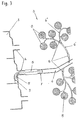
- einen Teilausschnitt der Astelemente mit den entsprechenden Kupplungselementen, sowie die Anordnung zum Kronenelement,
- Fig. 4:
- ein Kupplungselement in drei Ansichten,
- Fig. 5:
- ein Leistungsdiagramm von drei Windsolarelementen.
Stamm 1 und einer Krone, bestehend aus Kronenelementen 2 und Kronengeäst 3. Das Kronengeäst 3 ist über Kupplungen 4 mit dem Kronenelement 2 verbindbar ausgeführt. Die Fig. 2 zeigt ein Kronenelement 2 mit mehreren Kupplungen 4, die in einer losen oder in einer strengen Ordnung am Umfang des Kronenelements 2 verteilt angeordnet sind.
Gemäß der Fig. 3 ist in jeder der Kupplungen 4 ein flexibles Kupplungselement 5 eingesetzt, das auf der stammabgewandten Seite mit einem Astelement 6 erster Ordnung verbunden ist. Dazu ist das Astelement 6 ebenfalls mit einer Kupplung 7 ausgestattet. In Anlehnung an die Baumgestaltung schließen sich dem Astelement 6 weitere Astelemente 6' zweiter Ordnung und Astelemente 6" dritter und weiterer Ordnungen an. In diesen Astelementen 6, 6',6" sind an bevorzugten Stellen weitere Kupplungselemente 5 in der gleichen Art und Weise eingesetzt.
Jedes Windsolarelement 8 ist über eine Anschlußleitung 9 mit einem nichtdargestellten Rechner verbunden, der nach einem Programm jeder der Windsolarelemente 8 in kurzer Taktfolge abtastet, alle zeitgleich ermittelten Solarenergiewerte miteinander vergleicht und die Windsolarelemente 8 mit gleichen Energieniveau miteinander verknüpft.
Den Aufbau des Kupplungselementes 5 zeigt die Fig. 4. Danach sind radial gleichmäßig verteilt Piezokristall-Wandler 10 in das flexible Kupplungsmaterial eingegossen, die dann über Anschlußleitungen 11 mit einer nicht dargestellten Elektronik verbunden sind. Zur Verbindung der Windsolarelemente 8 mit der entsprechenden Elektronik sind alle Kupplungselemente
5 mit einem Kabelführungskanal 12 ausgerüstet.
Der Stamm 1 und die Krone mit allen ihren Elementen ist vorzugsweise aus einem Kunststoff gefertigt, wobei die Materialbeschaffenheit in dem Bereich, wo die Piezokristall-Wandler 10 eingesetzt sind, eine größere Flexibilität aufweist, wie die Materialbeschaffenheit in den übrigen Bereichen.
Am zweckmäßigsten ist es, wenn die Flexibilität der im Standortbereich der Piezokristall-Wandler 10 nur so groß ist, daß das Eigengewicht der verbundenen Elemente getragen wird und die übrigen Elemente starr ausgeführt sind. Damit wird die größte mechanische Verformung auf die Piezokristall-Wandler 10 gelenkt, die die auftretende Bewegungsenergie in elektrische Spannung umwandeln.
Die Vielzahl der Windsolarelemente 8 sind im einzelnen mehr oder weniger dem Wind und der Sonne ausgesetzt, wobei sich die einzelnen Windsolarelemente 8 in sich unterscheidender Ausrichtung zur Sonne und zum Wind befinden und auch teilweise oder völlig von anderen Windsolarelementen 8 verdeckt sind.
Die Vielzahl der einzelnen und unterschiedlichen Spannungs- und Stromwerte werden in kurzer Taktfolge einem Rechner zugeführt, der alle diese Werte erfaßt und miteinander vergleicht. Ein ausgewähltes Leistungsdiagramm zeigt die Fig. 5, wonach jedes Windsolarelement 8 unterschiedliche Solarenergiewerte bezogen auf einen bestimmten zeitlichen Moment aufweist. Im Vergleich aller ermittelten momentanen Solarenergiewerte ordnet der Rechner die Windsolarelemente 8 nach übereinstimmenden Solarenergiewerten und verknüpft gleiche Werte aufweisende Windsolarelemente 8. Wegen der sich ständig ändernden Bedingungen und den damit verbundenen Änderungen der Solarenergiewerte aller Windsolarelemente 8, ist die Koordination und Zusammenschaltung der passenden Windsolaretemente 8 ein ständiger und dynamischer Prozeß. Damit können serielle, parallele oder kombinierte Modulketten gebildet werden.
Fig. 5 zeigt zur Darstellung des Prinzips der Abtastung des Leistungsniveaus der Windsolarelemente 8 drei verschiedene Leistungskurven von Windsolarelementen 8.
Die Verschiedenheit des Leistungsniveaus der Windsolarelemente 8 beruht, wie schon beschrieben, auf der unterschiedlichen Ausrichtung zur Sonne, hervorgerufen durch Windbewegungen, die zu Abschattungen führen können.
Die Abtastung basiert auf dem Prinzip des Sampling-Verfahrens, wobei schnelle A/D Converter entsprechend der Samplingfrequenz und der Quantisierungsstufen die einzelnen Leistungskurven abtastet und digitalisiert.
Diese Daten werden einem Prozessor zugeführt, der durch Vergleich und Zuordnung im Moment der Abtastung die Windsolarelemente 8 nach Maßgaben der Leistungsoptimierung verknüpft.
Die Grafik in der Fig. 5 zeigt drei Leistungskurven, von unterschiedlichen Windsolarelementen 8 über einen bestimmten Abtastzeitraum. Dabei lassen die Markierungen in den drei Leistungskurven erkennen, daß während der Abtastung gleiche Energieniveaus auf den unterschiedlichen Leistungskurven auftreten. Im Vergleich aller ermittelten momentanen Solarenergiewerte ordnet der Rechner die Windsolarelemente 8 nach übereinstimmenden Solarenergiewerten und verknüpft gleiche Solarenergiewerte aufweisende Windsolarelemente 8. Dieses im Vielfach von ein paar Tausend Solarzellen und einer entsprechenden Taktrate gibt die Gewähr der Optimierung über das gesamte Leistungsspektrum der eingesetzten Windsolarelemente 8.
Die gleichen Windsolarelemente 8 werden aber auch vom Wind belastet und geben dieser Last nach. Die daraus entstehenden Bewegungen der W indsolarelemente 8 übertragen sich auf die betreffenden Astelemente 6, 6', 6" bis letztendlich auf die Kupplungselemente 5. Auf Grund der flexiblen Materialbeschaffenheit der Astelemente 6, 6', 6" in den Bereichen, wo die Piezokristall-Wandler 10 positioniert sind, treten hier die größten Biegespannungen und damit die größten Verformungen auf. Nach dem Ausführungsbeispiel trifft das auf die Kupplungselemente 5 zu.
Die Verformungen werden auf die Piezokristall-Wandlern 10 übertragen, die daraufhin elektrische Spannungen erzeugen. Diese Spannungen treten nur sporadisch auf und müssen deshalb durch Pufferkondensatoren in einer Wechselrichterschaltung oder durch Impulstransformatoren in verwertbare Elektroenergie umgewandelt werden, bevor sie durch die rechnergestützte Verschaltungselektronik weiter verarbeitet werden können und sich zur Elektroenergie der Solarzellen addieren.
Dabei erfolgt die Koordinierung der beiden Energiearten aus der Windkraft und der Sonne durch ein rechnergestütztes Programm, das den Gesetzen der FUZZY-LOGIC folgt.
- 1
- Stamm
- 2
- Kronenelement
- 3
- Kronengeäst
- 4
- Kupplung (Kronenelement)
- 5
- Kupplungselement
- 6
- Astelement
- 7
- Kupplung (Astelement)
- 8
- Windsolarelement
- 9
- Anschschlußleitung (Solar)
- 10
- Piezokristall-Wandler
- 11
- Anschlußleitung (Piezo)
- 12
- Kabelführungskanal
Claims (4)
- Hybride Anlage für die Nutzung von Wind- und Solarenergie, bestehend aus einem gemeinsamen Gestell mit mehreren tragenden Astelementen (6, 6', 6") und mehreren getragenen Windsolarelementen (8), wobei die tragenden Astelemente (6, 6', 6") mit mehreren schaltungstechnisch miteinander verknüpften Piezokristall-Wandler (10) ausgestattet sind und die getragenen Windsolarelemente (8) so ausgelegt sind, dass sie ein Biege- und/oder Drehmoment auf ausgewählte Bereiche der Astelemente (6, 6', 6") ausüben und glcichzeitig als Träger von miteinander verknüpften Solarzellen ausgebildet sind.
dadurch gekennzeichnet, dassdie Astelemente (6. 6'. 6'') in Astelemente erster Ordnung (6), zweiter Ordnung (6') und weiterer Ordnungen (6") verzweigt und die Astelemente (6, 6', 6") jeder Ordnung mit einem Piezokristall-Wandler (10) ausgestattet sind unddie auf den Windsolarelementen (8) befindlichen Solarzellen mit einem Rechner verbunden sind, der nach einem Programm jede Solarzelle in kurzer Taktfolge abtastet, alle zeitgleich ermittelten Werte miteinander vergleicht und Solarzellen mit gleichem Energieniveau verknüpft. - Hybride Anlage nach Anspruch 1.
dadurch gekennzeichnet, dass die Astelemente (6, 6', 6") durch Kupplungselemente (5) zusammensteckbar ausgeführt sind und die Piezokristall-Wandler (10) in die Kupplungselemente (5) eingebunden sind. - Hybride Anlage nach Anspruch 2,
dadurch gekennzeichnet, dass zur Abführung der Anschlussleitung (11) für die Piezokristall-Wandler (10) und der Anschlussleitung (9) für die Windsolarelemente (8) die Kronenelemente (2), die Kupplungselemente (5) und die Astelemente (6, 6', 6") mit einem Kabelführungskanal (12) ausgerüstet sind. - Hybride Anlage nach Anspruch 1,
dadurch gekennzeichnet, dass die Windsolarelemente (8) aus je einer Dünnschichtsolarzelle oder einer Solarfolie bestehen.
Applications Claiming Priority (3)
| Application Number | Priority Date | Filing Date | Title |
|---|---|---|---|
| DE19953632 | 1999-11-09 | ||
| DE19953632A DE19953632A1 (de) | 1999-11-09 | 1999-11-09 | Hybride Anlage für die Nutzung von Wind- und Solarenergie |
| PCT/DE2000/003901 WO2001034976A1 (de) | 1999-11-09 | 2000-11-08 | Hybride anlage für die nutzung von wind- und solarenergie |
Publications (2)
| Publication Number | Publication Date |
|---|---|
| EP1230480A1 EP1230480A1 (de) | 2002-08-14 |
| EP1230480B1 true EP1230480B1 (de) | 2005-07-27 |
Family
ID=7928257
Family Applications (1)
| Application Number | Title | Priority Date | Filing Date |
|---|---|---|---|
| EP00987094A Expired - Lifetime EP1230480B1 (de) | 1999-11-09 | 2000-11-08 | Hybride anlage für die nutzung von wind- und solarenergie |
Country Status (4)
| Country | Link |
|---|---|
| EP (1) | EP1230480B1 (de) |
| AT (1) | ATE300673T1 (de) |
| DE (3) | DE19953632A1 (de) |
| WO (1) | WO2001034976A1 (de) |
Families Citing this family (2)
| Publication number | Priority date | Publication date | Assignee | Title |
|---|---|---|---|---|
| WO2010131936A2 (en) * | 2009-05-15 | 2010-11-18 | Van Der Beka Evija | Nanoleaf |
| IT202200008738A1 (it) * | 2022-05-02 | 2023-11-02 | Iinformatica Srl | Sistema green per la generazione di energia pulita dal vento e da irradiazione luminosa tramite alberi, arbusti e piante e relativo metodo di generazione di energia pulita |
Family Cites Families (12)
| Publication number | Priority date | Publication date | Assignee | Title |
|---|---|---|---|---|
| DE2405134C2 (de) * | 1974-01-30 | 1985-08-08 | Reinhart Dipl.-Phys. Dr.-Ing. 1000 Berlin Radebold | Verfahren zur Speicherung von Exergie in Form freier Enthalpie chemischer Verbindungen und Anordnung zur Durchführung des Verfahrens |
| DE3017987A1 (de) * | 1980-05-10 | 1981-11-12 | Günter Dipl.-Ing. Dr. 2282 List Wagner | System zur ausnutzung von wind- und sonnenenergie |
| US4536674A (en) * | 1984-06-22 | 1985-08-20 | Schmidt V Hugo | Piezoelectric wind generator |
| DE3629804A1 (de) * | 1986-09-02 | 1988-03-03 | Heinrich Prof Dr Ing Reents | Verfahren mit den dazu gehoerigen vorrichtungen zur erzeugung von energie mit hilfe von kuenstlichen energiepflanzen |
| US5254876A (en) * | 1992-05-28 | 1993-10-19 | Hickey John J | Combined solar and wind powered generator with spiral blades |
| DE19502949A1 (de) * | 1995-01-31 | 1995-08-17 | Manfred Dr Baumgaertner | Anlage zur photo-voltaischen Stromerzeugung, bestehend aus Solarzellen und Halterung |
| DE19615943A1 (de) * | 1996-04-22 | 1997-10-23 | Uwe Kochanneck | Solaranlage |
| DE29607243U1 (de) * | 1996-04-23 | 1996-07-11 | Raschka, Jost, 78224 Singen | Windkraftanlage mit einem Tragmast für einen rotorgetriebenen Generator |
| DE29621822U1 (de) * | 1996-12-16 | 1997-02-20 | Bock, Manfred, Dipl.-Ing., 30455 Hannover | Vorrichtung zur Gewinnung von Solarstrom |
| DE29717984U1 (de) * | 1997-10-10 | 1998-01-02 | Beuermann, Herbert, Torremanzanas, Alicante | Wind-Solar-Generatoranlage |
| JPH11168228A (ja) * | 1997-12-03 | 1999-06-22 | Yasuhiro Fujita | 電樹.木ノ葉形状太陽光電池パネル発電.太陽光追尾装置 |
| DE19831692C2 (de) * | 1998-07-15 | 2003-12-24 | Thomas Gerhardt | Hybride Anlage für die Nutzung von Windkraft udn Solarenergie |
-
1999
- 1999-11-09 DE DE19953632A patent/DE19953632A1/de not_active Withdrawn
- 1999-11-09 DE DE29924309U patent/DE29924309U1/de not_active Expired - Lifetime
-
2000
- 2000-11-08 EP EP00987094A patent/EP1230480B1/de not_active Expired - Lifetime
- 2000-11-08 AT AT00987094T patent/ATE300673T1/de not_active IP Right Cessation
- 2000-11-08 DE DE50010840T patent/DE50010840D1/de not_active Expired - Lifetime
- 2000-11-08 WO PCT/DE2000/003901 patent/WO2001034976A1/de not_active Ceased
Also Published As
| Publication number | Publication date |
|---|---|
| DE29924309U1 (de) | 2002-11-28 |
| WO2001034976A1 (de) | 2001-05-17 |
| ATE300673T1 (de) | 2005-08-15 |
| DE50010840D1 (de) | 2005-09-01 |
| EP1230480A1 (de) | 2002-08-14 |
| DE19953632A1 (de) | 2001-05-23 |
Similar Documents
| Publication | Publication Date | Title |
|---|---|---|
| EP0494043B1 (de) | Vorrichtung zum Beschatten von Flächen mit einer aufgespannten Dachhaut und an dieser vorgesehenen photovoltaischen Elementen | |
| EP3742602A1 (de) | Photovoltaik-anlage und zugehörige verwendung | |
| WO2003038349A1 (de) | Solaranlage | |
| DE102019113016A1 (de) | Säule mit mindestens einem photovoltaischen Element und Verwendung eines photovoltaischen Elements an einer Säule | |
| DE202016008027U1 (de) | Photovoltaik-Anlage und zugehörige Verwendung | |
| DE102007051714A1 (de) | Photovoltaikanlage | |
| DE112015001881T5 (de) | Photoelektrische Stromerzeugungsvorrichtung | |
| DE102010029739B4 (de) | Solaranlage mit mehreren stromerzeugenden Folienelementen | |
| DE3937019A1 (de) | Kompaktvariables photovoltaikkraftwerk | |
| DE19831692C2 (de) | Hybride Anlage für die Nutzung von Windkraft udn Solarenergie | |
| DE4142566C2 (de) | Solaranlage mit auf einem räumlich gekrümmten Tragwerk angeordneten Solarmodulen | |
| DE202015100776U1 (de) | Turm mit einem Trägerkörper und Windturbine | |
| CH710234A2 (de) | Vorrichtung zur Erzeugung von elektrischer Energie aus Sonnenenergie und Windkraft. | |
| DE29703724U1 (de) | Windkraftanlage mit einem Tragmast für einen rotorgetriebenen Generator | |
| EP1230480A1 (de) | Hybride anlage für die nutzung von wind- und solarenergie | |
| DE10162116B4 (de) | Solaranlage | |
| DE29717984U1 (de) | Wind-Solar-Generatoranlage | |
| DE102019130374A1 (de) | Photovoltaikinstallation an einem Turm | |
| EP4049366B1 (de) | Photovoltaikmodul und photovoltaikanlage sowie verfahren zum betrieb einer solchen | |
| DE102019107786A1 (de) | Modulares Windkraftmodul mit einem vertikalen Mastelement und starr damit verbundenen Windturbinen | |
| DE202010002326U1 (de) | Dachsystem für Gebäude | |
| DE3231798A1 (de) | Verfahren zur herstellung eines solargenerators fuer solartechnische grossanlagen | |
| DE102023115218A1 (de) | Rundprofilhalterung | |
| DE202021101361U1 (de) | Solar-Tracker | |
| DE102022132079A1 (de) | Vorrichtung zur Erzeugung von elektrischer Energie |
Legal Events
| Date | Code | Title | Description |
|---|---|---|---|
| PUAI | Public reference made under article 153(3) epc to a published international application that has entered the european phase |
Free format text: ORIGINAL CODE: 0009012 |
|
| 17P | Request for examination filed |
Effective date: 20020607 |
|
| AK | Designated contracting states |
Kind code of ref document: A1 Designated state(s): AT BE CH CY DE DK ES FI FR GB GR IE IT LI LU MC NL PT SE TR |
|
| GRAP | Despatch of communication of intention to grant a patent |
Free format text: ORIGINAL CODE: EPIDOSNIGR1 |
|
| GRAS | Grant fee paid |
Free format text: ORIGINAL CODE: EPIDOSNIGR3 |
|
| GRAA | (expected) grant |
Free format text: ORIGINAL CODE: 0009210 |
|
| AK | Designated contracting states |
Kind code of ref document: B1 Designated state(s): AT BE CH CY DE DK ES FI FR GB GR IE IT LI LU MC NL PT SE TR |
|
| PG25 | Lapsed in a contracting state [announced via postgrant information from national office to epo] |
Ref country code: IT Free format text: LAPSE BECAUSE OF FAILURE TO SUBMIT A TRANSLATION OF THE DESCRIPTION OR TO PAY THE FEE WITHIN THE PRESCRIBED TIME-LIMIT;WARNING: LAPSES OF ITALIAN PATENTS WITH EFFECTIVE DATE BEFORE 2007 MAY HAVE OCCURRED AT ANY TIME BEFORE 2007. THE CORRECT EFFECTIVE DATE MAY BE DIFFERENT FROM THE ONE RECORDED. Effective date: 20050727 Ref country code: IE Free format text: LAPSE BECAUSE OF FAILURE TO SUBMIT A TRANSLATION OF THE DESCRIPTION OR TO PAY THE FEE WITHIN THE PRESCRIBED TIME-LIMIT Effective date: 20050727 Ref country code: TR Free format text: LAPSE BECAUSE OF FAILURE TO SUBMIT A TRANSLATION OF THE DESCRIPTION OR TO PAY THE FEE WITHIN THE PRESCRIBED TIME-LIMIT Effective date: 20050727 Ref country code: NL Free format text: LAPSE BECAUSE OF FAILURE TO SUBMIT A TRANSLATION OF THE DESCRIPTION OR TO PAY THE FEE WITHIN THE PRESCRIBED TIME-LIMIT Effective date: 20050727 Ref country code: GB Free format text: LAPSE BECAUSE OF FAILURE TO SUBMIT A TRANSLATION OF THE DESCRIPTION OR TO PAY THE FEE WITHIN THE PRESCRIBED TIME-LIMIT Effective date: 20050727 Ref country code: FI Free format text: LAPSE BECAUSE OF FAILURE TO SUBMIT A TRANSLATION OF THE DESCRIPTION OR TO PAY THE FEE WITHIN THE PRESCRIBED TIME-LIMIT Effective date: 20050727 |
|
| REG | Reference to a national code |
Ref country code: GB Ref legal event code: FG4D Free format text: NOT ENGLISH |
|
| REG | Reference to a national code |
Ref country code: CH Ref legal event code: EP |
|
| REG | Reference to a national code |
Ref country code: IE Ref legal event code: FG4D Free format text: LANGUAGE OF EP DOCUMENT: GERMAN |
|
| REF | Corresponds to: |
Ref document number: 50010840 Country of ref document: DE Date of ref document: 20050901 Kind code of ref document: P |
|
| PG25 | Lapsed in a contracting state [announced via postgrant information from national office to epo] |
Ref country code: GR Free format text: LAPSE BECAUSE OF FAILURE TO SUBMIT A TRANSLATION OF THE DESCRIPTION OR TO PAY THE FEE WITHIN THE PRESCRIBED TIME-LIMIT Effective date: 20051027 Ref country code: SE Free format text: LAPSE BECAUSE OF FAILURE TO SUBMIT A TRANSLATION OF THE DESCRIPTION OR TO PAY THE FEE WITHIN THE PRESCRIBED TIME-LIMIT Effective date: 20051027 Ref country code: DK Free format text: LAPSE BECAUSE OF FAILURE TO SUBMIT A TRANSLATION OF THE DESCRIPTION OR TO PAY THE FEE WITHIN THE PRESCRIBED TIME-LIMIT Effective date: 20051027 |
|
| PG25 | Lapsed in a contracting state [announced via postgrant information from national office to epo] |
Ref country code: ES Free format text: LAPSE BECAUSE OF FAILURE TO SUBMIT A TRANSLATION OF THE DESCRIPTION OR TO PAY THE FEE WITHIN THE PRESCRIBED TIME-LIMIT Effective date: 20051107 |
|
| PG25 | Lapsed in a contracting state [announced via postgrant information from national office to epo] |
Ref country code: AT Free format text: LAPSE BECAUSE OF NON-PAYMENT OF DUE FEES Effective date: 20051108 Ref country code: CY Free format text: LAPSE BECAUSE OF FAILURE TO SUBMIT A TRANSLATION OF THE DESCRIPTION OR TO PAY THE FEE WITHIN THE PRESCRIBED TIME-LIMIT Effective date: 20051108 |
|
| PG25 | Lapsed in a contracting state [announced via postgrant information from national office to epo] |
Ref country code: LU Free format text: LAPSE BECAUSE OF NON-PAYMENT OF DUE FEES Effective date: 20051130 Ref country code: BE Free format text: LAPSE BECAUSE OF NON-PAYMENT OF DUE FEES Effective date: 20051130 Ref country code: LI Free format text: LAPSE BECAUSE OF NON-PAYMENT OF DUE FEES Effective date: 20051130 Ref country code: CH Free format text: LAPSE BECAUSE OF NON-PAYMENT OF DUE FEES Effective date: 20051130 Ref country code: MC Free format text: LAPSE BECAUSE OF NON-PAYMENT OF DUE FEES Effective date: 20051130 |
|
| PG25 | Lapsed in a contracting state [announced via postgrant information from national office to epo] |
Ref country code: PT Free format text: LAPSE BECAUSE OF FAILURE TO SUBMIT A TRANSLATION OF THE DESCRIPTION OR TO PAY THE FEE WITHIN THE PRESCRIBED TIME-LIMIT Effective date: 20051227 |
|
| NLV1 | Nl: lapsed or annulled due to failure to fulfill the requirements of art. 29p and 29m of the patents act | ||
| GBV | Gb: ep patent (uk) treated as always having been void in accordance with gb section 77(7)/1977 [no translation filed] |
Effective date: 20050727 |
|
| REG | Reference to a national code |
Ref country code: IE Ref legal event code: FD4D |
|
| PLBE | No opposition filed within time limit |
Free format text: ORIGINAL CODE: 0009261 |
|
| STAA | Information on the status of an ep patent application or granted ep patent |
Free format text: STATUS: NO OPPOSITION FILED WITHIN TIME LIMIT |
|
| 26N | No opposition filed |
Effective date: 20060428 |
|
| REG | Reference to a national code |
Ref country code: CH Ref legal event code: PL |
|
| EN | Fr: translation not filed | ||
| PG25 | Lapsed in a contracting state [announced via postgrant information from national office to epo] |
Ref country code: FR Free format text: LAPSE BECAUSE OF FAILURE TO SUBMIT A TRANSLATION OF THE DESCRIPTION OR TO PAY THE FEE WITHIN THE PRESCRIBED TIME-LIMIT Effective date: 20060922 |
|
| BERE | Be: lapsed |
Owner name: GERHARDT, THOMAS Effective date: 20051130 |
|
| PG25 | Lapsed in a contracting state [announced via postgrant information from national office to epo] |
Ref country code: FR Free format text: LAPSE BECAUSE OF FAILURE TO SUBMIT A TRANSLATION OF THE DESCRIPTION OR TO PAY THE FEE WITHIN THE PRESCRIBED TIME-LIMIT Effective date: 20051130 |
|
| PG25 | Lapsed in a contracting state [announced via postgrant information from national office to epo] |
Ref country code: FR Free format text: LAPSE BECAUSE OF FAILURE TO SUBMIT A TRANSLATION OF THE DESCRIPTION OR TO PAY THE FEE WITHIN THE PRESCRIBED TIME-LIMIT Effective date: 20050727 |
|
| PGFP | Annual fee paid to national office [announced via postgrant information from national office to epo] |
Ref country code: DE Payment date: 20100527 Year of fee payment: 10 |
|
| REG | Reference to a national code |
Ref country code: DE Ref legal event code: R119 Ref document number: 50010840 Country of ref document: DE Effective date: 20110601 Ref country code: DE Ref legal event code: R119 Ref document number: 50010840 Country of ref document: DE Effective date: 20110531 |
|
| PG25 | Lapsed in a contracting state [announced via postgrant information from national office to epo] |
Ref country code: DE Free format text: LAPSE BECAUSE OF NON-PAYMENT OF DUE FEES Effective date: 20110531 |