EP1229680B1 - Modemratenschätzung mittels korrelation basierte qualitätsschätzung - Google Patents
Modemratenschätzung mittels korrelation basierte qualitätsschätzung Download PDFInfo
- Publication number
- EP1229680B1 EP1229680B1 EP02290212A EP02290212A EP1229680B1 EP 1229680 B1 EP1229680 B1 EP 1229680B1 EP 02290212 A EP02290212 A EP 02290212A EP 02290212 A EP02290212 A EP 02290212A EP 1229680 B1 EP1229680 B1 EP 1229680B1
- Authority
- EP
- European Patent Office
- Prior art keywords
- delivery
- noise factor
- noise
- pulse response
- motifs
- Prior art date
- Legal status (The legal status is an assumption and is not a legal conclusion. Google has not performed a legal analysis and makes no representation as to the accuracy of the status listed.)
- Expired - Lifetime
Links
- 230000004044 response Effects 0.000 claims abstract description 53
- 238000004364 calculation method Methods 0.000 claims description 24
- 230000005540 biological transmission Effects 0.000 claims description 16
- 238000000034 method Methods 0.000 claims description 16
- 230000004913 activation Effects 0.000 claims description 6
- 230000035945 sensitivity Effects 0.000 claims description 3
- 238000013213 extrapolation Methods 0.000 claims description 2
- 238000012384 transportation and delivery Methods 0.000 claims 17
- 238000012360 testing method Methods 0.000 abstract description 10
- 230000006870 function Effects 0.000 description 4
- 238000005259 measurement Methods 0.000 description 4
- 238000001228 spectrum Methods 0.000 description 4
- 230000000670 limiting effect Effects 0.000 description 3
- 238000012545 processing Methods 0.000 description 3
- 241001644893 Entandrophragma utile Species 0.000 description 2
- 238000001914 filtration Methods 0.000 description 2
- 230000010354 integration Effects 0.000 description 2
- 239000000523 sample Substances 0.000 description 2
- 238000012935 Averaging Methods 0.000 description 1
- 241001415961 Gaviidae Species 0.000 description 1
- 238000007796 conventional method Methods 0.000 description 1
- 238000012937 correction Methods 0.000 description 1
- 238000010219 correlation analysis Methods 0.000 description 1
- 230000003247 decreasing effect Effects 0.000 description 1
- 230000007547 defect Effects 0.000 description 1
- 230000000694 effects Effects 0.000 description 1
- 230000036961 partial effect Effects 0.000 description 1
- 230000003449 preventive effect Effects 0.000 description 1
- 230000000717 retained effect Effects 0.000 description 1
- 230000017105 transposition Effects 0.000 description 1
Images

Classifications
-
- H—ELECTRICITY
- H04—ELECTRIC COMMUNICATION TECHNIQUE
- H04L—TRANSMISSION OF DIGITAL INFORMATION, e.g. TELEGRAPHIC COMMUNICATION
- H04L1/00—Arrangements for detecting or preventing errors in the information received
- H04L1/0001—Systems modifying transmission characteristics according to link quality, e.g. power backoff
- H04L1/0015—Systems modifying transmission characteristics according to link quality, e.g. power backoff characterised by the adaptation strategy
- H04L1/0019—Systems modifying transmission characteristics according to link quality, e.g. power backoff characterised by the adaptation strategy in which mode-switching is based on a statistical approach
-
- H—ELECTRICITY
- H04—ELECTRIC COMMUNICATION TECHNIQUE
- H04L—TRANSMISSION OF DIGITAL INFORMATION, e.g. TELEGRAPHIC COMMUNICATION
- H04L1/00—Arrangements for detecting or preventing errors in the information received
- H04L1/0001—Systems modifying transmission characteristics according to link quality, e.g. power backoff
- H04L1/0002—Systems modifying transmission characteristics according to link quality, e.g. power backoff by adapting the transmission rate
-
- H—ELECTRICITY
- H04—ELECTRIC COMMUNICATION TECHNIQUE
- H04L—TRANSMISSION OF DIGITAL INFORMATION, e.g. TELEGRAPHIC COMMUNICATION
- H04L1/00—Arrangements for detecting or preventing errors in the information received
- H04L1/20—Arrangements for detecting or preventing errors in the information received using signal quality detector
Definitions
- the present invention relates to the commissioning of a connection of data transmission connecting two modems.
- modems can exchange data in such a way effective, they must characterize the link or channel linking them, ie determine the maximum rate for which data is received without errors.
- preactivation for a debit negotiation they exchange, at a previously specified rate, probing stimuli of the link in the form of pseudo-random patterns of online coding symbols, representing scrambled data bits according to a known polynomial, and the receiving modem analyzes the received analogue signal to determine its correlation with the expected pattern and thus measure the distortion brought by the binding, that is to say, the quality, more precisely the non-quality thereof, limiting the maximum possible flow.
- the correlation result For each type of modulation, a priori fixed by the structure of the modems, and for each bit rate and pattern, the correlation result provides an impulse response representing the energy received, distorted and tainted, the shape of which characterizes the ability of the link to be transmitted to high flows.
- US 5,870,429 discloses a device and method for determine the optimum flow rate among a range of possible flows in the context of the V24 protocol, thanks to the calculation of a threshold allowing to quickly locate the flow the nearest eligible. So we can not currently perform two error rate measurements in the bits received at two respective rates to attempt to interpolate the maximum possible flow, optimizing the efficiency of the link.
- the present invention aims at proposing a solution for determining this maximum throughput of the link.
- the invention also relates to a modem for implementing the method of the invention, comprising receiving means for receiving, of a data link, signals representing patterns of data symbols, the reception means controlling means for calculated to compare the received patterns with predetermined patterns and determining an impulse response curve of the link, characterized in that the calculation means are arranged to determine a plurality impulse response curve trains corresponding to a plurality of pattern trains at a plurality of respective rates, to compare between they impulse response curves of each train and determine relative differences representing a rate of noise at the flow rate of the train considered and the calculation means are arranged to compare the noise levels with a value predetermined threshold of high noise rate and determine a rate maximum.
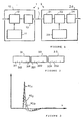
- FIG. 1 represents two modems 1, 2 connected by a connection 3 of data transmission, here a twisted pair of wires from a line telephone.
- the modem 1 is here represented by only a chain transmission 10 comprising a scrambling block 12, controlled by a block 11 for providing a scrambling polynomial, for scrambling bits generated locally (left arrow) and transmit them on link 3 across an interface block 13 comprising a signal transmitter adapted to physical characteristics of the link 3.
- the bits are transmitted in the form of data symbols each representing a block of bits of fixed length and of particular value.
- the modem 2 is here represented by only a chain of reception 20 comprising an interface 21 for receiving the symbols of the link 3, with here frequency transposition, which retransmits the symbols received at a correlation block 23, controlled by a block 22 for providing the sequences or correlation words used by the transmitter modem 1, block 23 providing the correlation results to a digital processing block 24 them.
- the modems 1 and 2 are here identical, that is to say that the modem 1 has a reception channel similar to that of modem 2, which itself has a transmission channel similar to that of the modem 1.
- FIG. 2 schematically represents trains of patterns of symbols emitted by the modem 1 in a pre-activation phase of the link 3.
- the aim of the pre-activation phase is to measure the distortion of propagation of the symbols provided by the link 3.
- the link 3 attenuates differently the various frequency components of the symbols, particularly attenuates those at high frequencies, and, moreover, link 3 propagates these components at different speeds, which causes intermodulation time overflows between symbols successive.
- Each symbol has a particular shape that corresponds to the value particular of the block of bits.
- the number of possible symbols is therefore equal to the number of different combinations of bits in a block of length determined.
- the trains 31, 32, 33 are respectively transmitted at three speeds or different rates D1, D2, D3, classified here by increasing values.
- the values P and N could also vary from one train to another.
- the receiving modem 2 performs, in block 23, the calculation of correlation of the P received symbol patterns with those expected, which provides P impulse response curves for each flow D.
- FIG. represents two impulse response curves, RI1 and RI2 at the rate D1.
- an impulse response has a peak shape of main impulse which weakens by oscillating, the axis of the abscissa representing a row of coefficients n, of which, in theory, only one represents the totality of the useful signal received and the others are null.
- each received symbol being distorted and noisy, its correlation with the shape of the symbol expected, or theoretical nominal form of the symbol issued, is not perfect and the spectrum of the amplitudes of the other coefficients represents the two defects mentioned above.
- each received symbol therefore consists of perform a correlation calculation with each of the possible symbols, and only the nominal symbol similar to the emitted symbol produces the peak above, the others providing only a flat answer.
- the correlation calculation providing a response curve like RI1 and RI2 is not just about a single symbol but on the sequence of the N symbols of a word.
- Activation of the link 3 consists, in the case of a process conventional method, to transmit, to the transmitting modem 1, the spectrum or histogram of coefficients of the average impulse response relative to a flow rate determined unique, so that the transmitter modem 1 applies a counter-distortion corresponding to the useful data that it will emit. Distortion being a stable characteristic, or slowly variable, one can predict its effects and therefore apply preventive measures. Noise is however essentially random and represents a state of affairs that must be limiting the flow.
- Link 3 is then activated to operate at an optimum rate, or maximum, determined from several of the D response curves impulse.
- the coefficients of correlation filtering, forming the histogram representing the curves above, are ranked in abscissa according to their rank n.
- impulse responses such as RI1, RI2 are compared to each other to measure their relative differences and to calculate or deducing a noise level of the considered pattern train 31, 32, 33, therefore at the flow rate D1, D2, D3 considered.
- the above deviations each expressed as a game of values of the coefficients, provide in fact, by cumulation and division by P for normalize the result, an absolute level of average noise.
- the noise level T is calculated by averaging the mean absolute noise level by the signal amplitude useful, that is substantially the amplitude of the peak of impulse response. It is conceivable that the division by P is optional since the final result, the T noise rate, is a ratio of two numbers each set from P values.
- the amplitudes of the peaks of the P responses pulses are substantially identical, one can conveniently use directly any of these amplitudes to normalize the noise, without to excessively distort the result.
- FIG. 4 represents the noise level T as a function of the flow Di of the link 3.
- D 3 points representing the three calculated pairs of noise-rate rate T1-D1, T2-D2, T3-D3.
- the noise level T increases with the flow Di, especially because low frequency filtering, or noise integration instantaneous, over the period symbol, has an efficiency that varies in the same meaning that the duration of this period, therefore decreasing at increasing rate.
- the horizontal line represents a high threshold S of admissible noise level, known by the literature to theoretically correspond to the minimum threshold of transmission quality of the link 3, for example a maximum error rate of 10 -9 , called BER (Bit Error Ratio) in the literature.
- BER Bit Error Ratio
- the value D0 is then communicated to the modem 1 transmitter of test trains, to activate link 3 at a limited rate depending on the flow rate maximum D0.
- bit rate of the modems 1, 2 is chosen at a value standardized among several possible, so that just below the rate D0 is selected to transmit useful data symbols to the emission power level initially retained.
- the noise independent of the wanted signal remains constant and the noise level T is shifted substantially by the same, in the opposite direction.
- a correction aimed at limiting this shift in the noise level T can possibly be provided, if it is considered that there is a significant noise related to the amplitude of the useful signal.
- the extrapolated curve or the interpolation curve is established from at least three calculated points of noise level, in order to take into account the curvature between them and thus better define the curve estimated with respect to a real curve of noise level according to the flow Di that it represents, here estimated from a discrete number (D) of points, that is, passing through, or near, these points.
- D discrete number
- the noise level can be expressed as a function of the amplitude of the average noise compared to that of a signal, possibly noisy as explained above since the result of the calculation of the report is not then substantially distorted.
- FIG. 5 represents the processing block 24, performing the calculations above.
- the coefficients representing the P impulse responses, each for N symbols, of a train 31, 32, 33 are stored in a memory 241 connected in output to a calculation block 242 which adds together the coefficients of the same rank to calculate the average impulse response RI0 after division by P.
- a calculation block 243 receives the coefficients representing the average impulse response RI0 and compares each average coefficient at the coefficient of the same rank of the P impulse responses RI1, RI2 of the 241 memory to determine, for each of them, a spectrum of deviations of its various coefficients in relation to the coefficients of the same rank of the average impulse response RI0.
- the average impulse response RI0 represents only the distortion of the link 3 to the flow D1 here considered, since the noise, a priori random and alternative, has been eliminated by the integration represented by the calculation of the average.
- Calculation block 243 squares N calculated gaps, for P words, and the N x P results are stored in a memory 244 homologous to the memory 241 but containing the quadratic differences, or variance, noise values and not the original amplitudes.
- a calculation block 245 then performs two pluralities (N, P) of summations, to add together, for each of the P words, the N quadratic differences of the word considered and for in besides adding between them these partial results in order to obtain the overall variance, the order of taking into account the N x P elementary quadradic values for accumulate them can be any.
- Block 245 After division by P, to normalize it, this global variance represents the energy or average power of the noise, which is then divided by the square of the average value of the impulse response RI0, previously received and squared by block 245 to represent the signal energy useful. Block 245 then calculates the useful signal / noise ratio, or noise / signal useful in the case of Figure 4, that is to say the power noise rate.
Landscapes
- Engineering & Computer Science (AREA)
- Quality & Reliability (AREA)
- Computer Networks & Wireless Communication (AREA)
- Signal Processing (AREA)
- Physics & Mathematics (AREA)
- Probability & Statistics with Applications (AREA)
- Digital Transmission Methods That Use Modulated Carrier Waves (AREA)
- Communication Control (AREA)
- Maintenance And Management Of Digital Transmission (AREA)
- Cable Transmission Systems, Equalization Of Radio And Reduction Of Echo (AREA)
Claims (9)
- Verfahren zur Inbetriebnahme einer Datenübertragungsverbindung (3), welche zwei Modems (1, 2) verbindet, wobei zum Charakterisieren der Verbindungsqualität in einer Anfangsphase der Voraktivierungwobei das Verfahren dadurch gekennzeichnet ist, daß in der Voraktivierungsphasedie Modems eine Folge (31) von vorgegebenen Mustern (311, 312) von Datensymbolen mit einem spezifischen Durchsatz (D1) und mit einem vorgegebenen Sendepegel austauschen, undjedes Modem (1, 2) eine Berechnung von Korrelationen zwischen den empfangenen Mustern (311, 312) und den erwarteten vorgegebenen Mustern durchführt, um Impulsantwortkurven (RI1, RI2) der Verbindung (3) bei dem spezifischen Durchsatz (D1) zu bestimmen und sie mit einer Kurve einer nominalen Impulsantwort zu vergleichen, um daraus Unterschiede zu bestimmen und somit eine Verbindungsqualität einzuschätzen, unddie Verbindung (3) aktiviert wird, wenn die Verbindungsqualität über einem vorgegebenen minimalen Schwellwert liegt,die Impulsantwortkurven (RI1, RI2) der empfangenen Muster (311, 312) miteinander verglichen werden, um ihre Relativabstände zu messen und daraus einen Rauschfaktor (T1) der Folge von Mustern (31) bei dem betrachteten Durchsatz (D1) zu berechnen, undsämtliche oben genannten Schritte für eine Vielzahl (D) von Folgen (31, 32, 33) durchgeführt werden, die jeweils einen spezifischen (D1, D2, D3) Durchsatz (Di) aufweisen,die Empfindlichkeit des Wertes für den Rauschfaktor (T1) bezogen auf den Durchsatz (Di) geschätzt wird durch Bestimmen einer Kurve für den Rauschfaktor, ausgehend von mindestens zwei Punkten, die zwei Paare von Werten für den Rauschfaktor mit zugeordnetem Durchsatz (T2-D2, T3-D3) darstellen,ein Wert für den maximal zulässigen Durchsatz (D0) gesucht wird, welcher dem Schnittpunkt der Kurve für den Rauschfaktor (T) mit einem hohen Rauschfaktorschwellwert (S) entspricht und theoretisch einem minimalen Schwellwert der zulässigen Qualität der Verbindung (3) entspricht, undder Wert des maximalen Durchsatzes (D0) zum Aktivieren der Verbindung (3) mit einem Wert, der in Abhängigkeit von dem maximalen Durchsatz (D0) beschränkt ist, an das Modem (1, 2) übertragen wird, welches die Folgen (31, 32, 33) sendet.
- Verfahren nach Anspruch 1,
bei dem zum Berechnen des Rauschfaktors bei jedem Durchsatzdie Impulsantworten (RI1, RI2) zusammengesetzt werden, um eine durchschnittliche Impulsantwort (RIO) zu erhalten, welche einen Durchschnitt des nützlichen empfangenen Signals darstellt,die Abstände der Impulsantworten (RI1, RI2) bezogen auf die durchschnittliche Impulsantwort (RIO) berechnet werden, undder Rauschfaktor ausgehend von den Abständen bezogen auf den Durchschnitt des nützlichen empfangenen Signals (RIO) berechnet wird. - Verfahren nach Anspruch 2,
bei dem jede Impulsantwort (RI1, RI2) durch einen Bereich von Koeffizienten mit einer vorgegebenen Anzahl dargestellt ist, wobei für jeden Durchsatz:die Abstände der verschiedenen Koeffizienten der verschiedenen Impulsantworten (RI1, RI2) mit den Koeffizienten eines gleichen Ranges der zugeordneten durchschnittlichen Impulsantwort (RIO) berechnet werden,der Quadratwert der Abstände berechnet wird, unddie Summe der Quadratwerte berechnet wird, um eine durchschnittliche Rauschleistung zu erhalten, welche mit der durchschnittlichen Leistung des Empfangssignals in ein Verhältnis gesetzt wird, um den Rauschfaktor zu erhalten. - Verfahren nach einem der Ansprüche 1 bis 3,
bei dem durch Herabstufen des Sendepegels der aktivierten Verbindung (3) um einen vorgegebenen Wert, bezogen auf den Sendepegel bei der Voraktivierung, der hohe Schwellwert des Rauschfaktors (5) relativ zu den berechneten Rauschfaktoren (T1, T2, T3) im wesentlichen so weit herabgestuft wird, daß ein neuer maximaler Durchsatz (D0) bestimmt wird. - Verfahren nach einem der Ansprüche 1 bis 4,
bei dem jedes Modem (1, 2) den von ihm bestimmten und den von dem anderen Modem (2, 1) bestimmten Wert des maximalen Durchsatzes (D0) vergleicht, um den niedrigeren Wert für bidirektionale Übertragungen auf der Verbindung (3) beizubehalten. - Verfahren nach einem der Ansprüche 1 bis 5,
bei dem die Kurve für den Rauschfaktor (T) durch Interpolation zwischen den berechneten Punkten bestimmt wird. - Verfahren nach einem der Ansprüche 1 bis 5,
bei dem die Kurve für den Rauschfaktor (T) durch Extrapolation von den berechneten Punkten bestimmt wird. - Modem zur Durchführung des Verfahrens nach Anspruch 1,
welches Empfangseinrichtungen (21) zum Empfangen von Signalen, welche Muster von Datensymbolen darstellen, von einer Datenübertragungsverbindung (3) aufweist, wobei die Empfangseinrichtungen (21) Recheneinrichtungen (22, 23, 24) steuern, welche dazu ausgelegt sind, die empfangenen Muster mit vorgegebenen Mustern zu vergleichen und daraus eine Impulsantwortkurve der Verbindung (3) zu bestimmen,
wobei das Modem dadurch gekennzeichnet ist, daß die Recheneinrichtungen (22, 23, 24) dazu ausgelegt sind, eine Vielzahl von Folgen von Impulsantwortkurven zu bestimmen, welche einer Vielzahl von Musterfolgen bei einer Vielzahl von jeweiligen Durchsätzen entsprechen, um die Impulsantwortkurven für jede Folge untereinander zu vergleichen und daraus relative Abstände zu bestimmen, die einen Rauschfaktor bei dem Durchsatz der betrachteten Folge darstellen,
und daß die Recheneinrichtungen (22, 23, 24) dazu ausgelegt sind, die Rauschfaktoren mit einem vorgegebenen Wert eines hohen Schwellwertes des Rauschfaktors zu vergleichen und daraus einen maximalen Durchsatz zu bestimmen. - Modem nach Anspruch 8,
bei dem die Recheneinrichtungen (22, 23, 24) dazu ausgelegt sind, für jede Folge eine durchschnittliche Impulsantwortkurve zu bestimmen und daraus eine entsprechende Energie zu berechnen, und ferner dazu ausgelegt sind, die Varianz der Impulsantwortkurven zu berechnen und den Rauschfaktor durch Berechnen des Verhältnisses zwischen der Varianz und der Energie der durchschnittlichen Impulsantwortkurve zu bestimmen.
Applications Claiming Priority (2)
| Application Number | Priority Date | Filing Date | Title |
|---|---|---|---|
| FR0101208 | 2001-01-30 | ||
| FR0101208A FR2820259B1 (fr) | 2001-01-30 | 2001-01-30 | Procede de mise en service d'une liaison de transmission de donnees reliant deux modems et modem correspondant |
Publications (2)
| Publication Number | Publication Date |
|---|---|
| EP1229680A1 EP1229680A1 (de) | 2002-08-07 |
| EP1229680B1 true EP1229680B1 (de) | 2005-06-15 |
Family
ID=8859382
Family Applications (1)
| Application Number | Title | Priority Date | Filing Date |
|---|---|---|---|
| EP02290212A Expired - Lifetime EP1229680B1 (de) | 2001-01-30 | 2002-01-30 | Modemratenschätzung mittels korrelation basierte qualitätsschätzung |
Country Status (5)
| Country | Link |
|---|---|
| EP (1) | EP1229680B1 (de) |
| AT (1) | ATE298154T1 (de) |
| DE (1) | DE60204606T2 (de) |
| ES (1) | ES2243666T3 (de) |
| FR (1) | FR2820259B1 (de) |
Family Cites Families (3)
| Publication number | Priority date | Publication date | Assignee | Title |
|---|---|---|---|---|
| US5870429A (en) * | 1996-06-17 | 1999-02-09 | Motorola, Inc. | Apparatus method, and software modem for utilizing envelope delay distortion characteristics to determine a symbol rate and a carrier frequency for data transfer |
| US5991273A (en) * | 1997-05-01 | 1999-11-23 | Nortel Networks Corporation | Determining SINR in a communications system |
| US6167031A (en) * | 1997-08-29 | 2000-12-26 | Telefonaktiebolaget Lm Ericsson (Publ) | Method for selecting a combination of modulation and channel coding schemes in a digital communication system |
-
2001
- 2001-01-30 FR FR0101208A patent/FR2820259B1/fr not_active Expired - Lifetime
-
2002
- 2002-01-30 DE DE60204606T patent/DE60204606T2/de not_active Expired - Lifetime
- 2002-01-30 AT AT02290212T patent/ATE298154T1/de not_active IP Right Cessation
- 2002-01-30 ES ES02290212T patent/ES2243666T3/es not_active Expired - Lifetime
- 2002-01-30 EP EP02290212A patent/EP1229680B1/de not_active Expired - Lifetime
Also Published As
| Publication number | Publication date |
|---|---|
| FR2820259B1 (fr) | 2003-05-02 |
| FR2820259A1 (fr) | 2002-08-02 |
| DE60204606D1 (de) | 2005-07-21 |
| DE60204606T2 (de) | 2006-05-11 |
| ES2243666T3 (es) | 2005-12-01 |
| ATE298154T1 (de) | 2005-07-15 |
| EP1229680A1 (de) | 2002-08-07 |
Similar Documents
| Publication | Publication Date | Title |
|---|---|---|
| EP0731573B1 (de) | Verfahren und Vorrichtung zur Überprufung eines Übertragungskanals in einem Kommunikationssystem | |
| FR2736229A1 (fr) | Procede d'echange adaptatif de bits et dispositif pour systeme a tons multiples discrets | |
| US8724689B2 (en) | Narrowband ingress estimation and characterization using equalizer taps | |
| EP0113487A1 (de) | Verfahren zur Anwendung in einer Echounterdrückungseinrichtung zur Messung einer Echoverzögerung und Vorrichtung zur Durchführung des Verfahrens | |
| EP0333167A1 (de) | Empfänger für Funkübertragungssysteme mit Raumdiversity, welcher einen Diversitykombinator enthält | |
| FR2525051A1 (fr) | Procede de reduction de l'energie des lobes lateraux d'un signal detectable en modulation a minimum | |
| EP0549445B1 (de) | Verfahren zur Übertragung von Referenzsignalen in einem Mehrträgerdatenübertragungssystem | |
| FR2833435A1 (fr) | Methode de selection de chemin de reception et dispositif de reception comprenant plusieurs chemins de reception | |
| EP1229680B1 (de) | Modemratenschätzung mittels korrelation basierte qualitätsschätzung | |
| EP1303071B1 (de) | Verfahren und Vorrichtung zur automatischen Ratenauswahl für Hochfrequenzübertragungen | |
| EP1105975A1 (de) | Iterativer rake-empfänger und entsprechendes empfangsverfahren | |
| FR2803467A1 (fr) | Methode d'estimation d'un canal de transmission ou de telecommunication | |
| FR2803468A1 (fr) | Methode d'estimation d'un canal de transmission ou de telecommunications | |
| EP1032169B1 (de) | System zur Schätzung der komplexen Verstärkung eines Übertragungskanals | |
| EP1334577B1 (de) | Verfahren und gerät zur schätzung des energiepegels eines funksignals | |
| EP2334021A1 (de) | Blindschätzmethode der OFDM-Modulationsparameter durch adaptiven Kovarianz | |
| EP0702467B1 (de) | Mittels Initialisierungsfolge synchronisierbares digitales Übertragungssystem | |
| FR2644654A1 (fr) | Procede de determination des coefficients d'un egaliseur non recursif | |
| FR2767433A1 (fr) | Procede de transmission de signaux a porteuses multiples avec un reglage de coefficients du correcteur dans le domaine temporel | |
| WO2006024712A1 (fr) | Procede de conception d'un filtre de reception numerique et dispositif de reception correspondant | |
| EP3462626A1 (de) | Cdma-kommunikationssystem, entsprechendes computerprogrammprodukt und entsprechendes kommunikationsverfahren | |
| WO2023247673A1 (fr) | Procédés d'émission et de réception d'une communication sans fil étalée spectralement à forte efficacité spectrale potentielle et dispositifs associés | |
| EP2276209B1 (de) | Verfahren zur Bestimmumg der Länge eines Kopffelds | |
| EP2079185A1 (de) | Vorrichtung und Verfahren der dynamischen und gleichberechtigten Zuordnung von Ressourcen eines Funknetzes vom OFDM-Typ | |
| EP1315347A1 (de) | Verfahren und Vorrichtung zur Entzerrung mit Probesignalen |
Legal Events
| Date | Code | Title | Description |
|---|---|---|---|
| PUAI | Public reference made under article 153(3) epc to a published international application that has entered the european phase |
Free format text: ORIGINAL CODE: 0009012 |
|
| AK | Designated contracting states |
Kind code of ref document: A1 Designated state(s): AT BE CH CY DE DK ES FI FR GB GR IE IT LI LU MC NL PT SE TR |
|
| AX | Request for extension of the european patent |
Free format text: AL;LT;LV;MK;RO;SI |
|
| 17P | Request for examination filed |
Effective date: 20030207 |
|
| AKX | Designation fees paid |
Designated state(s): AT BE CH CY DE DK ES FI FR GB GR IE IT LI LU MC NL PT SE TR |
|
| 17Q | First examination report despatched |
Effective date: 20031219 |
|
| GRAP | Despatch of communication of intention to grant a patent |
Free format text: ORIGINAL CODE: EPIDOSNIGR1 |
|
| GRAS | Grant fee paid |
Free format text: ORIGINAL CODE: EPIDOSNIGR3 |
|
| GRAA | (expected) grant |
Free format text: ORIGINAL CODE: 0009210 |
|
| AK | Designated contracting states |
Kind code of ref document: B1 Designated state(s): AT BE CH CY DE DK ES FI FR GB GR IE IT LI LU MC NL PT SE TR |
|
| PG25 | Lapsed in a contracting state [announced via postgrant information from national office to epo] |
Ref country code: AT Free format text: LAPSE BECAUSE OF FAILURE TO SUBMIT A TRANSLATION OF THE DESCRIPTION OR TO PAY THE FEE WITHIN THE PRESCRIBED TIME-LIMIT Effective date: 20050615 Ref country code: NL Free format text: LAPSE BECAUSE OF FAILURE TO SUBMIT A TRANSLATION OF THE DESCRIPTION OR TO PAY THE FEE WITHIN THE PRESCRIBED TIME-LIMIT Effective date: 20050615 Ref country code: TR Free format text: LAPSE BECAUSE OF FAILURE TO SUBMIT A TRANSLATION OF THE DESCRIPTION OR TO PAY THE FEE WITHIN THE PRESCRIBED TIME-LIMIT Effective date: 20050615 Ref country code: FI Free format text: LAPSE BECAUSE OF FAILURE TO SUBMIT A TRANSLATION OF THE DESCRIPTION OR TO PAY THE FEE WITHIN THE PRESCRIBED TIME-LIMIT Effective date: 20050615 Ref country code: IE Free format text: LAPSE BECAUSE OF FAILURE TO SUBMIT A TRANSLATION OF THE DESCRIPTION OR TO PAY THE FEE WITHIN THE PRESCRIBED TIME-LIMIT Effective date: 20050615 |
|
| REG | Reference to a national code |
Ref country code: CH Ref legal event code: EP Ref country code: GB Ref legal event code: FG4D Free format text: NOT ENGLISH |
|
| REF | Corresponds to: |
Ref document number: 60204606 Country of ref document: DE Date of ref document: 20050721 Kind code of ref document: P |
|
| REG | Reference to a national code |
Ref country code: IE Ref legal event code: FG4D Free format text: LANGUAGE OF EP DOCUMENT: FRENCH |
|
| PG25 | Lapsed in a contracting state [announced via postgrant information from national office to epo] |
Ref country code: DK Free format text: LAPSE BECAUSE OF FAILURE TO SUBMIT A TRANSLATION OF THE DESCRIPTION OR TO PAY THE FEE WITHIN THE PRESCRIBED TIME-LIMIT Effective date: 20050915 Ref country code: GR Free format text: LAPSE BECAUSE OF FAILURE TO SUBMIT A TRANSLATION OF THE DESCRIPTION OR TO PAY THE FEE WITHIN THE PRESCRIBED TIME-LIMIT Effective date: 20050915 Ref country code: SE Free format text: LAPSE BECAUSE OF FAILURE TO SUBMIT A TRANSLATION OF THE DESCRIPTION OR TO PAY THE FEE WITHIN THE PRESCRIBED TIME-LIMIT Effective date: 20050915 |
|
| GBT | Gb: translation of ep patent filed (gb section 77(6)(a)/1977) |
Effective date: 20050917 |
|
| PG25 | Lapsed in a contracting state [announced via postgrant information from national office to epo] |
Ref country code: PT Free format text: LAPSE BECAUSE OF FAILURE TO SUBMIT A TRANSLATION OF THE DESCRIPTION OR TO PAY THE FEE WITHIN THE PRESCRIBED TIME-LIMIT Effective date: 20051124 |
|
| NLV1 | Nl: lapsed or annulled due to failure to fulfill the requirements of art. 29p and 29m of the patents act | ||
| REG | Reference to a national code |
Ref country code: ES Ref legal event code: FG2A Ref document number: 2243666 Country of ref document: ES Kind code of ref document: T3 |
|
| REG | Reference to a national code |
Ref country code: IE Ref legal event code: FD4D |
|
| PG25 | Lapsed in a contracting state [announced via postgrant information from national office to epo] |
Ref country code: LU Free format text: LAPSE BECAUSE OF NON-PAYMENT OF DUE FEES Effective date: 20060131 Ref country code: MC Free format text: LAPSE BECAUSE OF NON-PAYMENT OF DUE FEES Effective date: 20060131 Ref country code: BE Free format text: LAPSE BECAUSE OF NON-PAYMENT OF DUE FEES Effective date: 20060131 Ref country code: CH Free format text: LAPSE BECAUSE OF NON-PAYMENT OF DUE FEES Effective date: 20060131 Ref country code: FR Free format text: LAPSE BECAUSE OF NON-PAYMENT OF DUE FEES Effective date: 20060131 Ref country code: LI Free format text: LAPSE BECAUSE OF NON-PAYMENT OF DUE FEES Effective date: 20060131 |
|
| PLBE | No opposition filed within time limit |
Free format text: ORIGINAL CODE: 0009261 |
|
| STAA | Information on the status of an ep patent application or granted ep patent |
Free format text: STATUS: NO OPPOSITION FILED WITHIN TIME LIMIT |
|
| 26N | No opposition filed |
Effective date: 20060316 |
|
| REG | Reference to a national code |
Ref country code: CH Ref legal event code: PL |
|
| REG | Reference to a national code |
Ref country code: FR Ref legal event code: ST Effective date: 20060929 |
|
| BERE | Be: lapsed |
Owner name: SAGEM S.A. Effective date: 20060131 |
|
| PG25 | Lapsed in a contracting state [announced via postgrant information from national office to epo] |
Ref country code: CY Free format text: LAPSE BECAUSE OF FAILURE TO SUBMIT A TRANSLATION OF THE DESCRIPTION OR TO PAY THE FEE WITHIN THE PRESCRIBED TIME-LIMIT Effective date: 20050615 |
|
| REG | Reference to a national code |
Ref country code: GB Ref legal event code: 732E Free format text: REGISTERED BETWEEN 20090319 AND 20090325 |
|
| REG | Reference to a national code |
Ref country code: GB Ref legal event code: 732E Free format text: REGISTERED BETWEEN 20090326 AND 20090401 |
|
| REG | Reference to a national code |
Country of ref document: DE Ref country code: DE Ref legal event code: R082 Ref document number: 60204606 Country of ref document: DE Representative=s name: , |
|
| REG | Reference to a national code |
Ref country code: DE Ref legal event code: R081 Ref document number: 60204606 Country of ref document: DE Owner name: SAGEMCOM SAS, FR Free format text: FORMER OWNER: SAGEM S.A., PARIS, FR Effective date: 20120120 |
|
| REG | Reference to a national code |
Ref country code: DE Ref legal event code: R081 Ref document number: 60204606 Country of ref document: DE Owner name: SAGEMCOM SAS, FR Free format text: FORMER OWNER: SAGEM TELECOMMUNICATIONS S. A., PARIS, FR Effective date: 20130129 |
|
| PGFP | Annual fee paid to national office [announced via postgrant information from national office to epo] |
Ref country code: GB Payment date: 20201218 Year of fee payment: 20 |
|
| PGFP | Annual fee paid to national office [announced via postgrant information from national office to epo] |
Ref country code: DE Payment date: 20201217 Year of fee payment: 20 Ref country code: ES Payment date: 20210201 Year of fee payment: 20 |
|
| PGFP | Annual fee paid to national office [announced via postgrant information from national office to epo] |
Ref country code: IT Payment date: 20210104 Year of fee payment: 20 |
|
| REG | Reference to a national code |
Ref country code: DE Ref legal event code: R071 Ref document number: 60204606 Country of ref document: DE |
|
| REG | Reference to a national code |
Ref country code: GB Ref legal event code: PE20 Expiry date: 20220129 |
|
| PG25 | Lapsed in a contracting state [announced via postgrant information from national office to epo] |
Ref country code: GB Free format text: LAPSE BECAUSE OF EXPIRATION OF PROTECTION Effective date: 20220129 |
|
| REG | Reference to a national code |
Ref country code: ES Ref legal event code: FD2A Effective date: 20220509 |
|
| PG25 | Lapsed in a contracting state [announced via postgrant information from national office to epo] |
Ref country code: ES Free format text: LAPSE BECAUSE OF EXPIRATION OF PROTECTION Effective date: 20220131 |