EP1229167A2 - Sound absorbing construction for track - Google Patents
Sound absorbing construction for track Download PDFInfo
- Publication number
- EP1229167A2 EP1229167A2 EP01128191A EP01128191A EP1229167A2 EP 1229167 A2 EP1229167 A2 EP 1229167A2 EP 01128191 A EP01128191 A EP 01128191A EP 01128191 A EP01128191 A EP 01128191A EP 1229167 A2 EP1229167 A2 EP 1229167A2
- Authority
- EP
- European Patent Office
- Prior art keywords
- sound absorbing
- track
- construction
- absorbing plate
- sound
- Prior art date
- Legal status (The legal status is an assumption and is not a legal conclusion. Google has not performed a legal analysis and makes no representation as to the accuracy of the status listed.)
- Granted
Links
Images


Classifications
-
- E—FIXED CONSTRUCTIONS
- E01—CONSTRUCTION OF ROADS, RAILWAYS, OR BRIDGES
- E01B—PERMANENT WAY; PERMANENT-WAY TOOLS; MACHINES FOR MAKING RAILWAYS OF ALL KINDS
- E01B19/00—Protection of permanent way against development of dust or against the effect of wind, sun, frost, or corrosion; Means to reduce development of noise
- E01B19/003—Means for reducing the development or propagation of noise
-
- E—FIXED CONSTRUCTIONS
- E01—CONSTRUCTION OF ROADS, RAILWAYS, OR BRIDGES
- E01B—PERMANENT WAY; PERMANENT-WAY TOOLS; MACHINES FOR MAKING RAILWAYS OF ALL KINDS
- E01B2/00—General structure of permanent way
Definitions
- the present invention relates to a sound absorbing construction for track used for railroad, monorail, or the like and, more particularly, to a sound absorbing construction for track in which a thin sound absorbing plate with a high impact strength formed of ceramic material or the like is provided.
- noises generated from railroad a noise under the vehicle floor, such as a rolling noise generated when wheels roll on rails, a motor fan noise generated from a fan for cooling a main motor, and a vehicle equipment noise generated from an inverter for control and a rectifier is known as a cause for noise pollution along railroad lines.
- a slab track has increasingly been used for railroad recently from the maintenance-free viewpoint. Because this track surface provides perfect reflection, noise reduction is required more urgently for the slab track than for a conventional ballast track. It is advantageous to take measures against noise at a position as close to the sound source as possible especially in terms of the efficiency of noise reduction. Therefore, a large reduction in noise can be achieved by providing a sound absorbing plate on or near the track surface.
- a material with a low impact strength lies on or near the track surface to absorb sound on the track surface, however, in addition to wind pressure and vibrations caused by cars running at a high speed, if a falling object such as a lump of ice falling from the back surface of vehicle body collides with the track surface, the sound absorbing material may be broken by the falling object or other flying objects. Furthermore, fragments of the material scatter, so that there is a fear that damage reaching secondary and tertiary accident or breakage may occur in the surroundings. Therefore, a material provided on or near the track surface must have sufficient impact resistance so as to be capable of withstanding impact caused by flying objects and a safe construction against possible breakage. Moreover, in the case where a sound absorbing plate is provided on or near the track surface, it is necessary to observe the regulation for clearance limit applied to the track, and also it is necessary to fully consider that there is a limit to track space.
- the ordinary ceramic sound absorbing material As a conventional sound absorbing material for track, the ordinary ceramic sound absorbing material, a lightweight aerated concrete sound absorbing material, and an inorganic particle bonding sound absorbing material are cited. There has been used a method in which these sound absorbing materials are arranged in the range close to the track.
- the thickness of material must be increased to control specific sound absorption.
- the weight of sound absorbing material increases undesirably, so that a heavy machine is needed to handle the sound absorbing material, resulting in an increase in cost of construction and maintenance.
- the sound absorbing material generally exhibits the highest sound absorbing properties when being subjected to noise in the perpendicular direction. Therefore, the most effective method for improving the sound absorption coefficient is to use a sound absorbing material construction subjected to noise perpendicularly from a sound source above the track.
- the inventors found that the above problems can be solved by providing a thin sound absorbing plate with a high impact strength on or near the track surface.
- the present invention has been completed from such a viewpoint.
- the present invention provides a sound absorbing construction for track which reduces a noise generated from a portion under the floor of a vehicle, such as a rolling noise generated when wheels roll on rails or a driving noise of an electric motor etc., of noises generated from a track, wherein a thin sound absorbing plate with a high impact strength is provided on a track close to the sound source or near a track.
- a composite ceramic sound absorbing plate formed by bonding an alumina-based ceramic material to an aluminum expanded metal can be used as the sound absorbing plate.
- the sound absorbing plate be installed so as to have a curved construction from the viewpoint of increased sound absorption efficiency. Also, since the sound absorbing plate has a sufficient sound absorption characteristics even if it is thin, it is preferable that the sound absorbing plate be installed in a limited space within the track so that the sound absorption frequency can be controlled by changing the thickness of back air layer formed between the sound absorbing plate and the bottom surface of track. Further, a grating is preferably provided over the sound absorbing plate from the viewpoint of increased maintainability and durability.
- the sound absorbing plate preferably used in the present invention is a composite ceramic sound absorbing plate formed by bonding an alumina-based ceramic material to an aluminum expanded metal, and this composite ceramic sound absorbing plate has a construction such that the surface thereof is covered with the aluminum expanded metal. Therefore, the composite ceramic sound absorbing plate has high impact resistance such that even if the sound absorbing material is damaged by an impact caused by a falling object or flying object, it is not broken and scattered owing to the aluminum expanded metal. Also, since the composite ceramic sound absorbing plate is featured by sufficient sound absorption characteristics even if the material thickness is as small as 6 to 9 mm, the sound absorption frequency can be controlled effectively by changing the back air layer even in a limited space within the track.
- the sound absorption frequency is changed for each tie section by changing the thickness of air layer for each tie interval, or noise can be reduced due to sound absorption for a wide frequency band by providing several kinds of sound absorption frequencies in a certain section. Inversely, a certain narrow frequency band can also be used.
- the composite ceramic sound absorbing plate can be formed so as to have a curvature, the sound absorbing material can be provided at a position opposed to the rail side face by disposing the sound absorbing material not only on the top face but also on the side face of a rectangular cross section. Therefore, the sound absorbing plate can be installed considering the optimum noise incident angle for rail noise, and also the sound absorption efficiency can be enhanced by forming the sound absorbing plate into a semicircular shape to increase the surface area.
- the sound absorbing construction in accordance with the present invention using a thin sound absorbing plate with a high impact strength such as a composite ceramic sound absorbing plate has a prominent sound absorbing effect and controllability of sound absorption frequency, and also has durability such as impact resistance.
- the sound absorbing construction is featured by ease of construction and maintenance and a low cost.
- FIG. 1 is a sectional view of a sound absorbing construction for track in accordance with an embodiment.
- a sound absorbing plate a composite ceramic sound absorbing plate in which an alumina-based ceramic material and an aluminum expanded metal are bonded to each other is used.
- This embodiment provides a sound absorbing construction in which a grating 2 is provided, and a thickness of air layer between a base frame 5 and a composite ceramic sound absorbing plate 1 can be controlled.
- the composite ceramic sound absorbing plate 1 is installed by being supported by support members 9 and a C channel 6.
- the support members 9 and the C channel 6 are carried by the base frame 5 provided under these elements, and the base frame 5 itself is fixed by various methods.
- the base frame 5 can be fixed to a tie 4 by driving nails, or it can be fixed with hole-in anchors in the case of concrete.
- it can be fixed by tightening bolts as shown in FIG. 1.
- this method can be applied to arbitrary ground surface formed of, for example, gravel or concrete.
- a distance from the plate 1 to the bottom surface of track can be regulated by changing the heights of the support members 9, the C channel 6, and the base frame 5.
- a sound absorption frequency region can be changed.
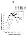
- FIG. 4 shows the relationship between sound absorption coefficient and frequency characteristics in a case where the thickness of back air layer-at the back of the composite ceramic sound absorbing plate used in the present invention is changed. This figure reveals that for the composite ceramic sound absorbing plate, the sound absorption frequency can be controlled by controlling the thickness of the back air layer.
- the sound absorption frequency characteristics region can be changed.
- the sound absorption coefficient can be changed by frequency appropriately at various rail laying locations.
- the height of the sound absorbing plate from the ground surface is regulated according to the frequency occurrence of sound in a high-pitched sound zone, a low-pitched sound zone, etc, by which the sound absorption efficiency can be optimized for a specific frequency.
- the composite ceramic sound absorbing plate used in this embodiment has a construction such that an alumina-based ceramic material and an aluminum expanded metal are bonded to each other.
- the thickness thereof is usually 5 to 10 mm, preferably 6 to 9 mm, and the weight thereof is usually 3 to 20 kg/m 2 , preferably 5 to 15 kg/cm 2 .
- the plate size is determined arbitrarily by the distance between the constructed rails and the construction range, and is not subject to any special restriction. Since the width between rails is usually in the range of 1067 to 1435 mm, the width of the sound absorbing plate is preferably in this range.
- the plate length in the direction parallel to the rails should be determined appropriately according to the method for conveying the plate and the location where the plate is installed.
- the above-described ceramic sound absorbing plate has excellent impact characteristics.
- the above-described ceramic sound absorbing plate 1 has an impact value of 14 kN-m/m 2 while an ordinary ceramic absorbing plate, a lightweight aerated concrete sound absorbing plate, and an inorganic particle bonding sound absorbing plate have impact values of 1.1, 1.0, and 0.8 kN-m/m 2 , respectively. That is to say, the above-described ceramic sound absorbing plate has an impact strength ten times or more the impact strengths of other sound absorbing plates. Therefore, the ceramic sound absorbing plate 1 of this embodiment is not broken by the ordinary impact, and is less liable to be broken even if being subjected to a high impact, the failure being able to be restricted to cracking or the like failure.
- a place between the two rails is generally used not only as a passage for railroad workers engaging in maintenance service but also as a passage for emergency, so that the place must be in a state in which persons can pass by.
- the ceramic sound absorbing plate 1 is installed between the rails 3, and the wire net-form or lattice-form grating 2 is provided over the composite ceramic sound absorbing plate 1.
- the means for installing the grating 2 is not subject to any restriction. For example, there is used a construction in which mounting members 8 are provided at both ends in the width direction of the grating, and the grating 2 is mounted on the mounting members 8. The size of the surface of the grating 2 can be determined arbitrarily.
- This embodiment offers an advantage that a passage for maintenance can be secured by providing the grating 2, and at the same time, offers an advantage that the grating 2 has a function of serving as a protector for the ceramic sound absorbing plate against lumps of ice falling from a running vehicle in cold weather.
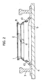
- FIG. 2 is a sectional view of a sound absorbing construction for track in accordance with a second embodiment.
- This embodiment provides, in addition to the construction shown in the first embodiment, a sound absorbing construction in which both end portions of the composite ceramic sound absorbing plate 1 near the rails 3 are bent through about 90 degrees until becoming perpendicular to the top faces of rails so as to provide a curvature.
- the composite ceramic sound absorbing plate 1 used in the present invention can be used by being bent because of having proper flexibility.
- the bent end portions of the sound absorbing plate 1 is supported by sound absorbing plate support members 10 by making the most of the above-described characteristics of the plate 1, and the central portion thereof is fixed by the C channel 6 and bolts 7.
- the composite ceramic sound absorbing plate 1 has a sound absorbing effect on sounds coming at various angles, and has the greatest sound absorbing effect when a sound comes in the perpendicular direction with respect to the surface of the sound absorbing plate. Therefore, by giving a curvature to both end portions of the sound absorbing plate 1, the sound absorbing effect on noise generated at the rail portion is made greater. For the rolling noise due to vibrations caused when running wheels roll on the rails, the noise generated from the rails 3 goes not only in the direction parallel to the ground but also at various angles due to various irregular reflections between the two rails.
- the sound absorbing effect can be increased by providing a face intersecting perpendicularly to sounds coming at various angles, which go straight on from the rail, which is a sound source.
- the composite ceramic sound absorbing plate 1 can be bent, the sound absorbing efficiency is increased by bending both end portions of the sound absorbing plate into a round form.
- the bending angle is not subject to any special restriction.
- a construction in which the sound absorbing plate is bent through about 30 degrees so as to provide a gentle curve over the whole surface, or a construction in which both end portions are bend more sharply through about 100 degrees can be used.
- FIG. 3 is a sectional view of a sound absorbing construction for track in accordance with a third embodiment.
- This embodiment provides, in addition to the construction shown in the first embodiment, a sound absorbing construction in which the two composite ceramic sound absorbing plates 1 are arranged in parallel so as to be perpendicular to an echo sound from the vehicle bottom.
- both end portions of each of the two composite ceramic sound absorbing plate 1 provided near each of the two rails 3 are bent through about 90 degrees to provide a curvature until becoming perpendicular to the top faces of rails.
- both end portions of each of the composite ceramic sound absorbing plate 1 are fixed by the sound absorbing plate support members 10, and the central portion thereof is not supported. Therefore, the sound absorbing plate has a bow shape over the whole width.
- two composite ceramic sound absorbing plates 1 are arranged in parallel in this embodiment, the present invention is not limited to this configuration.
- a sound absorbing plate can additionally be provided in the central portion, or two or more sound absorbing plates with different curvatures can be arranged.
- a sound absorbing construction for track that has a prominent sound absorbing effect and also remarkedly increased durability such as impact resistance. Also, this sound absorbing construction provides ease of installation and construction, and on the other hand, provides ease of maintenance service, so that it has a feature of being less costly as a whole.
- the sound absorbing construction in accordance with the present invention is effective when it is installed on a track near a residential district in which noise is severely restricted or in an area near a station in which brake is applied frequently.
- the sound absorption (dB) is excellent, being 5 or more. Also, it was verified that in Examples 1 to 3, persons can go along the upper part between the rails, and the sound absorbing plate is not broken even if any object falls.
Landscapes
- Engineering & Computer Science (AREA)
- Architecture (AREA)
- Civil Engineering (AREA)
- Structural Engineering (AREA)
- Devices Affording Protection Of Roads Or Walls For Sound Insulation (AREA)
- Railway Tracks (AREA)
- Building Environments (AREA)
Abstract
Description
| Noise of 80 km/h car (dB) | Sound absorption (dB) | |
| Example 1 | 94 | 0 |
| Example 2 | 90 | 4 |
| Example 3 | 89 | 5 |
| Comparative example 1 | 88 | 6 |
| Comparative example 2 | 88 | 6 |
Claims (5)
- A sound absorbing construction for track which reduces a noise generated from a portion under the floor of a vehicle, of noises generated from a track, wherein a thin sound absorbing plate with a high impact strength is provided on a track close to the sound source or near a track.
- The sound absorbing construction for track according to claim 1, wherein said sound absorbing plate is installed so as to have a curved construction.
- The sound absorbing construction for track according to claim 1 or 2, wherein said sound absorbing plate is installed in a space within the track so that the thickness of a back air layer formed between said sound absorbing plate and the bottom surface of track is changed to control a sound absorption frequency.
- The sound absorbing construction for track according to any one of claims 1 to 3, wherein a grating is provided over said sound absorbing plate.
- The sound absorbing construction for track according to any one of claims 1 to 4, wherein said sound absorbing plate is a composite ceramic plate formed of bonding an alumina-based ceramic material to an aluminum expanded metal.
Applications Claiming Priority (2)
| Application Number | Priority Date | Filing Date | Title |
|---|---|---|---|
| JP2001025136 | 2001-02-01 | ||
| JP2001025136A JP3505588B2 (en) | 2001-02-01 | 2001-02-01 | Sound absorption structure for track |
Publications (3)
| Publication Number | Publication Date |
|---|---|
| EP1229167A2 true EP1229167A2 (en) | 2002-08-07 |
| EP1229167A3 EP1229167A3 (en) | 2003-05-14 |
| EP1229167B1 EP1229167B1 (en) | 2005-02-02 |
Family
ID=18890177
Family Applications (1)
| Application Number | Title | Priority Date | Filing Date |
|---|---|---|---|
| EP20010128191 Expired - Lifetime EP1229167B1 (en) | 2001-02-01 | 2001-11-27 | Sound absorbing construction for track |
Country Status (5)
| Country | Link |
|---|---|
| EP (1) | EP1229167B1 (en) |
| JP (1) | JP3505588B2 (en) |
| CN (1) | CN1149317C (en) |
| DE (1) | DE60108721T2 (en) |
| TW (1) | TW593844B (en) |
Cited By (1)
| Publication number | Priority date | Publication date | Assignee | Title |
|---|---|---|---|---|
| CN113136745A (en) * | 2020-01-17 | 2021-07-20 | 洛阳双瑞橡塑科技有限公司 | Sound absorption and vibration reduction device for track bed |
Families Citing this family (7)
| Publication number | Priority date | Publication date | Assignee | Title |
|---|---|---|---|---|
| GB2399123B (en) * | 2003-03-05 | 2006-03-01 | Corus Uk Ltd | Rail damper |
| AU2008324609B2 (en) * | 2007-11-07 | 2015-04-23 | Wai Lun Ho | Tunable vibration absorbing device |
| JP5997037B2 (en) * | 2012-12-25 | 2016-09-21 | 公益財団法人鉄道総合技術研究所 | Soundproofing device |
| CN104005308A (en) * | 2013-12-20 | 2014-08-27 | 柳州汉西鸣建材发展有限公司 | Sound absorption board |
| CN110540382A (en) * | 2018-05-29 | 2019-12-06 | 江苏一诺路桥工程检测有限公司 | Porous asphalt concrete ballastless track acoustic board and manufacturing method thereof |
| JP7509525B2 (en) * | 2019-10-08 | 2024-07-02 | センクシア株式会社 | Rail mounting structure |
| CN112160195A (en) * | 2020-08-21 | 2021-01-01 | 中铁工程设计咨询集团有限公司 | Road bed bump leveller and road bed bump leveller system of shaking |
Family Cites Families (5)
| Publication number | Priority date | Publication date | Assignee | Title |
|---|---|---|---|---|
| US4138947A (en) * | 1977-04-07 | 1979-02-13 | Pickett William H | Noise barrier |
| NL8900327A (en) * | 1989-02-10 | 1990-09-03 | Octatube Space Structures Bv | SOUND SCREEN. |
| NO975108A (en) * | 1997-11-06 | 1998-12-14 | Bjoerdal Geir Petter | Heat resistant panels |
| AT3438U1 (en) * | 1998-11-20 | 2000-03-27 | Isolith Leichtbauplattenwerk M | SOUND ABSORBING FLOORING |
| DE10033000A1 (en) * | 2000-07-06 | 2002-01-17 | Thyssen Krupp Materials & Serv | Sound-insulated, ballastless track superstructure for rail vehicles and sound absorption element |
-
2001
- 2001-02-01 JP JP2001025136A patent/JP3505588B2/en not_active Expired - Fee Related
- 2001-11-27 DE DE2001608721 patent/DE60108721T2/en not_active Expired - Lifetime
- 2001-11-27 EP EP20010128191 patent/EP1229167B1/en not_active Expired - Lifetime
- 2001-12-04 TW TW90129983A patent/TW593844B/en not_active IP Right Cessation
- 2001-12-13 CN CNB011435992A patent/CN1149317C/en not_active Expired - Fee Related
Cited By (1)
| Publication number | Priority date | Publication date | Assignee | Title |
|---|---|---|---|---|
| CN113136745A (en) * | 2020-01-17 | 2021-07-20 | 洛阳双瑞橡塑科技有限公司 | Sound absorption and vibration reduction device for track bed |
Also Published As
| Publication number | Publication date |
|---|---|
| DE60108721T2 (en) | 2006-01-12 |
| TW593844B (en) | 2004-06-21 |
| JP3505588B2 (en) | 2004-03-08 |
| EP1229167A3 (en) | 2003-05-14 |
| CN1149317C (en) | 2004-05-12 |
| JP2002227144A (en) | 2002-08-14 |
| CN1368580A (en) | 2002-09-11 |
| EP1229167B1 (en) | 2005-02-02 |
| DE60108721D1 (en) | 2005-03-10 |
Similar Documents
| Publication | Publication Date | Title |
|---|---|---|
| US4138947A (en) | Noise barrier | |
| EP1229167B1 (en) | Sound absorbing construction for track | |
| JPH09111910A (en) | Sound absorptive damping shape-material | |
| EP3848507B1 (en) | Vibration reducing device | |
| CN101849068A (en) | Tunable shock absorber | |
| JPS5842324B2 (en) | noise control device | |
| KR101817142B1 (en) | U-type girder of lower route bridge for decreasing noise, and construction method for the same | |
| JP2002215172A (en) | Sound absorbing material and sound absorbing structure | |
| JP2003295867A (en) | Sound absorption structure | |
| US20050115455A1 (en) | Guideway for a magnetic levitation train | |
| JP2007513030A5 (en) | ||
| EP1355006A1 (en) | An acoustic insulation barrier for railway lines | |
| KR19990008937U (en) | Soundproof wall assembly | |
| EP1327024B1 (en) | A railway wheel/rail noise and wear reduction arrangement | |
| EP0860553A2 (en) | Noise barrier wall | |
| US6170755B1 (en) | Reduced radiated-noise rail | |
| CN212561244U (en) | Novel structural upright post | |
| KR19990064291A (en) | Superstructure | |
| WO2009058119A1 (en) | Elevator door vibration and noise isolator | |
| JP2004042735A (en) | Vehicle skirt | |
| CN212742254U (en) | Road and bridge noise reduction device | |
| JP4634278B2 (en) | Sound absorption wall | |
| JP2001026267A (en) | Railcar | |
| JP4091836B2 (en) | Noise barrier for railway | |
| JP6944840B2 (en) | Soundproof wall |
Legal Events
| Date | Code | Title | Description |
|---|---|---|---|
| PUAI | Public reference made under article 153(3) epc to a published international application that has entered the european phase |
Free format text: ORIGINAL CODE: 0009012 |
|
| 17P | Request for examination filed |
Effective date: 20011127 |
|
| AK | Designated contracting states |
Kind code of ref document: A2 Designated state(s): AT BE CH CY DE DK ES FI FR GB GR IE IT LI LU MC NL PT SE TR |
|
| AX | Request for extension of the european patent |
Free format text: AL;LT;LV;MK;RO;SI |
|
| PUAL | Search report despatched |
Free format text: ORIGINAL CODE: 0009013 |
|
| AK | Designated contracting states |
Designated state(s): AT BE CH CY DE DK ES FI FR GB GR IE IT LI LU MC NL PT SE TR |
|
| AX | Request for extension of the european patent |
Extension state: AL LT LV MK RO SI |
|
| RIC1 | Information provided on ipc code assigned before grant |
Ipc: 7E 01B 19/00 A |
|
| 17Q | First examination report despatched |
Effective date: 20030725 |
|
| AKX | Designation fees paid |
Designated state(s): DE FR NL |
|
| GRAP | Despatch of communication of intention to grant a patent |
Free format text: ORIGINAL CODE: EPIDOSNIGR1 |
|
| RIN1 | Information on inventor provided before grant (corrected) |
Inventor name: MOTOMURA, HIKARU,NAGASAKI RESEARCH & DEV. CENT Inventor name: SEKI, SHIRO,NAGASAKI SHIPYARD & MACHINERY WORK Inventor name: SHIBATA, SEIZOUNAGASAKI SHIPYARD & MACHINERY W Inventor name: KAWAMI, MASAYUKI,NAGASAKI SHIPYARD & MACHIN. W Inventor name: OGATA, SEIGO,NATIONAL TRAFFIC SAFETY & ENVIRON Inventor name: HASEZAKI, KAZUHIRO,NAGASAKI RESEARCH & DEV. CE |
|
| GRAS | Grant fee paid |
Free format text: ORIGINAL CODE: EPIDOSNIGR3 |
|
| GRAA | (expected) grant |
Free format text: ORIGINAL CODE: 0009210 |
|
| AK | Designated contracting states |
Kind code of ref document: B1 Designated state(s): DE FR NL |
|
| REG | Reference to a national code |
Ref country code: IE Ref legal event code: FG4D |
|
| REF | Corresponds to: |
Ref document number: 60108721 Country of ref document: DE Date of ref document: 20050310 Kind code of ref document: P |
|
| PLBE | No opposition filed within time limit |
Free format text: ORIGINAL CODE: 0009261 |
|
| STAA | Information on the status of an ep patent application or granted ep patent |
Free format text: STATUS: NO OPPOSITION FILED WITHIN TIME LIMIT |
|
| ET | Fr: translation filed | ||
| 26N | No opposition filed |
Effective date: 20051103 |
|
| PGFP | Annual fee paid to national office [announced via postgrant information from national office to epo] |
Ref country code: DE Payment date: 20121121 Year of fee payment: 12 Ref country code: FR Payment date: 20121130 Year of fee payment: 12 |
|
| PGFP | Annual fee paid to national office [announced via postgrant information from national office to epo] |
Ref country code: NL Payment date: 20121116 Year of fee payment: 12 |
|
| REG | Reference to a national code |
Ref country code: NL Ref legal event code: V1 Effective date: 20140601 |
|
| REG | Reference to a national code |
Ref country code: FR Ref legal event code: ST Effective date: 20140731 |
|
| PG25 | Lapsed in a contracting state [announced via postgrant information from national office to epo] |
Ref country code: DE Free format text: LAPSE BECAUSE OF NON-PAYMENT OF DUE FEES Effective date: 20140603 Ref country code: NL Free format text: LAPSE BECAUSE OF NON-PAYMENT OF DUE FEES Effective date: 20140601 |
|
| REG | Reference to a national code |
Ref country code: DE Ref legal event code: R119 Ref document number: 60108721 Country of ref document: DE Effective date: 20140603 |
|
| PG25 | Lapsed in a contracting state [announced via postgrant information from national office to epo] |
Ref country code: FR Free format text: LAPSE BECAUSE OF NON-PAYMENT OF DUE FEES Effective date: 20131202 |