EP1228905A2 - Vehicle height adjustment device - Google Patents
Vehicle height adjustment device Download PDFInfo
- Publication number
- EP1228905A2 EP1228905A2 EP01130787A EP01130787A EP1228905A2 EP 1228905 A2 EP1228905 A2 EP 1228905A2 EP 01130787 A EP01130787 A EP 01130787A EP 01130787 A EP01130787 A EP 01130787A EP 1228905 A2 EP1228905 A2 EP 1228905A2
- Authority
- EP
- European Patent Office
- Prior art keywords
- vehicle
- height
- air
- height adjustment
- values
- Prior art date
- Legal status (The legal status is an assumption and is not a legal conclusion. Google has not performed a legal analysis and makes no representation as to the accuracy of the status listed.)
- Granted
Links
Images


Classifications
-
- B—PERFORMING OPERATIONS; TRANSPORTING
- B60—VEHICLES IN GENERAL
- B60G—VEHICLE SUSPENSION ARRANGEMENTS
- B60G17/00—Resilient suspensions having means for adjusting the spring or vibration-damper characteristics, for regulating the distance between a supporting surface and a sprung part of vehicle or for locking suspension during use to meet varying vehicular or surface conditions, e.g. due to speed or load
- B60G17/015—Resilient suspensions having means for adjusting the spring or vibration-damper characteristics, for regulating the distance between a supporting surface and a sprung part of vehicle or for locking suspension during use to meet varying vehicular or surface conditions, e.g. due to speed or load the regulating means comprising electric or electronic elements
- B60G17/0152—Resilient suspensions having means for adjusting the spring or vibration-damper characteristics, for regulating the distance between a supporting surface and a sprung part of vehicle or for locking suspension during use to meet varying vehicular or surface conditions, e.g. due to speed or load the regulating means comprising electric or electronic elements characterised by the action on a particular type of suspension unit
- B60G17/0155—Resilient suspensions having means for adjusting the spring or vibration-damper characteristics, for regulating the distance between a supporting surface and a sprung part of vehicle or for locking suspension during use to meet varying vehicular or surface conditions, e.g. due to speed or load the regulating means comprising electric or electronic elements characterised by the action on a particular type of suspension unit pneumatic unit
-
- B—PERFORMING OPERATIONS; TRANSPORTING
- B60—VEHICLES IN GENERAL
- B60G—VEHICLE SUSPENSION ARRANGEMENTS
- B60G17/00—Resilient suspensions having means for adjusting the spring or vibration-damper characteristics, for regulating the distance between a supporting surface and a sprung part of vehicle or for locking suspension during use to meet varying vehicular or surface conditions, e.g. due to speed or load
- B60G17/015—Resilient suspensions having means for adjusting the spring or vibration-damper characteristics, for regulating the distance between a supporting surface and a sprung part of vehicle or for locking suspension during use to meet varying vehicular or surface conditions, e.g. due to speed or load the regulating means comprising electric or electronic elements
- B60G17/017—Resilient suspensions having means for adjusting the spring or vibration-damper characteristics, for regulating the distance between a supporting surface and a sprung part of vehicle or for locking suspension during use to meet varying vehicular or surface conditions, e.g. due to speed or load the regulating means comprising electric or electronic elements characterised by their use when the vehicle is stationary, e.g. during loading, engine start-up or switch-off
-
- B—PERFORMING OPERATIONS; TRANSPORTING
- B60—VEHICLES IN GENERAL
- B60G—VEHICLE SUSPENSION ARRANGEMENTS
- B60G17/00—Resilient suspensions having means for adjusting the spring or vibration-damper characteristics, for regulating the distance between a supporting surface and a sprung part of vehicle or for locking suspension during use to meet varying vehicular or surface conditions, e.g. due to speed or load
- B60G17/02—Spring characteristics, e.g. mechanical springs and mechanical adjusting means
- B60G17/04—Spring characteristics, e.g. mechanical springs and mechanical adjusting means fluid spring characteristics
- B60G17/052—Pneumatic spring characteristics
- B60G17/0523—Regulating distributors or valves for pneumatic springs
-
- B—PERFORMING OPERATIONS; TRANSPORTING
- B60—VEHICLES IN GENERAL
- B60G—VEHICLE SUSPENSION ARRANGEMENTS
- B60G2200/00—Indexing codes relating to suspension types
- B60G2200/30—Rigid axle suspensions
- B60G2200/31—Rigid axle suspensions with two trailing arms rigidly connected to the axle
-
- B—PERFORMING OPERATIONS; TRANSPORTING
- B60—VEHICLES IN GENERAL
- B60G—VEHICLE SUSPENSION ARRANGEMENTS
- B60G2202/00—Indexing codes relating to the type of spring, damper or actuator
- B60G2202/10—Type of spring
- B60G2202/15—Fluid spring
- B60G2202/152—Pneumatic spring
-
- B—PERFORMING OPERATIONS; TRANSPORTING
- B60—VEHICLES IN GENERAL
- B60G—VEHICLE SUSPENSION ARRANGEMENTS
- B60G2300/00—Indexing codes relating to the type of vehicle
- B60G2300/02—Trucks; Load vehicles
- B60G2300/024—Light trucks
-
- B—PERFORMING OPERATIONS; TRANSPORTING
- B60—VEHICLES IN GENERAL
- B60G—VEHICLE SUSPENSION ARRANGEMENTS
- B60G2300/00—Indexing codes relating to the type of vehicle
- B60G2300/02—Trucks; Load vehicles
- B60G2300/026—Heavy duty trucks
-
- B—PERFORMING OPERATIONS; TRANSPORTING
- B60—VEHICLES IN GENERAL
- B60G—VEHICLE SUSPENSION ARRANGEMENTS
- B60G2400/00—Indexing codes relating to detected, measured or calculated conditions or factors
- B60G2400/25—Stroke; Height; Displacement
- B60G2400/252—Stroke; Height; Displacement vertical
-
- B—PERFORMING OPERATIONS; TRANSPORTING
- B60—VEHICLES IN GENERAL
- B60G—VEHICLE SUSPENSION ARRANGEMENTS
- B60G2500/00—Indexing codes relating to the regulated action or device
- B60G2500/20—Spring action or springs
- B60G2500/202—Height or leveling valve for air-springs
-
- B—PERFORMING OPERATIONS; TRANSPORTING
- B60—VEHICLES IN GENERAL
- B60G—VEHICLE SUSPENSION ARRANGEMENTS
- B60G2500/00—Indexing codes relating to the regulated action or device
- B60G2500/30—Height or ground clearance
-
- B—PERFORMING OPERATIONS; TRANSPORTING
- B60—VEHICLES IN GENERAL
- B60G—VEHICLE SUSPENSION ARRANGEMENTS
- B60G2800/00—Indexing codes relating to the type of movement or to the condition of the vehicle and to the end result to be achieved by the control action
- B60G2800/20—Stationary vehicle
- B60G2800/204—Stationary vehicle adjusting floor height to the loading ramp level
Definitions
- the present invention relates to a vehicle height adjustment device used for a transportation vehicle with air suspensions for front and rear wheels, respectively.
- Fig. 1 shows an example of a transportation vehicle having air suspensions for front and rear wheels 1 and 2, respectively, in which a frame 5 (or a vehicle body) is supported by a front axle 3 through air springs 4 and by a rear axle 6 through two sets of paired air springs 8, the paired air springs 8 being interconnected longitudinally of the vehicle through a support beam 7.
- the frame 5 is provided with vehicle front and rear height sensors 9 and 10 adjacent to the front and rear air springs 4 and 8, respectively.
- the front height sensor 9 serves to measure a distance, as a vehicle front height, from an appropriate reference point on the front axle 3 to the frame 5.
- the vehicle rear height sensor 10 serves to measure a distance, as a vehicle rear height, from an appropriate reference point on the rear axle 6 to the frame 5.
- pressures inside the front and rear air springs 4 and 8 are adjusted while measuring and checking vehicle front and rear heights by the vehicle front and rear sensors 9 and 10, so that a rear end of a vehicle bed 12 can be aligned in height with a platform 11 when loading and unloading cargoes on to and from the vehicle bed 12 with a rear portion of the vehicle being confronted with the platform 11.
- the vehicle bed 12 may be tilted longitudinally of the vehicle by adjusting the pressures inside the front and rear air springs 4 and 8 so that the vehicle bed 12 is rear-side down for unloading or front-side down for loading, which will facilitate loading and unloading of cargoes in rollaway carriages or baskets.
- the rear end of the vehicle bed 12 which must be actually aligned in height with the platform 11 is rearward of a support position of the rear air springs 8 so that a measured height by the vehicle rear height sensor 10 differs from an actual height of the rear end of the vehicle bed 12 depending upon the tilt of the bed 12. Therefore, the rear end height of the vehicle bed 12 cannot be maintained to a desired value merely by varying the pressure inside the front air springs 4 with the pressure inside the rear air springs 8 being fixed so as to adjust the tilt of the vehicle bed 12.
- the rear end of the vehicle bed 12 which may be temporarily aligned in height with the platform 11, tends to be readily disaligned with the latter again upon a next operation of adjusts the tilt of the vehicle bed 12. Consequently, it will take tremendous time until the operations are completed to obtain targeted values of both the rear end height of and the tilt of the vehicle bed 12.
- an object of the present invention is to provide a vehicle height adjustment device which enables quick and desired adjustment of a rear end height of and a tilt of a vehicle bed only by simply inputting targeted values.
- the invention provides a vehicle height adjustment device used for a transportation vehicle with air suspensions for front and rear wheels, respectively, so as to adjust distances between a front axle and a vehicle body and between a rear axle and the vehicle body by adjustment of pressures inside the air suspensions, characterized in that it comprises a vehicle front height sensor for measuring a vehicle front height defined by the front axle and the vehicle body, a vehicle rear height sensor for measuring a vehicle rear height defined by the rear axle and the vehicle body, a vehicle front height adjustment valve for controlling supply and discharge of working air to and from air springs as the air suspension for the front wheels, a vehicle rear height adjustment valve for controlling supply and discharge of working air to and from air springs as the air suspension for the rear wheels, a controller for outputting control signals to said vehicle front and rear height adjustment valves while checking detection signals from said vehicle front and rear height sensors so that a rear end height of and a tilt of a vehicle bed may be adjusted into targeted values and an input unit for inputting said targeted values to said controller.
- the controller only inputting of the targeted values for the rear end height of and the tilt of the vehicle bed causes the controller to output the control signals to the vehicle front and rear height adjustment valves so as to adjust an actual rear end height of and an actual tilt of the vehicle bed into the targeted values.
- supply and discharge of working air to and from the air springs for the front and rear wheels are controlled to adjust the vehicle front and rear heights to proper values so that a rear end height of and a tilt of the vehicle bed are quickly adjusted as desired.
- the controller calculates values of the vehicle front and rear heights for achieving the targeted values and controls the vehicle front and rear height adjustment valves to adjust the vehicle front and rear heights so as to substantially make coincident the actually measured values by the vehicle front and rear height sensors with the calculated values.
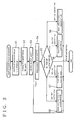
- a vehicle height adjustment device As shown in Fig. 2, a vehicle height adjustment device according to the embodiment is provided with a controller 15 for supply and discharge of working air into which detection signals 9a and 10a from vehicle front and rear height sensors 9 and 10 explained with reference to Fig. 1 are inputted, and from which control signals 13a and 14a are outputted to vehicle front and rear height adjustment valves 13 and 14 in working air systems for front and rear air suspensions, respectively. Further, an input unit 16 is provided to input each of targeted values of a rear end height Hb of and a tilt ⁇ of a vehicle bed 12 (see Fig. 4) to the controller 15.
- the vehicle front height adjustment valve 13 is disposed at a position where working air which is led from an air tank 17 mounted on a transportation vehicle is distributed to each of the front air springs 4 and is constituted as a magnetic valve or similar means which switches flow passages.
- the valve 13 operates such that it selectively connects passages between the air tank 17 and each of the air springs 4 to supply working air to the air springs 4 and selectively opens each of the air springs 4 to the atmosphere to discharge working air from the air springs 4.
- the vehicle rear height adjustment valve 14 is disposed at a position where working air from the air tank 17 is distributed to each of the rear air springs 8, and is constituted as a magnetic valve or similar means which switches flow passages.
- the valve 14 operates such that it selectively connects passages between the air tank 17 and each of the rear air springs 8 to supply working air to the air springs 8 and selectively opens each of the air springs 8 to the atmosphere to discharge working air from the air springs 8.
- Fig. 2 shows the embodiment having the single vehicle front height sensor 9 and the paired vehicle rear height sensors 10.
- the detection signals 10a from both of the vehicle rear height sensors 10 an average of actually measured values is adopted and used for calculations which will be described below.
- the input unit 16 is such that targeted values may be manually inputted with keys, up/down switches or other means; various types of input means may be used.
- the controller 15 is such that, when the targeted values of the rear end height of and the tilt of the vehicle bed 12 are inputted from the input unit 16, it calculates values of the vehicle front and rear heights for achieving the targeted values and controls the vehicle front and rear height adjustment valves 13 and 14 to adjust the vehicle front and rear heights so as to substantially make coincident the actually measured values by the vehicle front and rear height sensors 9 and 10 with the calculated values.
- the input unit 16 is actuated to start the vehicle height adjustment; then, in Step 1, stipulated values s, b, af and ar as shown in Fig. 4 are read.
- s represents a distance between center positions or measurement reference points of the front and rear wheels 1 and 2; b, a distance between the center position or the measurement reference point of the rear wheels 2 and the rear end of the vehicle bed 12; af, a height from the ground to the measurement reference point for the vehicle front height sensor 9; and ar, a height from the ground to the measurement reference point for the vehicle rear height sensors 10.
- Step S2 read are a targeted value for the rear end height Hb of the vehicle bed 12 or height of the platform 11 and a targeted value (positive in the vehicle bed 12 with front-side down, and negative in the vehicle bed 12 with rear-side down) of a tilt ⁇ of the vehicle bed 12 both of which have been manually inputted in the input unit 16.
- Step S4 actually measured values of vehicle front and rear heights hft and hrt of the vehicle bed 12 at a current time (time t from the start) in the position shown with the two-dot chain line in Fig. 4 are read as detection signals 9a and 10a from the vehicle front and rear height sensors 9 and 10, respectively.
- Step S5 the vehicle front and rear heights hf' and hr' calculated in the previous Step S3 are compared with the actually measured vehicle front and rear height hft and hrt read in Step S4, respectively.
- Step S5 If the result of the comparison in Step S5 is hft ⁇ hf' and hrt ⁇ hr', then the procedure proceeds to Step S6 for "front- and rear-side up simultaneously" where the control signals 13a and 14a are outputted to the vehicle front and rear height adjustment valves 13 and 14, respectively, to supply working air to the air springs 4 and 8. Then, the procedure is returned to Step S4 for repetition.
- Step S5 If the result of the comparison in Step S5 is hft ⁇ hf' and hrt> hr', then the procedure proceeds to Step S7 for "front-side up and rear-side down" where the control signals 13a and 14a are outputted to the vehicle front and rear height adjustment valves 13 and 14, respectively, to supply working air to the air spring 4 and to discharge working air from the air springs 8. After that, the procedure is returned to Step S4 for repetition.
- Step S5 If the result of the comparison in Step S5 is hft> hf' and hrt ⁇ hr', the procedure proceeds to Step S8 for "front-side down and rear-side up" where the control signals 13a and 14a are outputted to the vehicle front and rear height adjustment valves 13 and 14, respectively, to discharge working air from the air springs 4 and to supply working air to the air springs 8. After that, the procedure is returned to Step S4 for repetition.
- Step S5 If the result of the comparison in Step S5 is hft> hf' and hrt> hr', then the procedure proceeds to Step S9 for "front- and rear-side down simultaneously" where the control signals 13a and 14a are outputted to the vehicle front and rear height adjustment valves 13 and 14 to discharge working air from the air springs 4 and 8. After that, the procedure is returned again to Step S4 for repetition.
- Step S5 If the result of the comparison in Step S5 is finally hft ⁇ hf ' and hrt ⁇ hr', the vehicle height adjustment is ended. More, the vehicle height adjustment is ended where the following result is obtained:
- the controller 15 described above when used to operate a vehicle height adjustment device, only by inputting targeted values of the rear end height of and the tilt of the vehicle bed 12, the control signals 13a and 14a are outputted to the vehicle front and rear height adjustment valves 13 and 14 from the controller 15 so as to adjust an actual rear end height of and an actual tilt of the vehicle bed 12 into the targeted values.
- supply and discharge of working air to and from the air springs 4 and 8 of the front and rear wheels 1 and 2, respectively are controlled to adjust the vehicle front and rear heights to proper values.
- the rear end height of and the tilt of the vehicle bed 12 are quickly adjusted to desired values.
- the rear end height of and the tilt of the vehicle bed 12 can be quickly adjusted only by simply inputting targeted values. As a result, eliminated is troublesomeness in vehicle height adjustment of the transportation vehicle having the air suspensions for the front and rear wheels 1 and 2. Time required for completing the vehicle height adjustment is drastically shortened in comparison with conventional systems.
Landscapes
- Engineering & Computer Science (AREA)
- Mechanical Engineering (AREA)
- Vehicle Body Suspensions (AREA)
Abstract
Description
- The present invention relates to a vehicle height adjustment device used for a transportation vehicle with air suspensions for front and rear wheels, respectively.
- Conventionally, dominant as a suspension system for transportation vehicles such as trucks for transporting cargoes is a system in which only rear wheels are provided with an air suspension whereas front wheels have a leaf spring suspension. In recent years, however, transportation vehicles having air suspensions for front and rear wheels, respectively, are becoming widespread.
- Fig. 1 shows an example of a transportation vehicle having air suspensions for front and
rear wheels air springs 4 and by arear axle 6 through two sets of pairedair springs 8, the pairedair springs 8 being interconnected longitudinally of the vehicle through asupport beam 7. - The
frame 5 is provided with vehicle front andrear height sensors rear air springs front height sensor 9 serves to measure a distance, as a vehicle front height, from an appropriate reference point on the front axle 3 to theframe 5. The vehiclerear height sensor 10 serves to measure a distance, as a vehicle rear height, from an appropriate reference point on therear axle 6 to theframe 5. - In the transportation vehicle described above having the air suspensions for the front and
rear wheels rear air springs rear sensors vehicle bed 12 can be aligned in height with aplatform 11 when loading and unloading cargoes on to and from thevehicle bed 12 with a rear portion of the vehicle being confronted with theplatform 11. Additionally, thevehicle bed 12 may be tilted longitudinally of the vehicle by adjusting the pressures inside the front andrear air springs vehicle bed 12 is rear-side down for unloading or front-side down for loading, which will facilitate loading and unloading of cargoes in rollaway carriages or baskets. - However, such conventional adjustment system allows wide operational freedom where vehicle front and rear heights are independently adjustable by adjusting the pressures inside the front and
rear air springs vehicle bed 12 into targeted values. - More specifically, the rear end of the
vehicle bed 12 which must be actually aligned in height with theplatform 11 is rearward of a support position of therear air springs 8 so that a measured height by the vehiclerear height sensor 10 differs from an actual height of the rear end of thevehicle bed 12 depending upon the tilt of thebed 12. Therefore, the rear end height of thevehicle bed 12 cannot be maintained to a desired value merely by varying the pressure inside thefront air springs 4 with the pressure inside therear air springs 8 being fixed so as to adjust the tilt of thevehicle bed 12. - For this reason, the rear end of the
vehicle bed 12, which may be temporarily aligned in height with theplatform 11, tends to be readily disaligned with the latter again upon a next operation of adjusts the tilt of thevehicle bed 12. Consequently, it will take tremendous time until the operations are completed to obtain targeted values of both the rear end height of and the tilt of thevehicle bed 12. - In view of the above, an object of the present invention is to provide a vehicle height adjustment device which enables quick and desired adjustment of a rear end height of and a tilt of a vehicle bed only by simply inputting targeted values.
- The invention provides a vehicle height adjustment device used for a transportation vehicle with air suspensions for front and rear wheels, respectively, so as to adjust distances between a front axle and a vehicle body and between a rear axle and the vehicle body by adjustment of pressures inside the air suspensions, characterized in that it comprises a vehicle front height sensor for measuring a vehicle front height defined by the front axle and the vehicle body, a vehicle rear height sensor for measuring a vehicle rear height defined by the rear axle and the vehicle body, a vehicle front height adjustment valve for controlling supply and discharge of working air to and from air springs as the air suspension for the front wheels, a vehicle rear height adjustment valve for controlling supply and discharge of working air to and from air springs as the air suspension for the rear wheels, a controller for outputting control signals to said vehicle front and rear height adjustment valves while checking detection signals from said vehicle front and rear height sensors so that a rear end height of and a tilt of a vehicle bed may be adjusted into targeted values and an input unit for inputting said targeted values to said controller.
- Thus, only inputting of the targeted values for the rear end height of and the tilt of the vehicle bed causes the controller to output the control signals to the vehicle front and rear height adjustment valves so as to adjust an actual rear end height of and an actual tilt of the vehicle bed into the targeted values. As a result, supply and discharge of working air to and from the air springs for the front and rear wheels are controlled to adjust the vehicle front and rear heights to proper values so that a rear end height of and a tilt of the vehicle bed are quickly adjusted as desired.
- It is preferable that, when the targeted values of the rear end height of and the tilt of the vehicle bed are inputted, the controller calculates values of the vehicle front and rear heights for achieving the targeted values and controls the vehicle front and rear height adjustment valves to adjust the vehicle front and rear heights so as to substantially make coincident the actually measured values by the vehicle front and rear height sensors with the calculated values.
- One specific embodiment of the invention will be described with reference to the drawings; in which:
- Fig. 1 is a schematic view showing a conventional transportation vehicle;
- Fig. 2 is a schematic view showing an embodiment of the invention;
- Fig. 3 is a flow chart showing a control procedure of the controller in Fig. 2; and
- Fig. 4 is a view for explanation of adjustment of a rear end height of and a tilt of a vehicle bed.
- Figs. 2 to 4 show an embodiment of the invention in which parts identical to those in Fig. 1 are given the same reference numerals.
-
- As shown in Fig. 2, a vehicle height adjustment device according to the embodiment is provided with a
controller 15 for supply and discharge of working air into which detection signals 9a and 10a from vehicle front andrear height sensors control signals 13a and 14a are outputted to vehicle front and rearheight adjustment valves input unit 16 is provided to input each of targeted values of a rear end height Hb of and a tilt of a vehicle bed 12 (see Fig. 4) to thecontroller 15. - The vehicle front
height adjustment valve 13 is disposed at a position where working air which is led from anair tank 17 mounted on a transportation vehicle is distributed to each of thefront air springs 4 and is constituted as a magnetic valve or similar means which switches flow passages. Thevalve 13 operates such that it selectively connects passages between theair tank 17 and each of theair springs 4 to supply working air to theair springs 4 and selectively opens each of theair springs 4 to the atmosphere to discharge working air from theair springs 4. - Similarly, the vehicle rear
height adjustment valve 14 is disposed at a position where working air from theair tank 17 is distributed to each of therear air springs 8, and is constituted as a magnetic valve or similar means which switches flow passages. Thevalve 14 operates such that it selectively connects passages between theair tank 17 and each of therear air springs 8 to supply working air to theair springs 8 and selectively opens each of theair springs 8 to the atmosphere to discharge working air from theair springs 8. - Fig. 2 shows the embodiment having the single vehicle
front height sensor 9 and the paired vehiclerear height sensors 10. In this arrangement, with respect to thedetection signals 10a from both of the vehiclerear height sensors 10, an average of actually measured values is adopted and used for calculations which will be described below. - The
input unit 16 is such that targeted values may be manually inputted with keys, up/down switches or other means; various types of input means may be used. - The
controller 15 is such that, when the targeted values of the rear end height of and the tilt of thevehicle bed 12 are inputted from theinput unit 16, it calculates values of the vehicle front and rear heights for achieving the targeted values and controls the vehicle front and rearheight adjustment valves rear height sensors - More specifically, as shown in a flow chart for an operation procedure of the
controller 15 in Fig. 3, theinput unit 16 is actuated to start the vehicle height adjustment; then, inStep 1, stipulated values s, b, af and ar as shown in Fig. 4 are read. - Here, s represents a distance between center positions or measurement reference points of the front and
rear wheels rear wheels 2 and the rear end of thevehicle bed 12; af, a height from the ground to the measurement reference point for the vehiclefront height sensor 9; and ar, a height from the ground to the measurement reference point for the vehiclerear height sensors 10. - Subsequently, in Step S2, read are a targeted value for the rear end height Hb of the
vehicle bed 12 or height of theplatform 11 and a targeted value (positive in thevehicle bed 12 with front-side down, and negative in thevehicle bed 12 with rear-side down) of a tilt of thevehicle bed 12 both of which have been manually inputted in theinput unit 16. - Then, in Step S3, calculated are vehicle front and rear heights hf' and hr' for achieving the rear end height Hb of and the tilt of the
vehicle bed 12 by the following formulae: - Further, in Step S4, actually measured values of vehicle front and rear heights hft and hrt of the
vehicle bed 12 at a current time (time t from the start) in the position shown with the two-dot chain line in Fig. 4 are read asdetection signals 9a and 10a from the vehicle front andrear height sensors - And then, in Step S5, the vehicle front and rear heights hf' and hr' calculated in the previous Step S3 are compared with the actually measured vehicle front and rear height hft and hrt read in Step S4, respectively.
- If the result of the comparison in Step S5 is
control signals 13a and 14a are outputted to the vehicle front and rearheight adjustment valves air springs - If the result of the comparison in Step S5 is
control signals 13a and 14a are outputted to the vehicle front and rearheight adjustment valves air spring 4 and to discharge working air from theair springs 8. After that, the procedure is returned to Step S4 for repetition. - If the result of the comparison in Step S5 is
control signals 13a and 14a are outputted to the vehicle front and rearheight adjustment valves air springs 4 and to supply working air to theair springs 8. After that, the procedure is returned to Step S4 for repetition. - If the result of the comparison in Step S5 is
control signals 13a and 14a are outputted to the vehicle front and rearheight adjustment valves air springs - If the result of the comparison in Step S5 is finally
- Therefore, when the
controller 15 described above is used to operate a vehicle height adjustment device, only by inputting targeted values of the rear end height of and the tilt of thevehicle bed 12, thecontrol signals 13a and 14a are outputted to the vehicle front and rearheight adjustment valves controller 15 so as to adjust an actual rear end height of and an actual tilt of thevehicle bed 12 into the targeted values. As a result, supply and discharge of working air to and from theair springs rear wheels vehicle bed 12 are quickly adjusted to desired values. - According to the embodiment described above, the rear end height of and the tilt of the
vehicle bed 12 can be quickly adjusted only by simply inputting targeted values. As a result, eliminated is troublesomeness in vehicle height adjustment of the transportation vehicle having the air suspensions for the front andrear wheels
Claims (2)
- A vehicle height adjustment device used for a transportation vehicle with air suspensions for front and rear wheels (1, 2), respectively, so as to adjust distances between a front axle (3) and a vehicle body (5) and between a rear axle (6) and the vehicle body (5) by adjustment of pressures inside the air suspensions, characterized in that it comprises a vehicle front height sensor (9) for measuring a vehicle front height defined by the front axle (3) and the vehicle body (5), a vehicle rear height sensor (10) for measuring a vehicle rear height defined by the rear axle (6) and the vehicle body (5), a vehicle front height adjustment valve (13) for controlling supply and discharge of working air to and from air springs (4) as the air suspension for the front wheels (1), a vehicle rear height adjustment valve (14) for controlling supply and discharge of working air to and from air springs (8) as the air suspension for the rear wheels (2), a controller (15) for outputting control signals (13a and 14a) to said vehicle front and rear height adjustment valves 13 and 14) while checking detection signals (9a and 10a) from said vehicle front and rear height sensors (9 and 10) so that a rear end height of and a tilt of the vehicle bed may be adjusted into targeted values, and an input unit (16) for inputting said targeted values to said controller (15).
- A device as claimed in Claim 1, wherein, when the targeted values of the rear end height of and the tilt of the vehicle bed are inputted, the controller (15) calculates values of a vehicle front and rear heights for achieving the targeted values and controls the vehicle front and rear height adjustment valves (13 and 14) to adjust the vehicle front and rear heights so as to substantially make coincident actually measured values by the vehicle front and rear height sensors (9 and 10) with the calculated values.
Applications Claiming Priority (2)
| Application Number | Priority Date | Filing Date | Title |
|---|---|---|---|
| JP2001028306A JP3793418B2 (en) | 2001-02-05 | 2001-02-05 | Vehicle height adjustment device |
| JP2001028306 | 2001-02-05 |
Publications (3)
| Publication Number | Publication Date |
|---|---|
| EP1228905A2 true EP1228905A2 (en) | 2002-08-07 |
| EP1228905A3 EP1228905A3 (en) | 2004-01-14 |
| EP1228905B1 EP1228905B1 (en) | 2007-09-12 |
Family
ID=18892828
Family Applications (1)
| Application Number | Title | Priority Date | Filing Date |
|---|---|---|---|
| EP01130787A Expired - Lifetime EP1228905B1 (en) | 2001-02-05 | 2001-12-22 | Vehicle height adjustment device |
Country Status (3)
| Country | Link |
|---|---|
| EP (1) | EP1228905B1 (en) |
| JP (1) | JP3793418B2 (en) |
| DE (1) | DE60130428T2 (en) |
Cited By (22)
| Publication number | Priority date | Publication date | Assignee | Title |
|---|---|---|---|---|
| WO2006071169A1 (en) * | 2004-12-30 | 2006-07-06 | Volvo Lastvagnar Ab | Information based controlling of chassis height of a vehicle |
| EP1844961A1 (en) * | 2006-04-11 | 2007-10-17 | KNORR-BREMSE SYSTEME FÜR NUTZFAHRZEUGE GmbH | Method for the level control of the chassis of a vehicle by adjusting the air mass in the pneumatic spring |
| JP2012158313A (en) * | 2011-02-03 | 2012-08-23 | Hino Motors Ltd | Control device for vehicle air suspension |
| US9045015B2 (en) | 2013-03-07 | 2015-06-02 | Ford Global Technologies, Llc | Laterally tiltable, multitrack vehicle |
| US9090281B2 (en) | 2013-03-07 | 2015-07-28 | Ford Global Technologies, Llc | Laterally tiltable, multitrack vehicle |
| US9145168B2 (en) | 2013-03-07 | 2015-09-29 | Ford Global Technologies, Llc | Laterally tiltable, multitrack vehicle |
| US9248857B2 (en) | 2013-03-07 | 2016-02-02 | Ford Global Technologies, Llc | Laterally tiltable, multitrack vehicle |
| US9283989B2 (en) | 2013-03-07 | 2016-03-15 | Ford Global Technologies, Llc | Laterally tiltable, multitrack vehicle |
| CN105599558A (en) * | 2016-01-15 | 2016-05-25 | 江苏大学 | Electronic control air suspension vehicle body height adjustment and whole vehicle posture combined control method |
| US9821620B2 (en) | 2014-09-01 | 2017-11-21 | Ford Technologies Corporation | Method for operating a tilting running gear and an active tilting running gear for a non-rail-borne vehicle |
| US9845129B2 (en) | 2014-08-29 | 2017-12-19 | Ford Global Technologies, Llc | Stabilizing arrangement for a tilting running gear of a vehicle and tilting running gear |
| US9925843B2 (en) | 2015-02-24 | 2018-03-27 | Ford Global Technologies, Llc | Rear suspension systems for laterally tiltable multitrack vehicles |
| US10023019B2 (en) | 2015-02-24 | 2018-07-17 | Ford Global Technologies, Llc | Rear suspension systems with rotary devices for laterally tiltable multitrack vehicles |
| US10076939B2 (en) | 2014-11-26 | 2018-09-18 | Ford Global Technologies, Llc | Suspension systems for laterally tiltable multitrack vehicles |
| SE541271C2 (en) * | 2014-04-03 | 2019-05-28 | Scania Cv Ab | Method and system for facilitating loading and unloading in a motor vehicle |
| CN110121437A (en) * | 2017-01-26 | 2019-08-13 | 日立汽车系统株式会社 | Suspension system |
| GB2505945B (en) * | 2012-09-17 | 2019-08-28 | Knorr Bremse Systems For Commercial Vehicles Ltd | A trailer automatic level control |
| WO2020040685A1 (en) * | 2018-08-24 | 2020-02-27 | Scania Cv Ab | A method, performed by a control device, for controlling a vehicle height in relation to the road surface and a modularised vehicle comprising such a control device |
| WO2020117111A1 (en) * | 2018-12-07 | 2020-06-11 | Scania Cv Ab | A method, performed by a control device, for controlling a vehicle position in relation to a platform, a control device and a vehicle comprising such a control device |
| CN114475133A (en) * | 2022-02-18 | 2022-05-13 | 岚图汽车科技有限公司 | Vehicle control method, device, equipment and readable storage medium |
| CN115723502A (en) * | 2022-12-07 | 2023-03-03 | 华南理工大学 | Air suspension system vehicle body height adjusting method based on pressure measurement |
| WO2023050095A1 (en) * | 2021-09-28 | 2023-04-06 | 华为技术有限公司 | Solenoid valve assembly, air suspension system, vehicle, control method, and related device |
Families Citing this family (5)
| Publication number | Priority date | Publication date | Assignee | Title |
|---|---|---|---|---|
| DE102011000668C5 (en) * | 2011-02-11 | 2016-03-24 | Haldex Brake Products Gmbh | Method for driver assistance in a docking operation of a commercial vehicle on a ramp |
| JP5890675B2 (en) * | 2011-12-14 | 2016-03-22 | 日野自動車株式会社 | Vehicle air suspension control device |
| CN102616103B (en) * | 2012-04-23 | 2013-09-25 | 扬州万方电子技术有限责任公司 | Mecanum wheel omnidirectional mobile vehicle |
| CN104228510B (en) * | 2014-07-28 | 2016-06-01 | 南车株洲电力机车有限公司 | A kind of pneumatic cushioning regulates supplementary unit |
| DE102017213198B4 (en) * | 2017-07-31 | 2021-08-12 | Knorr-Bremse Systeme für Nutzfahrzeuge GmbH | Method and system for docking a truck or trailer |
Family Cites Families (7)
| Publication number | Priority date | Publication date | Assignee | Title |
|---|---|---|---|---|
| US3765692A (en) * | 1972-06-07 | 1973-10-16 | Ltv Aerospace Corp | Leveling system |
| DE3223140A1 (en) * | 1982-06-22 | 1983-12-22 | Adam Opel AG, 6090 Rüsselsheim | Arrangement for the automatic adjustment of the ground clearance of the body of a vehicle |
| JPS6092912A (en) * | 1983-10-27 | 1985-05-24 | Nippon Denso Co Ltd | Car height control device |
| DE3810386A1 (en) * | 1988-03-26 | 1989-10-05 | Daimler Benz Ag | Device for the arbitrary triggering of the raising and lowering of the vehicle body in relation to at least one vehicle axle on a truck with air suspension |
| GB2317598B (en) * | 1996-09-26 | 2000-10-25 | Multidrive Ltd | Truck |
| SE512146C2 (en) * | 1997-01-24 | 2000-01-31 | Volvo Ab | Device and box for driving position control for an air-sprung vehicle |
| DE19801546A1 (en) * | 1998-01-16 | 1999-07-22 | Koegel Fahrzeugwerke Ag | Bogie angle altering process for multi-axle truck trailer |
-
2001
- 2001-02-05 JP JP2001028306A patent/JP3793418B2/en not_active Expired - Fee Related
- 2001-12-22 DE DE2001630428 patent/DE60130428T2/en not_active Expired - Fee Related
- 2001-12-22 EP EP01130787A patent/EP1228905B1/en not_active Expired - Lifetime
Non-Patent Citations (1)
| Title |
|---|
| None |
Cited By (23)
| Publication number | Priority date | Publication date | Assignee | Title |
|---|---|---|---|---|
| WO2006071169A1 (en) * | 2004-12-30 | 2006-07-06 | Volvo Lastvagnar Ab | Information based controlling of chassis height of a vehicle |
| EP1844961A1 (en) * | 2006-04-11 | 2007-10-17 | KNORR-BREMSE SYSTEME FÜR NUTZFAHRZEUGE GmbH | Method for the level control of the chassis of a vehicle by adjusting the air mass in the pneumatic spring |
| JP2012158313A (en) * | 2011-02-03 | 2012-08-23 | Hino Motors Ltd | Control device for vehicle air suspension |
| GB2505945B (en) * | 2012-09-17 | 2019-08-28 | Knorr Bremse Systems For Commercial Vehicles Ltd | A trailer automatic level control |
| US9045015B2 (en) | 2013-03-07 | 2015-06-02 | Ford Global Technologies, Llc | Laterally tiltable, multitrack vehicle |
| US9090281B2 (en) | 2013-03-07 | 2015-07-28 | Ford Global Technologies, Llc | Laterally tiltable, multitrack vehicle |
| US9145168B2 (en) | 2013-03-07 | 2015-09-29 | Ford Global Technologies, Llc | Laterally tiltable, multitrack vehicle |
| US9248857B2 (en) | 2013-03-07 | 2016-02-02 | Ford Global Technologies, Llc | Laterally tiltable, multitrack vehicle |
| US9283989B2 (en) | 2013-03-07 | 2016-03-15 | Ford Global Technologies, Llc | Laterally tiltable, multitrack vehicle |
| SE541271C2 (en) * | 2014-04-03 | 2019-05-28 | Scania Cv Ab | Method and system for facilitating loading and unloading in a motor vehicle |
| US9845129B2 (en) | 2014-08-29 | 2017-12-19 | Ford Global Technologies, Llc | Stabilizing arrangement for a tilting running gear of a vehicle and tilting running gear |
| US9821620B2 (en) | 2014-09-01 | 2017-11-21 | Ford Technologies Corporation | Method for operating a tilting running gear and an active tilting running gear for a non-rail-borne vehicle |
| US10076939B2 (en) | 2014-11-26 | 2018-09-18 | Ford Global Technologies, Llc | Suspension systems for laterally tiltable multitrack vehicles |
| US9925843B2 (en) | 2015-02-24 | 2018-03-27 | Ford Global Technologies, Llc | Rear suspension systems for laterally tiltable multitrack vehicles |
| US10023019B2 (en) | 2015-02-24 | 2018-07-17 | Ford Global Technologies, Llc | Rear suspension systems with rotary devices for laterally tiltable multitrack vehicles |
| CN105599558A (en) * | 2016-01-15 | 2016-05-25 | 江苏大学 | Electronic control air suspension vehicle body height adjustment and whole vehicle posture combined control method |
| CN110121437A (en) * | 2017-01-26 | 2019-08-13 | 日立汽车系统株式会社 | Suspension system |
| WO2020040685A1 (en) * | 2018-08-24 | 2020-02-27 | Scania Cv Ab | A method, performed by a control device, for controlling a vehicle height in relation to the road surface and a modularised vehicle comprising such a control device |
| WO2020117111A1 (en) * | 2018-12-07 | 2020-06-11 | Scania Cv Ab | A method, performed by a control device, for controlling a vehicle position in relation to a platform, a control device and a vehicle comprising such a control device |
| WO2023050095A1 (en) * | 2021-09-28 | 2023-04-06 | 华为技术有限公司 | Solenoid valve assembly, air suspension system, vehicle, control method, and related device |
| CN114475133A (en) * | 2022-02-18 | 2022-05-13 | 岚图汽车科技有限公司 | Vehicle control method, device, equipment and readable storage medium |
| CN115723502A (en) * | 2022-12-07 | 2023-03-03 | 华南理工大学 | Air suspension system vehicle body height adjusting method based on pressure measurement |
| CN115723502B (en) * | 2022-12-07 | 2024-05-07 | 华南理工大学 | Air suspension system vehicle height adjusting method based on pressure measurement |
Also Published As
| Publication number | Publication date |
|---|---|
| JP2002225530A (en) | 2002-08-14 |
| EP1228905B1 (en) | 2007-09-12 |
| EP1228905A3 (en) | 2004-01-14 |
| DE60130428D1 (en) | 2007-10-25 |
| JP3793418B2 (en) | 2006-07-05 |
| DE60130428T2 (en) | 2008-01-17 |
Similar Documents
| Publication | Publication Date | Title |
|---|---|---|
| EP1228905A2 (en) | Vehicle height adjustment device | |
| US7357397B2 (en) | Method and systems for aligning a stationary vehicle with an artificial horizon | |
| US7744099B2 (en) | Method and system for adjusting a vehicle aligned with an artificial horizon | |
| US8155835B2 (en) | Vehicle chassis height adjustment method and system | |
| US8306696B2 (en) | Method and system for aligning a vehicle with an artificial horizon | |
| US6293562B1 (en) | Method and apparatus for controlling ride height of a wheeled vehicle | |
| US8655577B2 (en) | Device and method for automatically adjusting the horizontal ride level of a utility vehicle | |
| JP4896878B2 (en) | A method for regulating the amount of air in a load-dependent air spring system | |
| US7568713B2 (en) | Air-suspension system for vehicles, having a throttle | |
| EP1484202A2 (en) | Vehicle height adjustment system | |
| US20040026879A1 (en) | Method for controlling a level control system | |
| US20030086077A1 (en) | Optical axis adjusting system for vehicle head lamp | |
| KR100775376B1 (en) | Automatic head lamp leveling system with sensor for tire pressure and method thereof | |
| JP3910766B2 (en) | Vehicle height adjustment device | |
| JP2003170722A (en) | Vehicle height adjusting device for tow car | |
| JP3963627B2 (en) | Air suspension vehicle height adjustment device | |
| JP2001287675A (en) | Adjustment device for air suspension | |
| JP2003063228A (en) | Vehicle height adjusting device | |
| JPS62199510A (en) | Height control device | |
| JP2003025905A (en) | Optical axis adjusting device for vehicular head lamp | |
| JPH0516410U (en) | Vehicle height adjustment device | |
| JP2007230426A (en) | Optical axis adjustment device for truck headlight |
Legal Events
| Date | Code | Title | Description |
|---|---|---|---|
| PUAI | Public reference made under article 153(3) epc to a published international application that has entered the european phase |
Free format text: ORIGINAL CODE: 0009012 |
|
| AK | Designated contracting states |
Kind code of ref document: A2 Designated state(s): AT BE CH CY DE DK ES FI FR GB GR IE IT LI LU MC NL PT SE TR |
|
| AX | Request for extension of the european patent |
Free format text: AL;LT;LV;MK;RO;SI |
|
| PUAL | Search report despatched |
Free format text: ORIGINAL CODE: 0009013 |
|
| AK | Designated contracting states |
Kind code of ref document: A3 Designated state(s): AT BE CH CY DE DK ES FI FR GB GR IE IT LI LU MC NL PT SE TR |
|
| AX | Request for extension of the european patent |
Extension state: AL LT LV MK RO SI |
|
| 17P | Request for examination filed |
Effective date: 20040611 |
|
| AKX | Designation fees paid |
Designated state(s): DE FR GB |
|
| GRAP | Despatch of communication of intention to grant a patent |
Free format text: ORIGINAL CODE: EPIDOSNIGR1 |
|
| GRAS | Grant fee paid |
Free format text: ORIGINAL CODE: EPIDOSNIGR3 |
|
| GRAA | (expected) grant |
Free format text: ORIGINAL CODE: 0009210 |
|
| AK | Designated contracting states |
Kind code of ref document: B1 Designated state(s): DE FR GB |
|
| REG | Reference to a national code |
Ref country code: GB Ref legal event code: FG4D |
|
| REF | Corresponds to: |
Ref document number: 60130428 Country of ref document: DE Date of ref document: 20071025 Kind code of ref document: P |
|
| PLBE | No opposition filed within time limit |
Free format text: ORIGINAL CODE: 0009261 |
|
| STAA | Information on the status of an ep patent application or granted ep patent |
Free format text: STATUS: NO OPPOSITION FILED WITHIN TIME LIMIT |
|
| 26N | No opposition filed |
Effective date: 20080613 |
|
| PG25 | Lapsed in a contracting state [announced via postgrant information from national office to epo] |
Ref country code: FR Free format text: LAPSE BECAUSE OF NON-PAYMENT OF DUE FEES Effective date: 20071231 |
|
| PGFP | Annual fee paid to national office [announced via postgrant information from national office to epo] |
Ref country code: DE Payment date: 20081217 Year of fee payment: 8 |
|
| PGFP | Annual fee paid to national office [announced via postgrant information from national office to epo] |
Ref country code: GB Payment date: 20081217 Year of fee payment: 8 |
|
| GBPC | Gb: european patent ceased through non-payment of renewal fee |
Effective date: 20091222 |
|
| PG25 | Lapsed in a contracting state [announced via postgrant information from national office to epo] |
Ref country code: DE Free format text: LAPSE BECAUSE OF NON-PAYMENT OF DUE FEES Effective date: 20100701 |
|
| PG25 | Lapsed in a contracting state [announced via postgrant information from national office to epo] |
Ref country code: GB Free format text: LAPSE BECAUSE OF NON-PAYMENT OF DUE FEES Effective date: 20091222 |