EP1227549A2 - Connecteur pour carte à puce à revêtement élastique - Google Patents
Connecteur pour carte à puce à revêtement élastique Download PDFInfo
- Publication number
- EP1227549A2 EP1227549A2 EP02001589A EP02001589A EP1227549A2 EP 1227549 A2 EP1227549 A2 EP 1227549A2 EP 02001589 A EP02001589 A EP 02001589A EP 02001589 A EP02001589 A EP 02001589A EP 1227549 A2 EP1227549 A2 EP 1227549A2
- Authority
- EP
- European Patent Office
- Prior art keywords
- card
- portions
- upper face
- frame
- cover
- Prior art date
- Legal status (The legal status is an assumption and is not a legal conclusion. Google has not performed a legal analysis and makes no representation as to the accuracy of the status listed.)
- Withdrawn
Links
Images


Classifications
-
- H—ELECTRICITY
- H01—ELECTRIC ELEMENTS
- H01R—ELECTRICALLY-CONDUCTIVE CONNECTIONS; STRUCTURAL ASSOCIATIONS OF A PLURALITY OF MUTUALLY-INSULATED ELECTRICAL CONNECTING ELEMENTS; COUPLING DEVICES; CURRENT COLLECTORS
- H01R12/00—Structural associations of a plurality of mutually-insulated electrical connecting elements, specially adapted for printed circuits, e.g. printed circuit boards [PCB], flat or ribbon cables, or like generally planar structures, e.g. terminal strips, terminal blocks; Coupling devices specially adapted for printed circuits, flat or ribbon cables, or like generally planar structures; Terminals specially adapted for contact with, or insertion into, printed circuits, flat or ribbon cables, or like generally planar structures
- H01R12/70—Coupling devices
-
- H—ELECTRICITY
- H01—ELECTRIC ELEMENTS
- H01R—ELECTRICALLY-CONDUCTIVE CONNECTIONS; STRUCTURAL ASSOCIATIONS OF A PLURALITY OF MUTUALLY-INSULATED ELECTRICAL CONNECTING ELEMENTS; COUPLING DEVICES; CURRENT COLLECTORS
- H01R13/00—Details of coupling devices of the kinds covered by groups H01R12/70 or H01R24/00 - H01R33/00
- H01R13/02—Contact members
- H01R13/22—Contacts for co-operating by abutting
- H01R13/24—Contacts for co-operating by abutting resilient; resiliently-mounted
- H01R13/2442—Contacts for co-operating by abutting resilient; resiliently-mounted with a single cantilevered beam
Definitions
- the present invention relates to a card connector device to be mounted on equipment in which a card is inserted and removed.
- Fig. 14 illustrates a conventional card connector device.
- This card connector device, or a card connector device 31 is constituted such that a cover 33 made of a metal planar plate is mounted on a frame 32 of a box shape having an open upper face so as to cover the open upper face, an insertion slot 34 is formed at one end portion of the frame 32, a plurality of terminals 35 are supported by the other end portion of the frame 32 with their tip portions being positioned within the frame 32, and rear end portions of the terminals 35 project from the other end portion of the frame 32.
- a hole portion 36 is formed at the cover 33 such that an upper plate of the cover 33 is cut out in a rectangular shape leaving a pair of projection pieces uncut.
- the pair of the projection pieces are bent toward the inside of the open upper face of the frame 32 to form first and second elastic pieces 37 and 38.
- the card connector device 31 is mounted on a circuit board (not shown) and is used with the rear end portions of the plurality of the terminals 35 being soldered to a wiring pattern of the circuit board.
- An upper face of a card (not shown) inserted from the insertion slot 34 is pressed by the first and second elastic pieces 37 and 38 to press contacts provided on a bottom face of the card against the tip portions of the plurality of the terminals 35 as well as against a reference face of the frame. In this way, the contacts of the card and the wiring pattern of the circuit board are electrically connected through the plurality of the terminals 35, so that information is recorded on or reproduced from the card.
- a spring constant of the first and second elastic pieces 37 and 38 has been set at a magnitude that is necessary and sufficient to maintain the connection between the plurality of terminals 35 and the contacts of the card without giving damage to the card. This was achieved with a dimension L1 of the elastic piece adopted long in an insertion direction (direction of arrow A) of the card.
- the hole portion 36 must be made large in size in the insertion direction (direction of arrow A) of the card in order to secure the length dimension L1 of the first and second elastic pieces 37 and 38 long.
- the first and second elastic pieces 37 and 38 cannot press the upper face of the card with a predetermined pressing force.
- An object of the invention is to provide a card connector device which can enhance rigidity of a cover and can press contacts of a card against terminals to maintain the connections between them.
- a card connector device comprises: a frame having an open upper face and an insertion slot formed at one end portion thereof, into which a card is inserted; a metal cover mounted on the frame; and terminals supported by the other end portion of the frame, the terminals being to be connected to contacts provided on a bottom face of the card.
- portions of upper plate of the cover covering the open upper face of the frame are cut and bent toward the inside of the open upper face of the frame to form first and second elastic pieces, which press an upper face of the card to press the contacts in a direction in which the contacts contact with the terminals.
- respective one end portions of the first and second elastic pieces at a side of the insertion slot are supported by the upper plate of the cover, and respective other end portions of the pieces extend, while gradually parting from each other, toward support portions of the terminals of the frame, so as to form a space between the other end portions of the first and the second elastic pieces wider than a space between the one end portions of the first and the second elastic pieces.
- the first and second elastic pieces are disposed on the upper plate of the cover at its one side portion and the other side portion, respectively.
- a center portion of the upper plate of the cover is cut and bent toward the inside of the open upper face of the frame to provide a third elastic piece at the cover.
- the third elastic piece presses a portion on an upper face of the card corresponding to a portion near the contacts to press the contacts against the terminals.
- the third elastic piece comprises a pressing portion, provided at its center portion, for pressing the upper face of the card, and a pair of elastic arm portions continuously formed at both sides of the pressing portion.
- the third elastic piece is supported by the upper plate of the cover at the pair of the elastic arm portions.
- a first cutaway portion and a second cutaway portion are formed on the card at one side portion thereof and the other side portion thereof, respectively, while being displaced from each other in an insertion direction of the card.
- the first and second elastic pieces are arranged at positions, which correspond to the cutaway portions, displaced from each other so that the first and second elastic portions press the both side portions of the upper face of the card while avoiding the first and second cutaway portions.
- the first and second elastic pieces press both side portions, between the portions where the terminals and the contacts contact with each other and the first and the second cutaway portions, of the upper face of the card near the first and the second cutaway portions.
- an indication label is adhered on the upper face of the card, and the first and second elastic pieces press portions other than the indication label on the upper face of the card.
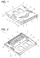
- a card connector device 1 is constituted such that a metal cover 3 is mounted on a box shaped frame 2 having an open upper face so as to cover the open upper face of the frame 2.
- a card 21 used for the card connector device 1 is a type publicly known, and is formed with electronic parts, such as an IC, received in a hard plastic case.
- a taper portion 22 is formed at a corner of its tip end, an indication label 23 in which information such as a product name is written is adhered on its upper face, and a plurality of contacts 24 are arranged side by side at equal space on its bottom face.
- first and second cutaway portions 25 and 25 are provided at one side portion and the other side portion, respectively, at positions displaced from each other in an insertion direction (direction of arrow A) of the card 21.
- a knob 27 for inhibiting writing-in of information is slidably mounted within the first cutaway portion 25.
- the frame 2 is formed from an insulation synthetic resin such as PBT (polybutylene terephthalate) .
- An insertion slot 4 is formed at one end portion of the frame 2, and at the other end of the frame 2, a plurality of terminals 5 are supported by insert molding or press-fitting, with tip end portions of the terminals 5 being positioned within the frame 2.
- Rear end portions of the terminals 5 project from the other end portion of the frame 2.
- Both side portions of the frame 2 serve as a pair of guide portions 6 that guide the card 21 inserted from the insertion slot 4 to the plurality of the terminals 5.
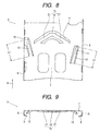
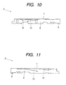
- the cover 3 is formed by bending a planar plate of a metal such as stainless steel, as shown in Figs. 8 to 11.
- the cover 3 comprises an upper plate 7 and a pair of side plates 8 arranged continuously from the upper plate 7.
- Securing pieces 9 are integrally formed at one end portion of the pair of side plates 8, while at the same time both side portions of the upper plate 7 are cut out, leaving respective projection pieces uncut, to form first and second hole portions 10 and 11.
- the pair of projection pieces are bent downwardly to form first and second elastic pieces 12 and 13. Further, the first elastic piece 12 and the second elastic piece 13 are disposed at one side portion and the other side portion of the upper plate 7, respectively.
- space W2 of the other end portions of the first and second elastic pieces 12 and 13 is formed wider.
- the third elastic piece 15 comprises a pressing portion 16 provided at its center portion and a pair of elastic arm portions 17 continuously formed at both sides of the pressing portion 16, and is supported at the upper plate 7 by the pair of elastic arms portions 17.
- the cover 3 is mounted on the frame 2 in such a way that, as shown in Figs. 1 to 5, the securing pieces 9 are secured to a bottom face of the frame 2 and the other end portions of both the side plates 8 are secured to securing projections 18 of the frame 2.
- the first and second elastic pieces 12 and 13 are disposed at positions displaced from each other in an insertion direction (direction of arrow A) of the card 21, and are formed such that, with the respective one end portion at the side of the insertion slot 4 being supported by the upper plate 7 of the cover 3, the respective other end portions extend, while gradually parting from each other, toward support portions of the terminals 5 of the frame 2.
- the card connector device 1 constituted as described above is mounted on a circuit board (not shown) and used with rear end portions of the plurality of terminals 5 being soldered to a wiring pattern of the circuit board.
- the card 21 is led into the frame 2 along the insertion direction (direction of arrow A) of the card 21 as guided by a pair of guide portions 6 of the frame 2. Then, the tip end portion of the card 21 contacts with the other end portion of the first elastic piece 12 while at the same time the taper portion 22 of the card 21 contacts with the other end portion of the second elastic piece 13.
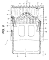
- the first and second elastic pieces 12 and 13 are pushed upward, against their own elasticity, with their one end portions serving as fulcrums. Then, as Fig. 6 shows, the other end portions of the first and second elastic portions 12 and 13 run on the upper face of the card 21.
- the card 21 is further led into the inside of the frame 2 while allowing the other end portions of the first and second elastic pieces 12 and 13 to slide on both the side portions of the upper face of the card 21.
- the tip end portion of the card 21 contacts with the pressing portion 16 of the third elastic piece 15.
- the third elastic piece 15 When the card 21 is further inserted into the inside toward a deepest position in the frame 2, the third elastic piece 15 is pushed upward against its own elasticity with points where the pair of the elastic arm portions 17 and the upper plate 7 of the cover 3 are connected serving as fulcrums. Then the pressing portion 16 of the third elastic piece 15 runs on the upper face of the card 21, and the card 21 is further led to the inside of the frame 2 while allowing the pressing portion 16 of the third elastic piece 15 to slide on the upper face of the card 21.
- Fig. 7 shows, when the card 21 reaches the deepest position in the frame 2, the pressing portion 16 of the third elastic piece 15 positions at a portion on the upper face of the card 21 corresponding to a portion of the contacts 24. Therefore, the third elastic piece 15 presses with its pressing portion 16 the portion on the upper face of the card 21 corresponding to the portion of the contacts 24 to press the contacts 24 against the terminals 5. Also at the same time, the first and second elastic pieces 12 and 13 press portions, located farther toward the insertion slot 4 than the pressing portion 16 of the third elastic piece 15, on the upper face of the card 21.
- first and second elastic pieces 12 and 13 press portions between the portions where the terminals 5 and the contacts 24 contact with each other and the first and second cutaway portions 25 and 26, at both sides of the upper face of the card 21 near the first and the second cutaway portions 25 and 26.
- the contacts 24 are pressed to a direction where they contact with the terminals 5, so that the upper face of the card 21 is pressed by different three points of the first, second, and the third elastic pieces 12, 13, and 15. In this way, each of the contacts 24 is connected to each of the terminals 5.
- the contacts 24 of the card 21 and a wiring pattern of the circuit board are electrically connected through the terminal 5. Consequently, in this state, recording and reproducing signals can be transmitted and received between the card 21 and the circuit board so that recording or reproducing of information to or from the card 21 is carried out.
- the first and second elastic pieces 12 and 13 are formed such that, with their respective one end portion at the side of the insertion slot 4 being supported by the upper plate 7 of the cover 3, their respective other end portions extend, while gradually parting from each other, toward the support portions of the terminals 5 of the frame 2. Consequently, in comparison with space W1 between the one end portions of the first and the second elastic pieces 12 and 13, space W2 between the other end portions of the first and the second elastic pieces 12 and 13 is formed wider. Therefore, as Fig. 8 shows, the sizes of the first and second hole portions 10 and 11 in the insertion direction (direction of arrow A) of the card 21 can be formed small while keeping the length dimension L1 of the first and second elastic pieces 12 and 13 same as that adopted in the prior art. This improves rigidity of the cover 3, making it possible to prevent deformation of the cover 3 under external force such as bending force or torsion.
- the one end portions of the first and second elastic pieces 12 and 13, located at the side of the insertion slot 4 and supported by the upper plate 7 of the cover 3, can be disposed more inward than the other end portions thereof. Therefore, as Fig. 3 shows, a width W3 between the one end portions of first and second elastic pieces 12 and 13 can be set wider than a width W4 between their other end portions. This can enhance elastic limit (strength) of the elastic pieces 12 and 13 themselves as well as that of the cover 3.
- the cover 3 is provided with the third elastic piece 15 for pressing a portion, corresponding to a portion of the contacts 24, of the upper face of the card 21.
- the third elastic piece 15 and the first and second elastic pieces 12 and 13 jointly press the upper face of the card 21 to press the contacts 24 in the direction where they contact with the terminals 5, connections between the contacts 24 and the terminals 5 are secured.
- a length dimension of the pair of elastic arm portions 17 of the third elastic piece 15 can be set long without forming a third hole portion 14 large in the insertion direction (direction of arrow A) of the card 21. Consequently, acting force of the third elastic piece 15 can be set sufficiently large while limiting a magnitude of its spring constant and yet keeping rigidity of the cover 3.
- first and second elastic pieces 12 and 13 are disposed at positions displaced from each other in the insertion direction (direction of arrow A) of the card 21 so that they press the upper face of the card 21 avoiding the cutaway portions 25 and 26. Therefore, the first and second elastic pieces 12 and 13 press both side portions, between portions where the terminals 5 and the contacts 24 contact with each other and the first and second cutaway portions 25 and 26, of the upper face of the card 21 near the first and second cutaway portions 25 and 26.
- the other end portions of first and second elastic pieces 12 and 13 can, in cooperation with the third elastic piece 15, press different three points on the upper face of the card 21 without dropping into the first and second cutaway portions 25 and 26. In this way, the contacts 24 of the card 21 are securely pressed against the terminals 5.
- first and second elastic pieces 12 and 13 press the upper side of the card 21 other than a portion where the indication label 23 is adhered. This prevents peeling off of the indication label 23 or fading of indications on the label 23 caused by sliding on the card 21 of the first and second elastic pieces 12 and 13 at the time of the insertion and removal of the card 21.
- the present invention is realized as the embodiment discussed above, providing effect that will be described below.
- a card connector device comprises: a frame having an open upper face and an insertion slot formed at one end portion thereof, into which a card is inserted; a metal cover mounted on the frame; and terminals supported by the other end portion of the frame, the terminals being to be connected to contacts provided on a bottom face of the card.
- portions of upper plate of the cover covering the open upper face of the frame are cut and bent toward the inside of the open upper face of the frame to form first and second elastic pieces, which press an upper face of the card to press the contacts in a direction in which the contacts contact with the terminals.
- respective one end portions of the first and second elastic pieces at a side of the insertion slot are supported by the upper plate of the cover, and respective other end portions of the pieces extend, while gradually parting from each other, toward support portions of the terminals of the frame, so as to form a space between the other end portions of the first and the second elastic pieces wider than a space between the one end portions of the first and the second elastic pieces.
- the constitution described above enhances rigidity of the cover, prevents deformation of the cover subjected to external force such as bending force or torsion, and presses the contacts of the card against the terminals, without giving any damage to the card, to maintain connections between them.
- first and second elastic pieces are disposed on the upper plate of the cover at its one side portion and the other side portion, respectively.
- a center portion of the upper plate of the cover is cut and bent toward the inside of the open upper face of the frame to provide a third elastic piece at the cover.
- the third elastic piece presses a portion on an upper face of the card corresponding to a portion near the contacts to press the contacts against the terminals. Therefore, connections between the contacts and the terminals can be secured.
- the third elastic piece comprises a pressing portion, provided at its center portion, for pressing the upper face of the card, and a pair of elastic arm portions continuously formed at both sides of the pressing portion.
- the third elastic piece is supported by the upper plate of the cover at the pair of the elastic arm portions. Consequently, the third elastic piece can have sufficiently large acting force while limiting a magnitude of its spring constant and yet keeping its rigidity.
- a first cutaway portion and a second cutaway portion are formed on the card at one side portion thereof and the other side portion thereof, respectively, while being displaced from each other in an insertion direction of the card.
- the first and second elastic pieces are arranged at positions, which correspond to the cutaway portions, displaced from each other so that the first and second elastic portions press the both side portions of the upper face of the card while avoiding the first and second cutaway portions.
- the first and second elastic pieces can securely press the contacts of the card against the terminals without dropping in the first and second cutaway portions .
- first and second elastic pieces press both side portions, between the portions where the terminals and the contacts contact with each other and the first and the second cutaway portions , of the upper face of the card near the first and the second cutaway portions. Therefore, the first and second elastic pieces press, in cooperation with the third elastic piece described above, three different points on the upper face of the card to securely press the contacts of the card against the terminals.
- an indication label is adhered on the upper face of the card, and the first and second elastic pieces press portions other than the indication label on the upper face of the card. This prevents peeling off of the label or fading of indications on the label caused by sliding on the card of the first and second elastic pieces at the time of the insertion and removal of the card 21.
Landscapes
- Coupling Device And Connection With Printed Circuit (AREA)
- Credit Cards Or The Like (AREA)
Applications Claiming Priority (2)
| Application Number | Priority Date | Filing Date | Title |
|---|---|---|---|
| JP2001017857A JP3784646B2 (ja) | 2001-01-26 | 2001-01-26 | カード用コネクタ装置 |
| JP2001017857 | 2001-01-26 |
Publications (2)
| Publication Number | Publication Date |
|---|---|
| EP1227549A2 true EP1227549A2 (fr) | 2002-07-31 |
| EP1227549A3 EP1227549A3 (fr) | 2003-12-10 |
Family
ID=18883971
Family Applications (1)
| Application Number | Title | Priority Date | Filing Date |
|---|---|---|---|
| EP02001589A Withdrawn EP1227549A3 (fr) | 2001-01-26 | 2002-01-23 | Connecteur pour carte à puce à revêtement élastique |
Country Status (6)
| Country | Link |
|---|---|
| US (1) | US20020102882A1 (fr) |
| EP (1) | EP1227549A3 (fr) |
| JP (1) | JP3784646B2 (fr) |
| KR (1) | KR100432205B1 (fr) |
| CN (1) | CN1198367C (fr) |
| TW (1) | TW519784B (fr) |
Families Citing this family (11)
| Publication number | Priority date | Publication date | Assignee | Title |
|---|---|---|---|---|
| JP2003308490A (ja) * | 2002-04-18 | 2003-10-31 | Japan Aviation Electronics Industry Ltd | 電子部品用金属製カバー及びその製造方法 |
| JP2004335172A (ja) * | 2003-05-01 | 2004-11-25 | Hosiden Corp | カードコネクタ |
| JP4141362B2 (ja) * | 2003-09-29 | 2008-08-27 | アルプス電気株式会社 | カードアダプタ |
| TWM280565U (en) * | 2005-03-11 | 2005-11-11 | Hon Hai Prec Ind Co Ltd | Electrical card connector |
| TWM282379U (en) * | 2005-04-29 | 2005-12-01 | Hon Hai Prec Ind Co Ltd | Electrical card connector |
| JP4307419B2 (ja) * | 2005-07-04 | 2009-08-05 | ヒロセ電機株式会社 | カード用コネクタ |
| JP4664170B2 (ja) * | 2005-09-27 | 2011-04-06 | 富士通株式会社 | カードコネクタ装置 |
| TWM308538U (en) * | 2006-09-29 | 2007-03-21 | Tai Sol Electronics Co Ltd | Card connector with small-card guiding function |
| US20100248501A1 (en) * | 2009-03-24 | 2010-09-30 | Chih-Ling Yang | Card Connector |
| CN102709753B (zh) * | 2012-06-08 | 2016-06-08 | 北京盛博协同科技有限责任公司 | 一种cf卡锁紧器 |
| CN105098415B (zh) | 2014-05-07 | 2017-12-05 | 莫仕连接器(成都)有限公司 | 端子座与电子卡连接器 |
Citations (4)
| Publication number | Priority date | Publication date | Assignee | Title |
|---|---|---|---|---|
| JPH07288156A (ja) * | 1994-04-20 | 1995-10-31 | Japan Aviation Electron Ind Ltd | イジェクト機構付きカード用コネクタ |
| JP2001006777A (ja) * | 1999-06-08 | 2001-01-12 | Molex Inc | メモリカード用コネクタ |
| JP2001338729A (ja) * | 2000-05-30 | 2001-12-07 | Alps Electric Co Ltd | カード用コネクタ装置 |
| US20030054694A1 (en) * | 2001-09-07 | 2003-03-20 | Satoshi Takamori | Connector for memory card |
Family Cites Families (4)
| Publication number | Priority date | Publication date | Assignee | Title |
|---|---|---|---|---|
| JP3020020B2 (ja) * | 1995-05-18 | 2000-03-15 | モレックス インコーポレーテッド | カ−ド用コネクタ |
| JP3021369B2 (ja) * | 1996-11-08 | 2000-03-15 | 日本航空電子工業株式会社 | カード用コネクタ |
| US6095868A (en) * | 1997-03-21 | 2000-08-01 | The Whitaker Corporation | Card reader connector having a separable cover |
| JP2000012167A (ja) * | 1998-06-18 | 2000-01-14 | Alps Electric Co Ltd | Icカード用コネクタ |
-
2001
- 2001-01-26 JP JP2001017857A patent/JP3784646B2/ja not_active Expired - Fee Related
- 2001-12-07 TW TW090130433A patent/TW519784B/zh active
-
2002
- 2002-01-02 US US10/038,123 patent/US20020102882A1/en not_active Abandoned
- 2002-01-09 KR KR10-2002-0001236A patent/KR100432205B1/ko not_active IP Right Cessation
- 2002-01-23 EP EP02001589A patent/EP1227549A3/fr not_active Withdrawn
- 2002-01-25 CN CNB021025827A patent/CN1198367C/zh not_active Expired - Fee Related
Patent Citations (4)
| Publication number | Priority date | Publication date | Assignee | Title |
|---|---|---|---|---|
| JPH07288156A (ja) * | 1994-04-20 | 1995-10-31 | Japan Aviation Electron Ind Ltd | イジェクト機構付きカード用コネクタ |
| JP2001006777A (ja) * | 1999-06-08 | 2001-01-12 | Molex Inc | メモリカード用コネクタ |
| JP2001338729A (ja) * | 2000-05-30 | 2001-12-07 | Alps Electric Co Ltd | カード用コネクタ装置 |
| US20030054694A1 (en) * | 2001-09-07 | 2003-03-20 | Satoshi Takamori | Connector for memory card |
Non-Patent Citations (3)
| Title |
|---|
| PATENT ABSTRACTS OF JAPAN vol. 1996, no. 02, 29 February 1996 (1996-02-29) & JP 07 288156 A (JAPAN AVIATION ELECTRON IND LTD), 31 October 1995 (1995-10-31) * |
| PATENT ABSTRACTS OF JAPAN vol. 2000, no. 16, 8 May 2001 (2001-05-08) & JP 2001 006777 A (MOLEX INC), 12 January 2001 (2001-01-12) * |
| PATENT ABSTRACTS OF JAPAN vol. 2002, no. 04, 4 August 2002 (2002-08-04) & JP 2001 338729 A (ALPS ELECTRIC CO LTD), 7 December 2001 (2001-12-07) * |
Also Published As
| Publication number | Publication date |
|---|---|
| KR100432205B1 (ko) | 2004-05-22 |
| KR20020063110A (ko) | 2002-08-01 |
| TW519784B (en) | 2003-02-01 |
| EP1227549A3 (fr) | 2003-12-10 |
| CN1198367C (zh) | 2005-04-20 |
| US20020102882A1 (en) | 2002-08-01 |
| JP3784646B2 (ja) | 2006-06-14 |
| JP2002222392A (ja) | 2002-08-09 |
| CN1367553A (zh) | 2002-09-04 |
Similar Documents
| Publication | Publication Date | Title |
|---|---|---|
| KR100865610B1 (ko) | 카드용 커넥터 | |
| US6261113B1 (en) | Electrical connector having improved arrangement of terminals | |
| US6976880B1 (en) | Card connector | |
| US7059909B1 (en) | Electrical card connector with improved contact structure | |
| US7118420B1 (en) | Dual-slot card connector capable of avoiding erroneous insertion of two cards at once | |
| US7275964B2 (en) | Electrical card connector | |
| WO1998043199A1 (fr) | Connecteur de lecteur de cartes avec couvercle amovible | |
| US6478630B1 (en) | Electrical card connector having polarization mechanism | |
| US7195501B2 (en) | Card connector with ejector | |
| EP1227549A2 (fr) | Connecteur pour carte à puce à revêtement élastique | |
| US20060063422A1 (en) | Electrical card connector with improved detect means | |
| US7326071B1 (en) | Card connector | |
| US20070249202A1 (en) | Card connector | |
| US7247054B2 (en) | Electrical card connector | |
| US7104820B1 (en) | Card connector with reliable signal transmission | |
| US7517237B2 (en) | Electrical card connector | |
| JP4898340B2 (ja) | Icカード用コネクタ | |
| JP3640343B2 (ja) | カードコネクタ | |
| US7389924B2 (en) | Electronic card connector | |
| US20060076410A1 (en) | Card reading device | |
| US7214098B2 (en) | Memory card connector | |
| US20060148322A1 (en) | Memory card connector | |
| JP3897659B2 (ja) | コネクタ | |
| US20080254658A1 (en) | Memory card connector | |
| KR101315675B1 (ko) | 듀얼 소켓 |
Legal Events
| Date | Code | Title | Description |
|---|---|---|---|
| PUAI | Public reference made under article 153(3) epc to a published international application that has entered the european phase |
Free format text: ORIGINAL CODE: 0009012 |
|
| AK | Designated contracting states |
Kind code of ref document: A2 Designated state(s): AT BE CH CY DE DK ES FI FR GB GR IE IT LI LU MC NL PT SE TR |
|
| AX | Request for extension of the european patent |
Free format text: AL;LT;LV;MK;RO;SI |
|
| PUAL | Search report despatched |
Free format text: ORIGINAL CODE: 0009013 |
|
| AK | Designated contracting states |
Kind code of ref document: A3 Designated state(s): AT BE CH CY DE DK ES FI FR GB GR IE IT LI LU MC NL PT SE TR |
|
| AX | Request for extension of the european patent |
Extension state: AL LT LV MK RO SI |
|
| 17P | Request for examination filed |
Effective date: 20031223 |
|
| 17Q | First examination report despatched |
Effective date: 20040308 |
|
| AKX | Designation fees paid |
Designated state(s): DE FI FR GB |
|
| STAA | Information on the status of an ep patent application or granted ep patent |
Free format text: STATUS: THE APPLICATION IS DEEMED TO BE WITHDRAWN |
|
| 18D | Application deemed to be withdrawn |
Effective date: 20040720 |