EP1227211A2 - Device designed to hold the adjustable blades of blinds or the like in predetermined angular positions - Google Patents
Device designed to hold the adjustable blades of blinds or the like in predetermined angular positions Download PDFInfo
- Publication number
- EP1227211A2 EP1227211A2 EP02001662A EP02001662A EP1227211A2 EP 1227211 A2 EP1227211 A2 EP 1227211A2 EP 02001662 A EP02001662 A EP 02001662A EP 02001662 A EP02001662 A EP 02001662A EP 1227211 A2 EP1227211 A2 EP 1227211A2
- Authority
- EP
- European Patent Office
- Prior art keywords
- blades
- blinds
- disk
- angular positions
- predetermined angular
- Prior art date
- Legal status (The legal status is an assumption and is not a legal conclusion. Google has not performed a legal analysis and makes no representation as to the accuracy of the status listed.)
- Granted
Links
- 230000007246 mechanism Effects 0.000 claims abstract description 7
- 230000000087 stabilizing effect Effects 0.000 abstract 1
- 239000000463 material Substances 0.000 description 2
- 238000004836 empirical method Methods 0.000 description 1
- 238000005286 illumination Methods 0.000 description 1
- 239000002184 metal Substances 0.000 description 1
- 238000000034 method Methods 0.000 description 1
- 238000007789 sealing Methods 0.000 description 1
Images

Classifications
-
- E—FIXED CONSTRUCTIONS
- E06—DOORS, WINDOWS, SHUTTERS, OR ROLLER BLINDS IN GENERAL; LADDERS
- E06B—FIXED OR MOVABLE CLOSURES FOR OPENINGS IN BUILDINGS, VEHICLES, FENCES OR LIKE ENCLOSURES IN GENERAL, e.g. DOORS, WINDOWS, BLINDS, GATES
- E06B7/00—Special arrangements or measures in connection with doors or windows
- E06B7/02—Special arrangements or measures in connection with doors or windows for providing ventilation, e.g. through double windows; Arrangement of ventilation roses
- E06B7/08—Louvre doors, windows or grilles
- E06B7/084—Louvre doors, windows or grilles with rotatable lamellae
- E06B7/086—Louvre doors, windows or grilles with rotatable lamellae interconnected for concurrent movement
Definitions
- This patent proposes a device designed to hold the adjustable blades of blinds or the like in predetermined angular positions.
- the device in question compared to known solutions, solves the problem of keeping a certain angular inclination of the blades of blinds which previously were adjusted by empirical methods or by methods, in any case, that were not suited to requirements.
- the invention in question is part of the window and door frame sector and, in particular, part of the sector regarding blinds equipped with adjustable blades such as, for example, the blinds for which the same applicant filed, at a previous date, patents with patent applications No. VR98U000020 and No. VR98U000053.
- Blinds for windows are made using a generally rectangular frame that mounts, internally, a series of crosswise blades or slats placed in an oblique position.
- Blinds which constitute a window closure structure, can be adjusted so that, when open, they permit passage of air and, when closed, prevent light from entering from the outside.
- the solution in question proposes use of a device designed to stabilize the blades of shutters such as blinds in predetermined angular positions, solving all the problems regarding difficulties in keeping the blades at a preset angle since the blades, as is known, can change their inclination due to gusts of air or similar forces and cause bothersome changes in the interior illumination of a room.
- a rotary locator device is proposed in accordance with the main aim of the invention, placed coaxial to at least one of the blades and used to position the blades themselves in preset positions and with increasing inclinations at constant increments.
- the device according to the invention gives a definitive solution to improving angular positioning of the blades of blinds or similar devices and is able to overcome the above-mentioned difficulties.
- a device that locks the blades of blinds or the like in predetermined angular positions, characterized by the fact that it includes at least one basically disk-shaped element with a certain thickness furnished with a series of cavities or seats placed along a ring-shaped band, which disk-shaped element is fastened to the inner side of the frame jamb and by the fact that basically spherical locator elements or the like are combined with and opposed to said basically disk-shaped element and engage in the respective by contrast using spring-type elastic mechanisms or the like positioned in a specific seat machined on at least one of said blades.
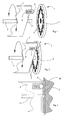
- number 1 indicates the entire complex of the device according to this invention, conceived and made so as to hold the adjustable blades of blinds or the like in predetermined angular positions.
- the device according to the invention basically consists of disk-shaped element 2 the center of which corresponds to the center of shaft 3 of one of blades 4 of the blind on which the device is mounted.
- Disk-shaped element 2 which is fastened to jamb M, has, on its external side, meaning the side facing blades 4 of the frame, a series of cavities or seats 5 placed along a ring-shaped band and at certain predetermined distances one from the other.
- Disk-shaped element 2 is opposed by a basically spherical locator element 6 or similar device which engages in respective slots 5 on the disk, by contrast using spring-type elastic mechanisms 7 or the like, placed in special support 8.
- fixed support 8 is fastened to a seat machined on the side of blade 4, in a position best suited to its object.
- the distance of spherical element 6 and its related support from the center of rotation of shaft 3 will be equal to the radial distance of each of seats 5 of fixed disk 2 from the respective center.
Landscapes
- Engineering & Computer Science (AREA)
- Civil Engineering (AREA)
- Structural Engineering (AREA)
- Blinds (AREA)
- Operating, Guiding And Securing Of Roll- Type Closing Members (AREA)
- Outer Garments And Coats (AREA)
- Curtains And Furnishings For Windows Or Doors (AREA)
Abstract
Description
- This patent proposes a device designed to hold the adjustable blades of blinds or the like in predetermined angular positions.
- It is a device that permits angular positioning of the adjustable blades of shutters such as blinds into predetermined angular positions by using a fixed element placed coaxial to the axis of at least one of the blades themselves on the edge of which there is a locking element put under pressure by a spring.
- The device in question, compared to known solutions, solves the problem of keeping a certain angular inclination of the blades of blinds which previously were adjusted by empirical methods or by methods, in any case, that were not suited to requirements.
- The invention in question is part of the window and door frame sector and, in particular, part of the sector regarding blinds equipped with adjustable blades such as, for example, the blinds for which the same applicant filed, at a previous date, patents with patent applications No. VR98U000020 and No. VR98U000053.
- Blinds for windows are made using a generally rectangular frame that mounts, internally, a series of crosswise blades or slats placed in an oblique position.
- Blinds, which constitute a window closure structure, can be adjusted so that, when open, they permit passage of air and, when closed, prevent light from entering from the outside.
- The patented solutions presented by the same applicant in the above-mentioned applications call for suitable mechanisms that ensure total blackening out of adjustable blades when these are closed, sealing off all those critical areas where light generally penetrates and other mechanisms that create the outer covering of the exterior part of the window frame, composed of covering inserts made of metal and/or plastic materials or other suitable materials that are inserted both on each blade of the blind and on its related supporting frame.
- The solution in question, on the other hand, proposes use of a device designed to stabilize the blades of shutters such as blinds in predetermined angular positions, solving all the problems regarding difficulties in keeping the blades at a preset angle since the blades, as is known, can change their inclination due to gusts of air or similar forces and cause bothersome changes in the interior illumination of a room.
- Use of a rotary locator device is proposed in accordance with the main aim of the invention, placed coaxial to at least one of the blades and used to position the blades themselves in preset positions and with increasing inclinations at constant increments.
- The device according to the invention gives a definitive solution to improving angular positioning of the blades of blinds or similar devices and is able to overcome the above-mentioned difficulties.
- All the specified objects and advantages are achieved, according to the invention, by a device that locks the blades of blinds or the like in predetermined angular positions, characterized by the fact that it includes at least one basically disk-shaped element with a certain thickness furnished with a series of cavities or seats placed along a ring-shaped band, which disk-shaped element is fastened to the inner side of the frame jamb and by the fact that basically spherical locator elements or the like are combined with and opposed to said basically disk-shaped element and engage in the respective by contrast using spring-type elastic mechanisms or the like positioned in a specific seat machined on at least one of said blades.
- Other characteristics and details of the invention can be better understood from the following description, given as a non-exclusive example and which is done in reference to the attached drawings wherein:
- Fig. 1 gives an overall schematic and perspective view of the locator device according to the invention with the contrasting element in a detached position prior to assembly;
- Fig. 2 gives a schematic and perspective view of the device in its working position;
- Fig. 3 schematically illustrates a cross-section of the disk-shaped element fastened to the jamb where it acts as a locator to the contrasting element;
- Fig. 4 gives a schematic and perspective view of one of the possible applications of the device according to the invention, applied to a blind illustrated in an exploded view.
-
- In reference to the attached
figures number 1 indicates the entire complex of the device according to this invention, conceived and made so as to hold the adjustable blades of blinds or the like in predetermined angular positions. - The device according to the invention basically consists of disk-
shaped element 2 the center of which corresponds to the center ofshaft 3 of one ofblades 4 of the blind on which the device is mounted. - Disk-
shaped element 2, which is fastened to jamb M, has, on its external side, meaning theside facing blades 4 of the frame, a series of cavities orseats 5 placed along a ring-shaped band and at certain predetermined distances one from the other. - Disk-
shaped element 2 is opposed by a basicallyspherical locator element 6 or similar device which engages inrespective slots 5 on the disk, by contrast using spring-typeelastic mechanisms 7 or the like, placed inspecial support 8. - In its turn fixed
support 8 is fastened to a seat machined on the side ofblade 4, in a position best suited to its object. - The distance of
spherical element 6 and its related support from the center of rotation ofshaft 3 will be equal to the radial distance of each ofseats 5 of fixeddisk 2 from the respective center. - The operation of the device as described is now evident, providing for
spherical element 6 to engage in one of theslots 5, in the slot that corresponds to the most suitable position of the blade, during rotation ofblade 4 in order to bring it into position. The blade will then be held in position without the possibility of movement caused by gusts of wind or weather up until the next time it is manually adjusted. - It is forecast, as an advantage, that the device as described can be applied not to all the blades but only to some of them, since the others are in any case all connected together by tie-rods or similar devices.
- Another advantage comes from the possibility of making the seats or the notches on the disk-shaped element all on the outer edge of the circular piece or in any other even more suitable position and in this case even
elastic locator element 6 will assume a shape and position suited to the circular piece with which it engages. - A technician in this sector can foresee other possible variations to the device designed to hold the adjustable blades of blinds that is the object of this application, creating solutions that are understood to be included within the scope of protection of the invention, further defined, in its particular characteristics, by the following claims.
Claims (8)
- Device designed to lock the blades of blinds or the like into predetermined angular positions, characterized by the fact that it includes at least one basically disk-shaped element (2) having a certain thickness furnished with a series of cavities or seats (5) placed along a ring-shaped band, which disk-shaped element is fastened to the inner side of the frame jamb and by the fact that basically spherical locator elements or the like are combined with and opposed to said basically disk-shaped element and engage in the related slots by contrast using spring-type elastic mechanisms or the like positioned in a specific seat machined on at least one of said blades.
- Device designed to lock the blades of blinds or the like into predetermined angular positions according to the previous claim, characterized by the fact that the center of said disk-shaped element (2) corresponds to the center of shaft (3) of one of blades (4) of the blind on which the device is mounted.
- Device designed to lock the blades of blinds or the like into predetermined angular positions according to the previous claims, characterized by the fact that said disk-shaped element (2) has, on its external side meaning the side facing blades (4) of the frame, a series of cavities or seats (5) placed along a ring-shaped band and at a certain preset distance one from the other.
- Device designed to lock the blades of blinds or the like into predetermined angular positions according to the previous claims, characterized by the fact that said disk-shaped element (2) is opposed to a basically spherical (6) locator element which engages in the respective slots (5) on the disk, by contrast using spring-type elastic mechanisms (7) or the like placed in a special fixed support (8).
- Device designed to lock the blades of blinds or the like into predetermined angular positions according to the previous claims, characterized by the fact that said fixed support (8), in its turn, will be fastened to a seat machined on the side of blade (4) in a position best suited to its object.
- Device designed to lock the blades of blinds or the like into predetermined angular positions according to the previous claims, characterized by the fact that the distance of spherical element (6) and its related support from the center of rotation of shaft (3) will be equal to the radial distance of each of seats (5) of disk (2) from the respective center.
- Device designed to lock the blades of blinds or the like into predetermined angular positions according to the previous claims, characterized by the fact that it can be applied not to all the blades but only to some of them while the others remain in any case connected together by tie-rods or similar devices.
- Device designed to lock the blades of blinds or the like into predetermined angular positions according to the previous claims, characterized by the fact that the seats or the notches on the disk-shaped element can also be positioned on the outer edge of the circular piece or in any other more suitable position and in this case even the elastic locator element (6) will assume a shape and position suited to the circular piece with which it engages.
Applications Claiming Priority (2)
| Application Number | Priority Date | Filing Date | Title |
|---|---|---|---|
| IT2001VR000005U ITVR20010005U1 (en) | 2001-01-29 | 2001-01-29 | DEVICE SUITABLE FOR HOLDING THE ADJUSTABLE SLATS OF SHUTTERS OR SIMILAR IN PRESET ANGULAR POSITIONS |
| ITVR010005U | 2001-01-29 |
Publications (3)
| Publication Number | Publication Date |
|---|---|
| EP1227211A2 true EP1227211A2 (en) | 2002-07-31 |
| EP1227211A3 EP1227211A3 (en) | 2003-10-01 |
| EP1227211B1 EP1227211B1 (en) | 2010-02-10 |
Family
ID=11461926
Family Applications (1)
| Application Number | Title | Priority Date | Filing Date |
|---|---|---|---|
| EP02001662A Expired - Lifetime EP1227211B1 (en) | 2001-01-29 | 2002-01-24 | Device designed to hold the adjustable blades of blinds or the like in predetermined angular positions |
Country Status (5)
| Country | Link |
|---|---|
| EP (1) | EP1227211B1 (en) |
| AT (1) | ATE457408T1 (en) |
| DE (1) | DE60235288D1 (en) |
| ES (1) | ES2339924T3 (en) |
| IT (1) | ITVR20010005U1 (en) |
Cited By (4)
| Publication number | Priority date | Publication date | Assignee | Title |
|---|---|---|---|---|
| DE20311814U1 (en) * | 2003-07-31 | 2004-12-02 | SCHÜCO International KG | lamella element |
| EP2014862A1 (en) * | 2007-07-11 | 2009-01-14 | Nien Made Enterprise Co., Ltd. | Louver blade positioning device of motorized shutter assembly |
| ES2387424A1 (en) * | 2009-04-13 | 2012-09-21 | Herreria Sierra Sur, S.L. | Antivandalica persiana with hermetic lace (Machine-translation by Google Translate, not legally binding) |
| CN113944418A (en) * | 2021-10-26 | 2022-01-18 | 安徽荣起安防科技有限公司 | Blade contact adjustable zinc steel shutter and installation method thereof |
Citations (1)
| Publication number | Priority date | Publication date | Assignee | Title |
|---|---|---|---|---|
| EP0990762A2 (en) | 1998-10-01 | 2000-04-05 | Di Natale S.r.l. | Shutter with adjustable lamellae and outer covering |
Family Cites Families (2)
| Publication number | Priority date | Publication date | Assignee | Title |
|---|---|---|---|---|
| US684198A (en) * | 1901-02-11 | 1901-10-08 | Jules D Echaux | Shutter-blind fastener. |
| US3189339A (en) * | 1963-12-12 | 1965-06-15 | Siciliann Iginio | Closure operator |
-
2001
- 2001-01-29 IT IT2001VR000005U patent/ITVR20010005U1/en unknown
-
2002
- 2002-01-24 AT AT02001662T patent/ATE457408T1/en not_active IP Right Cessation
- 2002-01-24 ES ES02001662T patent/ES2339924T3/en not_active Expired - Lifetime
- 2002-01-24 DE DE60235288T patent/DE60235288D1/en not_active Expired - Lifetime
- 2002-01-24 EP EP02001662A patent/EP1227211B1/en not_active Expired - Lifetime
Patent Citations (1)
| Publication number | Priority date | Publication date | Assignee | Title |
|---|---|---|---|---|
| EP0990762A2 (en) | 1998-10-01 | 2000-04-05 | Di Natale S.r.l. | Shutter with adjustable lamellae and outer covering |
Cited By (5)
| Publication number | Priority date | Publication date | Assignee | Title |
|---|---|---|---|---|
| DE20311814U1 (en) * | 2003-07-31 | 2004-12-02 | SCHÜCO International KG | lamella element |
| EP2014862A1 (en) * | 2007-07-11 | 2009-01-14 | Nien Made Enterprise Co., Ltd. | Louver blade positioning device of motorized shutter assembly |
| ES2387424A1 (en) * | 2009-04-13 | 2012-09-21 | Herreria Sierra Sur, S.L. | Antivandalica persiana with hermetic lace (Machine-translation by Google Translate, not legally binding) |
| CN113944418A (en) * | 2021-10-26 | 2022-01-18 | 安徽荣起安防科技有限公司 | Blade contact adjustable zinc steel shutter and installation method thereof |
| CN113944418B (en) * | 2021-10-26 | 2023-09-05 | 安徽荣起安防科技有限公司 | Zinc steel shutter with adjustable blade contact and installation method thereof |
Also Published As
| Publication number | Publication date |
|---|---|
| ATE457408T1 (en) | 2010-02-15 |
| EP1227211A3 (en) | 2003-10-01 |
| DE60235288D1 (en) | 2010-03-25 |
| ITVR20010005U1 (en) | 2002-07-29 |
| ES2339924T3 (en) | 2010-05-27 |
| EP1227211B1 (en) | 2010-02-10 |
Similar Documents
| Publication | Publication Date | Title |
|---|---|---|
| US5941021A (en) | Louver-type window and slat therefor | |
| US5471789A (en) | Arched shutter assembly | |
| AU736815B2 (en) | Louvre window clip assembly | |
| CA2415943A1 (en) | Shutter with push/pull control for shutter blades | |
| KR101469946B1 (en) | Natural ventilation apparatus for window | |
| CN108431353B (en) | Hinge assembly | |
| EP1227211B1 (en) | Device designed to hold the adjustable blades of blinds or the like in predetermined angular positions | |
| AU2016312973B2 (en) | Window, shutter or door with adjustable mounting frame | |
| US8365468B2 (en) | Metal bahama style storm shutter | |
| WO2017199188A1 (en) | System for the rotatable coupling of a closing element and stationary support structure | |
| US4694608A (en) | Security bar system for louvered window units | |
| US6988525B2 (en) | Light shelf blind | |
| KR102407495B1 (en) | Window with wind and water proof | |
| JPH0157227B2 (en) | ||
| WO1995025871A1 (en) | Ventilator | |
| JP2002115469A (en) | Rotating louver surface grid | |
| JP3047941U (en) | Sliding shutters | |
| USRE23182E (en) | Adjustable louver shutter or blind | |
| JPH0346159Y2 (en) | ||
| JPH0249354Y2 (en) | ||
| US20240384594A1 (en) | Manual release structure and roll-up door assembly | |
| JP3630405B2 (en) | Adjustment mechanism for raising and lowering windows | |
| WO2012069977A2 (en) | Roller shutter and end cap therefor | |
| JPH0497091A (en) | Louver door | |
| JPS6322289Y2 (en) |
Legal Events
| Date | Code | Title | Description |
|---|---|---|---|
| PUAI | Public reference made under article 153(3) epc to a published international application that has entered the european phase |
Free format text: ORIGINAL CODE: 0009012 |
|
| AK | Designated contracting states |
Kind code of ref document: A2 Designated state(s): AT BE CH CY DE DK ES FI FR GB GR IE IT LI LU MC NL PT SE TR |
|
| AX | Request for extension of the european patent |
Free format text: AL;LT;LV;MK;RO;SI |
|
| PUAL | Search report despatched |
Free format text: ORIGINAL CODE: 0009013 |
|
| AK | Designated contracting states |
Kind code of ref document: A3 Designated state(s): AT BE CH CY DE DK ES FI FR GB GR IE IT LI LU MC NL PT SE TR |
|
| AX | Request for extension of the european patent |
Extension state: AL LT LV MK RO SI |
|
| RIC1 | Information provided on ipc code assigned before grant |
Ipc: 7E 06B 7/086 A Ipc: 7E 06B 7/084 B |
|
| 17P | Request for examination filed |
Effective date: 20040310 |
|
| AKX | Designation fees paid |
Designated state(s): AT BE CH CY DE DK ES FI FR GB GR IE IT LI LU MC NL PT SE TR |
|
| AXX | Extension fees paid |
Extension state: SI Payment date: 20040310 Extension state: AL Payment date: 20040310 Extension state: RO Payment date: 20040310 |
|
| RAP1 | Party data changed (applicant data changed or rights of an application transferred) |
Owner name: DI NATALE S.R.L. |
|
| GRAP | Despatch of communication of intention to grant a patent |
Free format text: ORIGINAL CODE: EPIDOSNIGR1 |
|
| GRAS | Grant fee paid |
Free format text: ORIGINAL CODE: EPIDOSNIGR3 |
|
| GRAA | (expected) grant |
Free format text: ORIGINAL CODE: 0009210 |
|
| AK | Designated contracting states |
Kind code of ref document: B1 Designated state(s): AT BE CH CY DE DK ES FI FR GB GR IE IT LI LU MC NL PT SE TR |
|
| AX | Request for extension of the european patent |
Extension state: AL RO SI |
|
| REG | Reference to a national code |
Ref country code: GB Ref legal event code: FG4D |
|
| REG | Reference to a national code |
Ref country code: CH Ref legal event code: EP |
|
| REG | Reference to a national code |
Ref country code: IE Ref legal event code: FG4D |
|
| REF | Corresponds to: |
Ref document number: 60235288 Country of ref document: DE Date of ref document: 20100325 Kind code of ref document: P |
|
| REG | Reference to a national code |
Ref country code: GR Ref legal event code: EP Ref document number: 20100401009 Country of ref document: GR |
|
| REG | Reference to a national code |
Ref country code: ES Ref legal event code: FG2A Ref document number: 2339924 Country of ref document: ES Kind code of ref document: T3 |
|
| REG | Reference to a national code |
Ref country code: NL Ref legal event code: VDEP Effective date: 20100210 |
|
| PG25 | Lapsed in a contracting state [announced via postgrant information from national office to epo] |
Ref country code: PT Free format text: LAPSE BECAUSE OF FAILURE TO SUBMIT A TRANSLATION OF THE DESCRIPTION OR TO PAY THE FEE WITHIN THE PRESCRIBED TIME-LIMIT Effective date: 20100611 |
|
| PG25 | Lapsed in a contracting state [announced via postgrant information from national office to epo] |
Ref country code: FI Free format text: LAPSE BECAUSE OF FAILURE TO SUBMIT A TRANSLATION OF THE DESCRIPTION OR TO PAY THE FEE WITHIN THE PRESCRIBED TIME-LIMIT Effective date: 20100210 Ref country code: AT Free format text: LAPSE BECAUSE OF FAILURE TO SUBMIT A TRANSLATION OF THE DESCRIPTION OR TO PAY THE FEE WITHIN THE PRESCRIBED TIME-LIMIT Effective date: 20100210 |
|
| PG25 | Lapsed in a contracting state [announced via postgrant information from national office to epo] |
Ref country code: SE Free format text: LAPSE BECAUSE OF FAILURE TO SUBMIT A TRANSLATION OF THE DESCRIPTION OR TO PAY THE FEE WITHIN THE PRESCRIBED TIME-LIMIT Effective date: 20100210 Ref country code: NL Free format text: LAPSE BECAUSE OF FAILURE TO SUBMIT A TRANSLATION OF THE DESCRIPTION OR TO PAY THE FEE WITHIN THE PRESCRIBED TIME-LIMIT Effective date: 20100210 Ref country code: CY Free format text: LAPSE BECAUSE OF FAILURE TO SUBMIT A TRANSLATION OF THE DESCRIPTION OR TO PAY THE FEE WITHIN THE PRESCRIBED TIME-LIMIT Effective date: 20100210 Ref country code: BE Free format text: LAPSE BECAUSE OF FAILURE TO SUBMIT A TRANSLATION OF THE DESCRIPTION OR TO PAY THE FEE WITHIN THE PRESCRIBED TIME-LIMIT Effective date: 20100210 |
|
| PLBE | No opposition filed within time limit |
Free format text: ORIGINAL CODE: 0009261 |
|
| STAA | Information on the status of an ep patent application or granted ep patent |
Free format text: STATUS: NO OPPOSITION FILED WITHIN TIME LIMIT |
|
| 26N | No opposition filed |
Effective date: 20101111 |
|
| PG25 | Lapsed in a contracting state [announced via postgrant information from national office to epo] |
Ref country code: DK Free format text: LAPSE BECAUSE OF FAILURE TO SUBMIT A TRANSLATION OF THE DESCRIPTION OR TO PAY THE FEE WITHIN THE PRESCRIBED TIME-LIMIT Effective date: 20100210 |
|
| PGFP | Annual fee paid to national office [announced via postgrant information from national office to epo] |
Ref country code: GR Payment date: 20110107 Year of fee payment: 10 |
|
| PG25 | Lapsed in a contracting state [announced via postgrant information from national office to epo] |
Ref country code: MC Free format text: LAPSE BECAUSE OF NON-PAYMENT OF DUE FEES Effective date: 20110131 |
|
| REG | Reference to a national code |
Ref country code: CH Ref legal event code: PL |
|
| GBPC | Gb: european patent ceased through non-payment of renewal fee |
Effective date: 20110124 |
|
| REG | Reference to a national code |
Ref country code: IE Ref legal event code: MM4A |
|
| PG25 | Lapsed in a contracting state [announced via postgrant information from national office to epo] |
Ref country code: CH Free format text: LAPSE BECAUSE OF NON-PAYMENT OF DUE FEES Effective date: 20110131 Ref country code: LI Free format text: LAPSE BECAUSE OF NON-PAYMENT OF DUE FEES Effective date: 20110131 |
|
| PG25 | Lapsed in a contracting state [announced via postgrant information from national office to epo] |
Ref country code: GB Free format text: LAPSE BECAUSE OF NON-PAYMENT OF DUE FEES Effective date: 20110124 |
|
| REG | Reference to a national code |
Ref country code: DE Ref legal event code: R119 Ref document number: 60235288 Country of ref document: DE Effective date: 20110802 |
|
| PG25 | Lapsed in a contracting state [announced via postgrant information from national office to epo] |
Ref country code: IE Free format text: LAPSE BECAUSE OF NON-PAYMENT OF DUE FEES Effective date: 20110124 |
|
| PGFP | Annual fee paid to national office [announced via postgrant information from national office to epo] |
Ref country code: FR Payment date: 20120215 Year of fee payment: 11 |
|
| REG | Reference to a national code |
Ref country code: GR Ref legal event code: ML Ref document number: 20100401009 Country of ref document: GR Effective date: 20120802 |
|
| PG25 | Lapsed in a contracting state [announced via postgrant information from national office to epo] |
Ref country code: GR Free format text: LAPSE BECAUSE OF NON-PAYMENT OF DUE FEES Effective date: 20120802 |
|
| PG25 | Lapsed in a contracting state [announced via postgrant information from national office to epo] |
Ref country code: LU Free format text: LAPSE BECAUSE OF NON-PAYMENT OF DUE FEES Effective date: 20110124 |
|
| PG25 | Lapsed in a contracting state [announced via postgrant information from national office to epo] |
Ref country code: DE Free format text: LAPSE BECAUSE OF NON-PAYMENT OF DUE FEES Effective date: 20110802 |
|
| PGFP | Annual fee paid to national office [announced via postgrant information from national office to epo] |
Ref country code: ES Payment date: 20120126 Year of fee payment: 11 |
|
| PG25 | Lapsed in a contracting state [announced via postgrant information from national office to epo] |
Ref country code: TR Free format text: LAPSE BECAUSE OF FAILURE TO SUBMIT A TRANSLATION OF THE DESCRIPTION OR TO PAY THE FEE WITHIN THE PRESCRIBED TIME-LIMIT Effective date: 20100210 |
|
| REG | Reference to a national code |
Ref country code: FR Ref legal event code: ST Effective date: 20130930 |
|
| PG25 | Lapsed in a contracting state [announced via postgrant information from national office to epo] |
Ref country code: FR Free format text: LAPSE BECAUSE OF NON-PAYMENT OF DUE FEES Effective date: 20130131 |
|
| REG | Reference to a national code |
Ref country code: ES Ref legal event code: FD2A Effective date: 20140509 |
|
| PG25 | Lapsed in a contracting state [announced via postgrant information from national office to epo] |
Ref country code: ES Free format text: LAPSE BECAUSE OF NON-PAYMENT OF DUE FEES Effective date: 20130125 |
|
| PGFP | Annual fee paid to national office [announced via postgrant information from national office to epo] |
Ref country code: IT Payment date: 20151223 Year of fee payment: 15 |
|
| PG25 | Lapsed in a contracting state [announced via postgrant information from national office to epo] |
Ref country code: IT Free format text: LAPSE BECAUSE OF NON-PAYMENT OF DUE FEES Effective date: 20170124 |