EP1227035A2 - Einrichtung zum Verbinden beweglicher Teile mit Strukturbauteilen von Flugzeugen od. dgl. - Google Patents
Einrichtung zum Verbinden beweglicher Teile mit Strukturbauteilen von Flugzeugen od. dgl. Download PDFInfo
- Publication number
- EP1227035A2 EP1227035A2 EP01890290A EP01890290A EP1227035A2 EP 1227035 A2 EP1227035 A2 EP 1227035A2 EP 01890290 A EP01890290 A EP 01890290A EP 01890290 A EP01890290 A EP 01890290A EP 1227035 A2 EP1227035 A2 EP 1227035A2
- Authority
- EP
- European Patent Office
- Prior art keywords
- fitting
- aircraft
- movable part
- spoiler
- fittings
- Prior art date
- Legal status (The legal status is an assumption and is not a legal conclusion. Google has not performed a legal analysis and makes no representation as to the accuracy of the status listed.)
- Granted
Links
- 238000005304 joining Methods 0.000 title description 2
- 239000000463 material Substances 0.000 claims abstract description 21
- 239000011347 resin Substances 0.000 claims abstract description 15
- 229920005989 resin Polymers 0.000 claims abstract description 15
- 238000000034 method Methods 0.000 claims abstract description 12
- 239000004033 plastic Substances 0.000 claims abstract description 12
- 239000002131 composite material Substances 0.000 claims abstract description 10
- 229920000049 Carbon (fiber) Polymers 0.000 claims abstract description 7
- 238000001721 transfer moulding Methods 0.000 claims abstract description 7
- 239000004677 Nylon Substances 0.000 claims abstract description 6
- VNWKTOKETHGBQD-UHFFFAOYSA-N methane Chemical compound C VNWKTOKETHGBQD-UHFFFAOYSA-N 0.000 claims abstract description 6
- 229920001778 nylon Polymers 0.000 claims abstract description 6
- 230000002787 reinforcement Effects 0.000 claims abstract 2
- 238000007373 indentation Methods 0.000 claims description 3
- 238000004519 manufacturing process Methods 0.000 description 10
- 239000004744 fabric Substances 0.000 description 6
- 229910052751 metal Inorganic materials 0.000 description 6
- 239000002184 metal Substances 0.000 description 6
- 229910001069 Ti alloy Inorganic materials 0.000 description 4
- 239000000835 fiber Substances 0.000 description 4
- 229910000838 Al alloy Inorganic materials 0.000 description 3
- 238000004026 adhesive bonding Methods 0.000 description 3
- XAGFODPZIPBFFR-UHFFFAOYSA-N aluminium Chemical compound [Al] XAGFODPZIPBFFR-UHFFFAOYSA-N 0.000 description 3
- 238000009745 resin transfer moulding Methods 0.000 description 3
- 230000008646 thermal stress Effects 0.000 description 3
- 239000000853 adhesive Substances 0.000 description 2
- 230000001070 adhesive effect Effects 0.000 description 2
- 238000005516 engineering process Methods 0.000 description 2
- 239000003292 glue Substances 0.000 description 2
- 229910045601 alloy Inorganic materials 0.000 description 1
- 239000000956 alloy Substances 0.000 description 1
- 238000004873 anchoring Methods 0.000 description 1
- 230000015572 biosynthetic process Effects 0.000 description 1
- 239000004917 carbon fiber Substances 0.000 description 1
- 230000000295 complement effect Effects 0.000 description 1
- 238000010276 construction Methods 0.000 description 1
- 238000005260 corrosion Methods 0.000 description 1
- 230000007797 corrosion Effects 0.000 description 1
- 230000000694 effects Effects 0.000 description 1
- 238000005242 forging Methods 0.000 description 1
- 239000000446 fuel Substances 0.000 description 1
- 238000003780 insertion Methods 0.000 description 1
- 230000037431 insertion Effects 0.000 description 1
- 230000007774 longterm Effects 0.000 description 1
- 238000003801 milling Methods 0.000 description 1
- 238000002791 soaking Methods 0.000 description 1
- 238000003860 storage Methods 0.000 description 1
Images





Classifications
-
- B—PERFORMING OPERATIONS; TRANSPORTING
- B64—AIRCRAFT; AVIATION; COSMONAUTICS
- B64C—AEROPLANES; HELICOPTERS
- B64C9/00—Adjustable control surfaces or members, e.g. rudders
- B64C9/02—Mounting or supporting thereof
Definitions
- the invention relates to a device for connecting movable Parts with structural components of aircraft or the like with at least one fitting with at least one bearing.
- the device according to the invention can be used for aircraft, helicopters and other aircraft, and also for other vehicles, such as high-speed ships or high-speed cars.
- the term moving parts includes in particular spoilers, flaps, control surfaces or the like, which are required for controlling the aircraft or the like and for supporting the take-off, landing or driving process.
- the spoilers are spoilers on the rear upper side of the wings of aircraft, which serve on the one hand as brake flaps during landing and on the other hand to support the aileron through asymmetrical use.
- the spoiler creates resistance, which destroys part of the lift.
- structural components includes, in particular, the wings of aircraft or the like. However, the invention can also be used for helicopters in which the wing is formed by a rotor blade which has movable control flaps.
- the moving parts like spoilers, Flaps, control surfaces or the like connected with fittings, which are made of metal, such as aluminum or titanium alloys consist.
- the connection of the fittings with the movable Part is usually done via rivets or detachable Screw connections.
- the fitting contains at least one bearing, via which the movable connection with the structural component, for example, the wing. Because especially at Airplanes on the moving parts and therefore the fittings very much high loads, they must be particularly stable. For this reason, the mostly forged or milled fittings from the materials mentioned are very expensive to manufacture. To reduce fuel costs, one goal is that To reduce the weight of aircraft or the like more and more. By the production of various components as well as spoilers, Flaps, control surfaces and. Like.
- US 4 213 587 A shows an articulated connection between Flaps and structural components, which by a in the structural component anchored and screwed to this fitting and a bearing bolt anchored in the movable part is formed. Due to the different thermal expansion coefficients mentioned above it comes between the fitting and the structural component as well as the fitting and the moving part unwanted tensions. In addition, the anchoring and Connection of the hardware parts with the structural component and the movable Part very complex and have high components Weight on.
- US 5 098 043 A also shows a movable connection between an airfoil and a control surface where a Fitting with the flap over those located in the control surface Structural components connected and rotatable on the bolt Wing is stored.
- the ones already mentioned also occur here Problems with different thermal expansion and weight on.
- a connecting means for connecting a movable flap with a rotor blade of a helicopter is in DE 199 09 257 A1 described, the flap over a drill elastic and rigid rod element connected to the rotor blade or wing is.
- the connection between the bar element and wing or the flap is done with glue and / or screws.
- the drill elastic and rigid member is advantageously made of bonded fiber composite material in one piece manufactured. With the help of such a drill elastic and rigid member elements can only make small movements the flap against the rotor blade can be achieved, which for the use of spoilers or flaps or the like on aircraft would be too small.
- US 4,243,189 A shows a temperature compensated connection between a wing and an elevator, which made of different materials with different coefficients of thermal expansion consists.
- the different expansion values are articulated by an arrangement of each other connected supports compensated.
- the construction is very complex and is not able to solve the problems with the Connections of the supports to the wing or the elevator to prevent.
- EP 532 016 A1 describes a spoiler for the wing of an aircraft, which has fittings that with connected to the spoiler so that the shear forces are minimized can. This connection is made by a special geometric Design of the mounting surface of the fittings and the underside of the spoiler to which the fittings are attached.
- the aim of the present invention is therefore to create a device mentioned above for connecting movable Parts with structural components of aircraft or the like, which the Disadvantages with regard to the thermal expansion of known devices reduce or avoid and also low weight, Resilience as high as possible and as simple as possible Manufacturability shows.
- the facility is said to be good Have long-term properties.
- the object of the invention is achieved in that the at least one fitting made of plastic material, preferably Composite material, manufactured and with the moving parts is glued. On the one hand, this results in a low weight of the Fitting itself and on the other hand a smaller difference between the thermal expansion of the fitting and the thermal expansion of the moving part. Accordingly, the present invention the material interface between plastic and metal from the connection between the moving part and Hardware moved to storage.
- the camp is common designed as a batch or fixed bearing combination and for inclusion of thermal stresses more suitable. As a result of the lesser Differences in thermal expansion are not so demanding the connection between the fitting and the moving part is made, whereby the number of fasteners and thus the weight can be reduced.
- the expensive and expensive manufactured, usually forged or milled Fittings made of almunium and titanium alloys are no longer required.
- plastic components are more resistant to corrosion than Metal components.
- the fitting is made of the same material as the moving part is made. This has both moving part as well Fogging has the same thermal expansion and there are no shear forces on the connecting elements of the fitting with the movable Part.
- the fitting is made of a plastic material after the resin Transfer molding method is made.
- the resin transfer Molding technology brings compared to conventional manufacturing methods using an autoclave in which the prepreg material is cured, advantages.
- US 6 136 236 A a method for the production of components Made of composite material using the resin transfer molding method.
- DE 195 36 675 C1 also describes a device and a Process for the production of large components according to RTM method.
- the fitting advantageously contains carbon fabric Gain.
- the carbon fibers have weight and Strength properties advantages.
- reactive materials such as e.g. Nylon, sewn or woven in, certain properties, such as strength or impact resistance.
- the carbon fabric used can be woven with nylon and after adding the resin, the nylon material is dissolved, which increases the impact resistance.
- the fitting is preferably arranged in this bulge and glued to the moving part. That way you can preferably short fittings connected to moving parts become.
- the adhesive connection can be in places or over the entire Contact surface between the fitting and the movable Part.
- the fitting in a recess in the movable Part arranged and glued to this.
- the recess has a shape complementary to the fitting and encloses thus the fitting arranged therein optimally and thus offers optimal hold.
- the fitting is preferred for an even better hold between an upper and lower cover layer of the movable Partly arranged and preferably glued to them.
- the Cover layers are advantageously made of fiber-reinforced fabric manufactured while the intermediate component Light component, for example a honeycomb core, can be.
- fitting and the moving part are made in one piece are. This is particularly the case with small, moving parts easily possible according to the RTM process, which makes the Fully connecting parts between fitting and moving part not apply, and also the shear forces due to thermal stresses can be eliminated.
- Fig. 1 shows a wing 1 of an aircraft in the view from above.
- spoilers 2 such as flaps 3, Slats 3 '(slats) and control surfaces 4 arranged, which for Control of the aircraft are required.
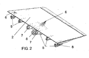
- Fig. 2 shows a perspective view of a movable Part, for example a spoiler 2, which is pivotable with the Wing 1 is connected.
- a movable Part for example a spoiler 2, which is pivotable with the Wing 1 is connected.
- the fittings 5 contain one or several bearings 7 for articulated connection to the wing 1. in addition to the bearings 7 are also articulation points 8 to initiate the Movements of the spoiler 2 provided on the fittings 5.
- the Fittings 5 are usually made of aluminum or titanium alloys manufactured in forging or milling processes. Accordingly their production is complex and expensive.
- FIG. 3 shows the principle of the resin transfer molding (RTM) method, in which the dry fibers 9 in one to be manufactured Object corresponding form 10 are introduced.
- the air can flow out of the mold 10 via corresponding lines 11 be sucked off.
- This can be supplied via a feed line 12 special resin with relatively low viscosity better in penetrate the shape and penetrate the fabric 9.
- Form 10 is then heated to further increase the viscosity of the resin minimize and an undisturbed flow of resin into the mold 10 to ensure. Then the tissue 9 soaking hardens Resin.
- RTM process there are complicated objects easy, quick and relatively inexpensive to manufacture. any with the fabric 9 sewn or woven reactive materials can be easily inserted into the mold and during insertion develop certain properties of the resin. For example can be woven with the fabric 9 nylon. Dissolved by the resin and the impact strength of the manufactured article increase.
- Fig. 4 shows a manufactured by means of the RTM method Fitting 5 made of composite material according to the present invention.
- the fitting 5 is equipped with a bearing 7 and has Connecting surfaces 13 for connection to the movable part, such as. Spoiler 2, on.
- the connection with the moving part done by gluing and possibly additional connecting elements, like screws or rivets.
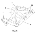
- stiffening structures 14 are provided, which the strength increase the fitting 5 without its weight and volume to enlarge significantly.
- FIG. 5 shows a further embodiment of a Fitting 5 with two bearings 7 and a pivot point 8 and some Stiffening structures 14.
- this can be done simultaneously with the manufacture of the fitting 5 in one operation, preferably according to the RTM method getting produced.
- the properties of the manufactured component easily adjusted, optimized and be tailored to the respective application.
- Changes in the fiber direction of the fabric can, for example mechanical properties can be set or optimized.
- the present invention is characterized by a low weight, high resilience and relatively easy to manufacture out.
- 6 and 7 is a variant of a spoiler, in particular for aircraft, shown with an embedded fitting, wherein the spoiler 2 has an indentation 19 in which the fitting 5 is embedded and fastened by gluing.
- This variant is characterized by a particularly short fitting 5 and results in a relatively low overall weight.
- the glue between the fitting 5 and the spoiler 2 can only on parts of the contact surfaces between the fitting 5 and the spoiler 2 take place or on the entire contact surface.
- FIG. 8 to 10 show a further variant of a spoiler 2, in particular for aircraft, in which the invention Fitting 5 made of plastic material integrated in the spoiler 2 and glued to it.
- Fig. 8 shows a principle Structure of a spoiler 2 made of composite material, comprising a lightweight core 15, for example a honeycomb core with an upper cover layer 16 and a lower cover layer 17, preferably made of impregnated fiber fabrics.
- the Lightweight core 15 has a cutout 18 according to the size of the fitting 5, in which the fitting 5 before joining the Spoiler 2 by gluing the lightweight core 15 to the cover layers 16, 17 is inserted and preferably both with the lightweight core 15 and glued to the cover layers 16, 17 becomes.
- This variant of a wing component stands out due to a deeper fitting 5 and thus a higher weight, withstands higher loads.
Landscapes
- Engineering & Computer Science (AREA)
- Aviation & Aerospace Engineering (AREA)
- Lining Or Joining Of Plastics Or The Like (AREA)
- Connection Of Plates (AREA)
- Moulding By Coating Moulds (AREA)
Abstract
Description
Der Spoiler erzeugt einen Widerstand, wodurch ein Teil des Auftriebs vernichtet wird. Unter den Begriff "Strukturbauteile" fallen insbesondere Tragflächen von Flugzeugen od. dgl. Allerdings ist die Erfindung auch für Hubschrauber, bei welchen der Flügel von einem Rotorblatt gebildet wird, welches bewegliche Steuerungsklappen aufweist, anwendbar.
Claims (10)
- Einrichtung zum Verbinden beweglicher Teile (2, 3, 3', 4) mit Strukturbauteilen (1) von Flugzeugen od. dgl. mit zumindest einem Beschlag (5) mit zumindest einem Lager (7), dadurch gekennzeichnet, dass der zumindest eine Beschlag (5) aus Kunststoffmaterial, vorzugsweise Verbundwerkstoff, hergestellt und mit dem beweglichen Teil (2, 3, 3', 4) verklebt ist.
- Einrichtung nach Anspruch 1, dadurch gekennzeichnet, dass der Beschlag (5) aus dem selben Material wie der bewegliche Teil hergestellt ist.
- Einrichtung nach Anspruch 1 oder 2, dadurch gekennzeichnet, dass weitere Verbindungselemente, wie z.B. Nieten (6) oder Schrauben od. dgl., vorgesehen sind.
- Einrichtung nach einem der Ansprüche 1 bis 3, dadurch gekennzeichnet, dass der Beschlag (5) aus Kunststoffmaterial nach der Resin Transfer Moulding (RTM)-Methode hergestellt ist.
- Einrichtung nach Anspruch 4, dadurch gekennzeichnet, dass der Beschlag (5) Carbongewebe zur Verstärkung enthält.
- Einrichtung nach Anspruch 5, dadurch gekennzeichnet, dass im Carbongewebe reaktive Materialien, wie z.B. Nylon, eingenäht oder eingewebt sind.
- Einrichtung nach einem der Ansprüche 1 bis 6, dadurch gekennzeichnet, dass der Beschlag (5) in einer Einbuchtung (19) des beweglichen Teils (2, 3, 3', 4) eingebettet ist.
- Einrichtung nach einem der Ansprüche 1 bis 6, dadurch gekennzeichnet, dass der Beschlag (5) in einer Ausnehmung (18) des beweglichen Teils (2, 3, 3', 4) angeordnet ist.
- Einrichtung nach Anspruch 8, dadurch gekennzeichnet, dass der Beschlag (5) zwischen einer oberen Deckschicht (16) und einer unteren Deckschicht (17) des beweglichen Teils (2, 3, 3', 4) angeordnet und vorzugsweise mit diesen verklebt ist.
- Einrichtung nach einem der Ansprüche 1 bis 6, dadurch gekennzeichnet, dass der Beschlag (5) und der bewegliche Teil (2, 3, 3', 4) einstückig hergestellt ist.
Priority Applications (3)
| Application Number | Priority Date | Filing Date | Title |
|---|---|---|---|
| AT01890290T ATE284346T1 (de) | 2001-01-26 | 2001-10-10 | Einrichtung zum verbinden beweglicher teile mit strukturbauteilen von flugzeugen od. dgl. |
| CA002367981A CA2367981C (en) | 2001-01-26 | 2002-01-14 | Device for connecting movable parts with structural elements of airplanes or the like |
| US10/053,666 US8453972B2 (en) | 2001-01-26 | 2002-01-24 | Device for connecting movable parts with structural elements of airplanes or the like |
Applications Claiming Priority (2)
| Application Number | Priority Date | Filing Date | Title |
|---|---|---|---|
| AT1312001 | 2001-01-26 | ||
| AT1312001A AT409482B (de) | 2001-01-26 | 2001-01-26 | Einrichtung zum verbinden beweglicher teile mit strukturbauteilen von flugzeugen od. dgl. |
Publications (3)
| Publication Number | Publication Date |
|---|---|
| EP1227035A2 true EP1227035A2 (de) | 2002-07-31 |
| EP1227035A3 EP1227035A3 (de) | 2003-11-26 |
| EP1227035B1 EP1227035B1 (de) | 2004-12-08 |
Family
ID=3636850
Family Applications (1)
| Application Number | Title | Priority Date | Filing Date |
|---|---|---|---|
| EP20010890290 Expired - Lifetime EP1227035B1 (de) | 2001-01-26 | 2001-10-10 | Einrichtung zum Verbinden beweglicher Teile mit Strukturbauteilen von Flugzeugen od. dgl. |
Country Status (4)
| Country | Link |
|---|---|
| EP (1) | EP1227035B1 (de) |
| AT (1) | AT409482B (de) |
| DE (1) | DE50104758D1 (de) |
| ES (1) | ES2233596T3 (de) |
Cited By (6)
| Publication number | Priority date | Publication date | Assignee | Title |
|---|---|---|---|---|
| US7631840B2 (en) | 2004-10-08 | 2009-12-15 | Patria Aerostructures Oy | Pivoting panel for aircraft, and composite support piece |
| EP2862798A3 (de) * | 2013-08-29 | 2015-07-15 | Airbus Operations Limited | Flugzeugstruktur und Herstellungsverfahren |
| EP2930102A1 (de) * | 2014-04-08 | 2015-10-14 | Marc Arnold | Flugsteuerungaugmentationssystem und -verfahren für flugzeug mit hoher streckung |
| WO2016023056A1 (de) * | 2014-08-11 | 2016-02-18 | Facc Ag | Steuerflächenelement für ein flugzeug |
| WO2016168879A1 (de) | 2015-04-24 | 2016-10-27 | Facc Ag | Steuerflächenelement |
| CN114476021A (zh) * | 2022-01-22 | 2022-05-13 | 威海光威复合材料股份有限公司 | 机翼与舵体的连接方法 |
Citations (7)
| Publication number | Priority date | Publication date | Assignee | Title |
|---|---|---|---|---|
| US4213587A (en) | 1978-12-04 | 1980-07-22 | The Boeing Company | Hinge arrangement for control surfaces |
| US4243189A (en) | 1978-12-18 | 1981-01-06 | The Boeing Company | Temperature stabilized linkage |
| US5098043A (en) | 1990-02-27 | 1992-03-24 | Grumman Aerospace Corporation | Integrated power hinge actuator |
| EP0532016A1 (de) | 1991-09-13 | 1993-03-17 | Grumman Aerospace Corporation | Faserverstärkte Steuerfläche mit fokussierter Belastung |
| DE19536675C1 (de) | 1995-09-30 | 1997-02-20 | Deutsche Forsch Luft Raumfahrt | Vorrichtung und Verfahren zur Herstellung von großflächigen Bauelementen nach dem RTM-Verfahren |
| DE19909257A1 (de) | 1999-03-03 | 2000-09-14 | Eurocopter Deutschland | Verbindungsmittel zum Verbinden einer beweglichen Klappe mit einem Flügel eines Luftfahrzeuges |
| US6136236A (en) | 1996-06-19 | 2000-10-24 | Aerospatiale Societe Nationale Industrielle | Method for manufacturing composite material pieces by resin transfer moulding |
Family Cites Families (4)
| Publication number | Priority date | Publication date | Assignee | Title |
|---|---|---|---|---|
| US3140066A (en) * | 1962-12-04 | 1964-07-07 | North American Aviation Inc | Multiple pivot mounting means |
| FR2718707B1 (fr) * | 1994-04-18 | 1996-07-12 | Aerospatiale | Dispositif de protection d'une charnière de gouverne, notamment pour aéronef. |
| US6270039B1 (en) * | 1999-10-12 | 2001-08-07 | Patria Finavicomp Oy | Hinge for movable control surfaces in an aircraft and a connecting piece to be used with such a hinge |
| FR2815933B1 (fr) * | 2000-10-26 | 2003-01-24 | Eads Airbus Sa | Organe et dispositif de transmission d'efforts radiaux entre des regions centrale et d'extremite de cet organe |
-
2001
- 2001-01-26 AT AT1312001A patent/AT409482B/de active
- 2001-10-10 EP EP20010890290 patent/EP1227035B1/de not_active Expired - Lifetime
- 2001-10-10 DE DE50104758T patent/DE50104758D1/de not_active Expired - Lifetime
- 2001-10-10 ES ES01890290T patent/ES2233596T3/es not_active Expired - Lifetime
Patent Citations (7)
| Publication number | Priority date | Publication date | Assignee | Title |
|---|---|---|---|---|
| US4213587A (en) | 1978-12-04 | 1980-07-22 | The Boeing Company | Hinge arrangement for control surfaces |
| US4243189A (en) | 1978-12-18 | 1981-01-06 | The Boeing Company | Temperature stabilized linkage |
| US5098043A (en) | 1990-02-27 | 1992-03-24 | Grumman Aerospace Corporation | Integrated power hinge actuator |
| EP0532016A1 (de) | 1991-09-13 | 1993-03-17 | Grumman Aerospace Corporation | Faserverstärkte Steuerfläche mit fokussierter Belastung |
| DE19536675C1 (de) | 1995-09-30 | 1997-02-20 | Deutsche Forsch Luft Raumfahrt | Vorrichtung und Verfahren zur Herstellung von großflächigen Bauelementen nach dem RTM-Verfahren |
| US6136236A (en) | 1996-06-19 | 2000-10-24 | Aerospatiale Societe Nationale Industrielle | Method for manufacturing composite material pieces by resin transfer moulding |
| DE19909257A1 (de) | 1999-03-03 | 2000-09-14 | Eurocopter Deutschland | Verbindungsmittel zum Verbinden einer beweglichen Klappe mit einem Flügel eines Luftfahrzeuges |
Cited By (9)
| Publication number | Priority date | Publication date | Assignee | Title |
|---|---|---|---|---|
| US7631840B2 (en) | 2004-10-08 | 2009-12-15 | Patria Aerostructures Oy | Pivoting panel for aircraft, and composite support piece |
| EP2862798A3 (de) * | 2013-08-29 | 2015-07-15 | Airbus Operations Limited | Flugzeugstruktur und Herstellungsverfahren |
| EP2930102A1 (de) * | 2014-04-08 | 2015-10-14 | Marc Arnold | Flugsteuerungaugmentationssystem und -verfahren für flugzeug mit hoher streckung |
| WO2016023056A1 (de) * | 2014-08-11 | 2016-02-18 | Facc Ag | Steuerflächenelement für ein flugzeug |
| US10518866B2 (en) | 2014-08-11 | 2019-12-31 | Facc Ag | Control surface element for an airplane |
| WO2016168879A1 (de) | 2015-04-24 | 2016-10-27 | Facc Ag | Steuerflächenelement |
| US10562607B2 (en) | 2015-04-24 | 2020-02-18 | Facc Ag | Control surface element |
| AT517198B1 (de) * | 2015-04-24 | 2021-12-15 | Facc Ag | Steuerflächenelement für ein Flugzeug |
| CN114476021A (zh) * | 2022-01-22 | 2022-05-13 | 威海光威复合材料股份有限公司 | 机翼与舵体的连接方法 |
Also Published As
| Publication number | Publication date |
|---|---|
| ES2233596T3 (es) | 2005-06-16 |
| EP1227035A3 (de) | 2003-11-26 |
| AT409482B (de) | 2002-08-26 |
| DE50104758D1 (de) | 2005-01-13 |
| EP1227035B1 (de) | 2004-12-08 |
| ATA1312001A (de) | 2002-01-15 |
Similar Documents
| Publication | Publication Date | Title |
|---|---|---|
| DE69837640T2 (de) | Äusseres Gondelverkleidungspanel einer Triebwerkgondel mit integrierten Führungsschienenverkleidungen und Verfahren zu dessen Herstellung | |
| EP2032830B1 (de) | Führungsträger für triebwerksverkleidungen | |
| DE68914567T2 (de) | Hybride Hubschrauberrotornabenplatte. | |
| EP2257467B1 (de) | Querstossverbindung zwischen zwei rumpsektionen sowie verfahren zur herstellung derselben | |
| DE69206541T2 (de) | Faserverstärkte Steuerfläche mit fokussierter Belastung. | |
| DE102012000564B4 (de) | Urformwerkzeug und Verfahren für die Fertigung eines aus faserverstärktem Kunststoff bestehenden aerodynamisch geformten Luftfahrzeugbauteils | |
| EP2162354B1 (de) | Rotorblatt für ein drehflügelflugzeug | |
| EP2280867B1 (de) | Lateral-kopplungsvorrichtung zum halten und führen zumindest eines aerodynamischen körpers gegenüber dem hauptflügel eines flugzeugs, tragflügel und flugzeug mit einer solchen lateral-kopplungsvorrichtung | |
| DE2109692C3 (de) | Flügelkasten für Luftfahrzeuge in Verbundbauweise | |
| EP3078587A1 (de) | Flügelkörper | |
| EP4010178B1 (de) | Verfahren zum reparieren eines faserverbundbauteils | |
| DE69504089T2 (de) | Dämpfer lager haltevorrichtung für einen lagerfreien hubschrauberrotor | |
| EP1393893B1 (de) | Leichtbaustruktur aus metallischen Schichtwerkstoffen | |
| EP2170696A2 (de) | Profil mit wenigstens einem hohlprofilabschnitt | |
| EP1438230B1 (de) | Trag- bzw. führungsvorrichtung für flugzeugkomponenten | |
| DE102010013370B4 (de) | eingegangenWandbauteil für ein Luftfahrzeug | |
| DE102011017460A1 (de) | Faserverbundbauteil, Flügelspitzenverlängerung und Flugzeug mit einem Faserverbundteil | |
| DE60011923T2 (de) | Scharnier für flugzeugsteuerflächen und verbindungselement zur verwendung mit einem solchen scharnier | |
| DE102008047793B4 (de) | Lasteinleitungselement | |
| DE102014106930B4 (de) | Lasttragendes Verkleidungselement für eine Klappenverstellmechanik und Flugzeug mit einem solchen Verkleidungselement | |
| EP1227035B1 (de) | Einrichtung zum Verbinden beweglicher Teile mit Strukturbauteilen von Flugzeugen od. dgl. | |
| DE102014102117B4 (de) | Verfahren und Verbindungsanordnung zum Verbinden eines Strömungskörper-Bauelementes mit einem oder mehreren Bauteilen | |
| DE102011084433A1 (de) | Komponente, Verstärkungsbauteil, Strukturanordnung, Luft- oder Raumfahrzeug sowie Verfahren | |
| EP0732262A2 (de) | Strukturelement | |
| EP2048077A2 (de) | Auftriebsklappenträgersystem |
Legal Events
| Date | Code | Title | Description |
|---|---|---|---|
| PUAI | Public reference made under article 153(3) epc to a published international application that has entered the european phase |
Free format text: ORIGINAL CODE: 0009012 |
|
| AK | Designated contracting states |
Kind code of ref document: A2 Designated state(s): AT BE CH CY DE DK ES FI FR GB GR IE IT LI LU MC NL PT SE TR |
|
| AX | Request for extension of the european patent |
Free format text: AL;LT;LV;MK;RO;SI |
|
| PUAL | Search report despatched |
Free format text: ORIGINAL CODE: 0009013 |
|
| AK | Designated contracting states |
Kind code of ref document: A3 Designated state(s): AT BE CH CY DE DK ES FI FR GB GR IE IT LI LU MC NL PT SE TR |
|
| AX | Request for extension of the european patent |
Extension state: AL LT LV MK RO SI |
|
| 17P | Request for examination filed |
Effective date: 20031114 |
|
| GRAP | Despatch of communication of intention to grant a patent |
Free format text: ORIGINAL CODE: EPIDOSNIGR1 |
|
| GRAS | Grant fee paid |
Free format text: ORIGINAL CODE: EPIDOSNIGR3 |
|
| AKX | Designation fees paid |
Designated state(s): AT BE CH CY DE DK ES FI FR GB GR IE IT LI LU MC NL PT SE TR |
|
| GRAA | (expected) grant |
Free format text: ORIGINAL CODE: 0009210 |
|
| AK | Designated contracting states |
Kind code of ref document: B1 Designated state(s): AT BE CH CY DE DK ES FI FR GB GR IE IT LI LU MC NL PT SE TR |
|
| PG25 | Lapsed in a contracting state [announced via postgrant information from national office to epo] |
Ref country code: IE Free format text: LAPSE BECAUSE OF FAILURE TO SUBMIT A TRANSLATION OF THE DESCRIPTION OR TO PAY THE FEE WITHIN THE PRESCRIBED TIME-LIMIT Effective date: 20041208 Ref country code: NL Free format text: LAPSE BECAUSE OF FAILURE TO SUBMIT A TRANSLATION OF THE DESCRIPTION OR TO PAY THE FEE WITHIN THE PRESCRIBED TIME-LIMIT Effective date: 20041208 Ref country code: TR Free format text: LAPSE BECAUSE OF FAILURE TO SUBMIT A TRANSLATION OF THE DESCRIPTION OR TO PAY THE FEE WITHIN THE PRESCRIBED TIME-LIMIT Effective date: 20041208 |
|
| REG | Reference to a national code |
Ref country code: GB Ref legal event code: FG4D Free format text: NOT ENGLISH |
|
| REG | Reference to a national code |
Ref country code: CH Ref legal event code: EP |
|
| REG | Reference to a national code |
Ref country code: IE Ref legal event code: FG4D Free format text: GERMAN |
|
| REF | Corresponds to: |
Ref document number: 50104758 Country of ref document: DE Date of ref document: 20050113 Kind code of ref document: P |
|
| PG25 | Lapsed in a contracting state [announced via postgrant information from national office to epo] |
Ref country code: SE Free format text: LAPSE BECAUSE OF FAILURE TO SUBMIT A TRANSLATION OF THE DESCRIPTION OR TO PAY THE FEE WITHIN THE PRESCRIBED TIME-LIMIT Effective date: 20050308 Ref country code: GR Free format text: LAPSE BECAUSE OF FAILURE TO SUBMIT A TRANSLATION OF THE DESCRIPTION OR TO PAY THE FEE WITHIN THE PRESCRIBED TIME-LIMIT Effective date: 20050308 Ref country code: DK Free format text: LAPSE BECAUSE OF FAILURE TO SUBMIT A TRANSLATION OF THE DESCRIPTION OR TO PAY THE FEE WITHIN THE PRESCRIBED TIME-LIMIT Effective date: 20050308 |
|
| GBT | Gb: translation of ep patent filed (gb section 77(6)(a)/1977) |
Effective date: 20050211 |
|
| NLV1 | Nl: lapsed or annulled due to failure to fulfill the requirements of art. 29p and 29m of the patents act | ||
| REG | Reference to a national code |
Ref country code: ES Ref legal event code: FG2A Ref document number: 2233596 Country of ref document: ES Kind code of ref document: T3 |
|
| REG | Reference to a national code |
Ref country code: IE Ref legal event code: FD4D |
|
| ET | Fr: translation filed | ||
| PG25 | Lapsed in a contracting state [announced via postgrant information from national office to epo] |
Ref country code: CY Free format text: LAPSE BECAUSE OF FAILURE TO SUBMIT A TRANSLATION OF THE DESCRIPTION OR TO PAY THE FEE WITHIN THE PRESCRIBED TIME-LIMIT Effective date: 20051010 |
|
| PLBE | No opposition filed within time limit |
Free format text: ORIGINAL CODE: 0009261 |
|
| STAA | Information on the status of an ep patent application or granted ep patent |
Free format text: STATUS: NO OPPOSITION FILED WITHIN TIME LIMIT |
|
| PG25 | Lapsed in a contracting state [announced via postgrant information from national office to epo] |
Ref country code: LU Free format text: LAPSE BECAUSE OF NON-PAYMENT OF DUE FEES Effective date: 20051031 Ref country code: MC Free format text: LAPSE BECAUSE OF NON-PAYMENT OF DUE FEES Effective date: 20051031 Ref country code: BE Free format text: LAPSE BECAUSE OF NON-PAYMENT OF DUE FEES Effective date: 20051031 Ref country code: CH Free format text: LAPSE BECAUSE OF NON-PAYMENT OF DUE FEES Effective date: 20051031 Ref country code: LI Free format text: LAPSE BECAUSE OF NON-PAYMENT OF DUE FEES Effective date: 20051031 |
|
| 26N | No opposition filed |
Effective date: 20050909 |
|
| REG | Reference to a national code |
Ref country code: CH Ref legal event code: PL |
|
| BERE | Be: lapsed |
Owner name: *FISCHER ADVANCED COMPOSITE COMPONENTS A.G. Effective date: 20051031 |
|
| PG25 | Lapsed in a contracting state [announced via postgrant information from national office to epo] |
Ref country code: PT Free format text: LAPSE BECAUSE OF NON-PAYMENT OF DUE FEES Effective date: 20050508 |
|
| REG | Reference to a national code |
Ref country code: FR Ref legal event code: CD |
|
| REG | Reference to a national code |
Ref country code: FR Ref legal event code: PLFP Year of fee payment: 15 |
|
| REG | Reference to a national code |
Ref country code: FR Ref legal event code: PLFP Year of fee payment: 16 |
|
| REG | Reference to a national code |
Ref country code: FR Ref legal event code: PLFP Year of fee payment: 17 |
|
| REG | Reference to a national code |
Ref country code: FR Ref legal event code: PLFP Year of fee payment: 18 |
|
| PGFP | Annual fee paid to national office [announced via postgrant information from national office to epo] |
Ref country code: FR Payment date: 20190919 Year of fee payment: 19 Ref country code: FI Payment date: 20190927 Year of fee payment: 19 |
|
| PGFP | Annual fee paid to national office [announced via postgrant information from national office to epo] |
Ref country code: GB Payment date: 20190913 Year of fee payment: 19 |
|
| PGFP | Annual fee paid to national office [announced via postgrant information from national office to epo] |
Ref country code: DE Payment date: 20191030 Year of fee payment: 19 |
|
| PGFP | Annual fee paid to national office [announced via postgrant information from national office to epo] |
Ref country code: IT Payment date: 20191017 Year of fee payment: 19 Ref country code: ES Payment date: 20191108 Year of fee payment: 19 |
|
| PGFP | Annual fee paid to national office [announced via postgrant information from national office to epo] |
Ref country code: AT Payment date: 20191009 Year of fee payment: 19 |
|
| REG | Reference to a national code |
Ref country code: DE Ref legal event code: R119 Ref document number: 50104758 Country of ref document: DE |
|
| REG | Reference to a national code |
Ref country code: FI Ref legal event code: MAE |
|
| REG | Reference to a national code |
Ref country code: AT Ref legal event code: MM01 Ref document number: 284346 Country of ref document: AT Kind code of ref document: T Effective date: 20201010 |
|
| GBPC | Gb: european patent ceased through non-payment of renewal fee |
Effective date: 20201010 |
|
| PG25 | Lapsed in a contracting state [announced via postgrant information from national office to epo] |
Ref country code: DE Free format text: LAPSE BECAUSE OF NON-PAYMENT OF DUE FEES Effective date: 20210501 Ref country code: FR Free format text: LAPSE BECAUSE OF NON-PAYMENT OF DUE FEES Effective date: 20201031 Ref country code: FI Free format text: LAPSE BECAUSE OF NON-PAYMENT OF DUE FEES Effective date: 20201010 |
|
| PG25 | Lapsed in a contracting state [announced via postgrant information from national office to epo] |
Ref country code: GB Free format text: LAPSE BECAUSE OF NON-PAYMENT OF DUE FEES Effective date: 20201010 Ref country code: AT Free format text: LAPSE BECAUSE OF NON-PAYMENT OF DUE FEES Effective date: 20201010 |
|
| PG25 | Lapsed in a contracting state [announced via postgrant information from national office to epo] |
Ref country code: IT Free format text: LAPSE BECAUSE OF NON-PAYMENT OF DUE FEES Effective date: 20201010 |
|
| REG | Reference to a national code |
Ref country code: ES Ref legal event code: FD2A Effective date: 20220127 |
|
| PG25 | Lapsed in a contracting state [announced via postgrant information from national office to epo] |
Ref country code: ES Free format text: LAPSE BECAUSE OF NON-PAYMENT OF DUE FEES Effective date: 20201011 |