EP1226581B1 - Procede et dispositif d'initialisation de disques optiques numeriques - Google Patents
Procede et dispositif d'initialisation de disques optiques numeriques Download PDFInfo
- Publication number
- EP1226581B1 EP1226581B1 EP00974642A EP00974642A EP1226581B1 EP 1226581 B1 EP1226581 B1 EP 1226581B1 EP 00974642 A EP00974642 A EP 00974642A EP 00974642 A EP00974642 A EP 00974642A EP 1226581 B1 EP1226581 B1 EP 1226581B1
- Authority
- EP
- European Patent Office
- Prior art keywords
- disc
- rotation
- optical
- assembly
- sub
- Prior art date
- Legal status (The legal status is an assumption and is not a legal conclusion. Google has not performed a legal analysis and makes no representation as to the accuracy of the status listed.)
- Expired - Lifetime
Links
Images


Classifications
-
- G—PHYSICS
- G11—INFORMATION STORAGE
- G11B—INFORMATION STORAGE BASED ON RELATIVE MOVEMENT BETWEEN RECORD CARRIER AND TRANSDUCER
- G11B7/00—Recording or reproducing by optical means, e.g. recording using a thermal beam of optical radiation by modifying optical properties or the physical structure, reproducing using an optical beam at lower power by sensing optical properties; Record carriers therefor
- G11B7/24—Record carriers characterised by shape, structure or physical properties, or by the selection of the material
- G11B7/26—Apparatus or processes specially adapted for the manufacture of record carriers
Definitions
- the present invention relates to the field of writing equipment data on optical media such as optical discs.
- certain digital optical discs of the type rewritable e.g. CD-RW - ReWritable-, DVD-RW, or DVD-RAM
- use to enable re-registration function on the same supports a phase change effect of a sensitive material (typically tellurium-based alloy), and which passes from a crystalline state to an amorphous state and reciprocally under the effect of temperature, these two states being stable at ambient temperature
- the disc generally consisting of a pancake polycarbonate covered with dielectric layers, of said sensitive material, another layer of dielectric, and finally a metallic reflector aluminized.
- the state of the sensitive layer is amorphous.
- initializer equipment which heats the sensitive layer of the disc locally, while avoiding melting the substrate polycarbonate.
- the heating of the sensitive layer is carried out at a temperature of the order of 150 ° C. to 200 ° C. (depending on the composition and the nature of the sensitive layer).
- the length of the light brush is approximately 100 ⁇ m, for 1 ⁇ m of width, with a heating power of 1 W distributed over this area.
- the sweep tracks are done with an overlap in length.
- the current tendency is then to seek to reduce the cycle time of manufacturing around 3 or 4 seconds, and in parallel that of the initializers around 15 at 20 seconds. It is then a question of increasing the thermal power focused on an area of the sensitive layer of the disc, without destroying or damage the polycarbonate substrate, which does not support a local temperature above 80 ° C.
- Focusing is done automatically by a device called autofocus.
- This device encounters difficulties in focusing on the disc because the surface of the disc to be initialized is not very reflective. Time necessary to focus is important, which increases the time of the initialization cycle.
- the autofocus devices used are moreover generally unreliable and lack robustness.
- the present invention therefore intends to remedy these drawbacks by proposing a new method and the device for initializing disks associated rewritable digital optics, whose cycle time is around 15 to 20 seconds.
- the invention also aims at a simpler device for setting artwork.
- the invention aims under a first aspect an initialization method of rewritable digital optical disc of the type comprising a layer sensitive to two stable states and such as local heating produced by projection of a light spot allows the passage from one state to the other state so reversible, the light power and the speed of passage of the stain light corresponding to an optical light density allowing transition from one state to another of the sensitive layer.
- the light spot has a depth of field greater than 25 ⁇ m and a width between 5 and 20 ⁇ m for a length between about 50 and 500 ⁇ m.
- Using a bright spot with a depth of field high solves the problems related to focusing. Thanks to that high depth of field, focus does not need to be particularly refined and can therefore be carried out very quickly or be only adjusted from time to time.
- This device is, according to the invention, characterized in that the sub optical assembly comprises at least one laser diode controlled by a laser control device, and an optical focusing system, in that each laser diode has a wavelength substantially between 700 and 1000 nanometers, and in that the device uses a heating beam having a small aperture angle, a depth of field greater than 25 ⁇ m at the sensitive layer, and a width of between 5 and 20 ⁇ m for a length between 50 and 500 ⁇ m approximately.
- the optical sub-assembly achieves two different magnifications on the two axes of the laser brush created by the diode laser at least one. These enlargements will preferably be independent of each other.
- the optical sub-assembly includes for example two cylindrical lenses allowing to work on both axes separately, the lens working on the lateral axis (dimension of the brush generally 1 ⁇ m), providing magnification between 6 and 15 approximately, and the lens working on the longitudinal axis ensuring a focusing of this axis in the same place as the lateral axis, with a magnification less than or equal to 1.
- the sub-assembly optic includes an aspherical collimator to obtain a beam parallel, and two cylindrical lenses in the Gauss conditions in the center, or corrected for use in larger openings.
- the rotation sub-assembly placed under the disc to be initialized comprises for example a suction system which keeps the disc in place according to a precise plan by means of a flexible porous sheet intended for take place between a plate and the disc to be initialized, a rotation motor, a rotation encoder, a rotation control device regulating the operation of the rotation motor, and the disk suction system comprises for example means for carrying out this aspiration between rotation motor bearings.
- the advance sub-assembly of the heating beam on the surface of the disc may include a means of rotation, of axis parallel to the axis of rotation of the disc, and on the axis of which is secured an optical beam comprising the optical sub-assembly.
- the laser diode at least least one used is a diode with a large emission aperture which occurs in the form of a bar with a power greater than 2 W, preferably greater than 3 W.
- the device according to the invention can comprise several lasers.
- these emit for example each one in direction a polarization splitter cube to combine the two sources light to obtain a bright spot of greater power.
- the laser source 5 chosen for the present device is of length between 750 and 1000 nanometers, with higher power at 3 Watts. It is of the classic type in this area and is presented under shape of a bar 5.
- the focusing optical system is defined by the width of the brush that we want to obtain on the surface of the optical disc, as well as by depth of field.
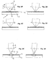
- FIG. 2A shows a thin brush of the type which we have just describe, properly focused on the surface of the disc.
- the laser brush 8 being emitted from the upper part in the figure, a focusing lens 9 focuses this paintbrush on a heated surface 10 (shown here by an elongated rectangle) of the sensitive layer 11 of the disc 2, with an opening angle 12.
- Figure 2B illustrates an angular positioning error of the brush laser, for example a few tens of milliradians.
- a mismatch angular causes an identical angular offset of the heated surface 10, which now overlaps both the substrate 13 and the layer of protection 14.
- this angular offset does not lead to a very significant overlap, and therefore remains appreciably without consequence on the quality of the optical disc.
- the device of the present invention voluntarily uses a small opening angle 12, with a related depth of markedly increased field, here of the order of 100 ⁇ m against 1 ⁇ m in art prior.
- the brush focused on the disc is then much larger dimension, with a width close to 5 to 20 ⁇ m, against 1 ⁇ m conventionally, and therefore a lower power density at equal laser diode power.
- the method which has been chosen by the present device concerning the initialization of disk 2 is to use a light power important and to pass a large light spot at great depth of field at high speed on the surface of the disc 2, whereas in the art anterior a narrow light spot passes at low speed on this surface.
- the following principle is then applied here: the law expressing the temperature of a point on the surface of the disc as a function of time is kept if we grow similarly the width of the light spot and the speed of movement of the spot, at constant optical density.
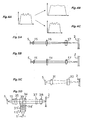
- FIG. 4A illustrates a power profile of a laser strip 5.
- the abscissa is used to represent a position on the bar concerned while the ordinate axis indicates a power.
- Figure 4B illustrates the power profile transmitted over the heated surface by a device conforming to the invention while FIG. 4C illustrates a power profile transmitted over the heated surface of a prior art initializer.
- the optical sub-assembly 1 for this purpose comprises two lenses cylindrical allowing to work on the two axes separately.
- the lens working on the lateral axis should provide a magnification of about 6. Knowing that the depth of field is proportional to the square of the magnification, compared to a magnification of 1 as generally used in the prior art, the depth of field is 36 times greater and therefore 36 times less sensitive focusing for an optical system as described here in relation to a classic optical system. In such a case, taking into account the tolerances of the initializer, the device can be used without using specific focusing system.
- the focal length of the cylindrical lens must simply allow to focus this axis in the same place that the lateral axis, with a magnification less than 1, is 0.25 in the example given.
- This type of system is known to those skilled in the art as "4f" system.
- the optical path first comprises a collimator aspherical 15 making it possible to obtain a parallel beam, and two lenses cylindrical 16, 17 under Gauss conditions in the center for quality beam optics, or corrected for use in larger apertures important.
- FIGS. 5A and 5B show the same device, once in view of above and the other time in side view.
- the types and dimensions of the lenses chosen are deduced from the power and size of the light brush.
- optical sub-assembly is simple and therefore economical and of realization and maintenance facilitated.
- Figure 5C shows an embodiment using only two cylindrical lenses. These are calculated aspherical lenses and obtained by molding.
- a first lens 31 acts on the magnification of the length of the laser strip while the second lens 32 acts on the enlargement of the width of this bar.
- the lenses used here are specific lenses whose shape is calculated in according to the characteristics which one wishes to obtain.
- the fourth embodiment illustrated in Figure 5D shows a light source comprising two laser strips 5 and 5 '. These two bars are identical and conform to the description given above with reference to the bar 5. They are arranged at right angles so that the beams emitted converge to a point of intersection 33.
- a cube separating polarization 34 At the point of intersection 33 is a cube separating polarization 34. Between each strip 5, resp. 5 ', and the separator cube polarization 34 there is each time a collimator 15, resp. 15 ', as well that a cylindrical lens 35, resp. 35 '. Between the 35 'lens and the separator cube polarization 34 is also a half-wave plate 36 '. This 36 'blade allows to modify the polarization of the light emitted by the 5 'strip.
- the cube polarization splitter 34 as shown in Figure 5D, has a plane inclined at 45 ° with respect to the beams emitted by the bars 5 and 5 '.
- This plan inclined is transparent for the beams coming from the strip 5 and is reflective for those from the 5 'bar and which, thanks to the blade half-wave 36 ', a polarization different from 90 ° relative to these.
- cube outlet 34 the two beams coming from the two bars 5 and 5 'come so overlap.
- a servo fast current a few microseconds
- light control a few milliseconds
- CAV Constant Angular Velocity
- a slow servo whose sensor is reflectivity
- the rotation sub-assembly 4 placed under the disc 2 to be initialized it includes a suction system 18, which keeps the disc 2 in place and according to a precise plan, a rotation motor 19 and an encoder of rotation 20.
- a rotation control device 21 regulates the operation of the rotation motor 19. It is then possible to initialize the disk 2 with a constant initialization linear speed.
- the device rotation control 21 is sometimes called CLV (Constant Linear Velocity or constant linear speed).
- suction system 18 of the disc 2 is produced through the bearings 22 of the rotation motor 19, by means 23 of classic type not detailed.
- the disc 2 intended to be initialized is then placed on a surface insulating and flexible which ensures contact over its entire surface, and is vacuumed by its center.
- This device which has no grooves, makes it possible to avoid local deformation of the disc and hard spots (thermal insulation).
- a flexible porous sheet is placed between the suction plate and the disc to achieve uniform suction over the entire surface of the disc.
- the rotation motor 19 of the disc 2 is a brushless type motor, likely to reach high speeds (of the order of 50,000 revolutions per minute). We also choose an engine capable of reaching 25,000 revolutions per minute in less than 1 second, so as to further reduce the cycle time complete initialization.
- the disc to be initialized 2 being placed on the rotation sub-assembly 4, whose purpose is to allow its maintenance in a predetermined plan, and its adequate rotation, the optical sub-assembly 1 scans the sensitive surface of said disc 2 by a laser brush with the characteristics described above. This subset optics is then slaved for its positioning to the sub-assembly in advance 3, which will now be described.
- the feed sub-assembly 3 mainly comprises a motor for rotation 24 of the feed, and a feed control device 25.
- This advance system is special in that, unlike conventional devices, the advance function is not performed by a motor linear, but by a rotation motor 24 (see Figure 6).
- This choice of a rotation motor 24 is dictated by two considerations: on the one hand, it is insensitive to shocks in translation, and, on the other hand, this rotation allows to store the optical beam 26 (which contains the sub-assembly optical 1) faster to release the disc 2, than in the case of an engine of translation. This results in a saving of time over the complete initialization cycle.
- Figure 6 shows a very schematic top view of the system in rotation according to the invention.
- the rotation motor for the advance 24 allows a passage between a high position 26A of the beam optic 26, (allowing it to be stored and the deposit or removal of the disc 2 to initialize), a tangent position 26B corresponding to the radius outside of disc 2, for which the operation actually begins initialization, and an internal position 26C, which corresponds to the most radius inside the disc to initialize.
- the trajectory of the focused brush is illustrated by the circular arc 28.
- the device may include an error correction system positioning due to the curved trajectory, of conventional type, not detailed here.
- This rotary feed system provides excellent angular precision between the axis 29 of rotation of the disc 2 and the axis 30 of rotation of the optical beam 26. This point is particularly interesting in the since this device does not use a servo control device focusing the light brush on the surface of the disc 2.
- the device includes a control algorithm making it possible to reach rapid accesses, of the order of a few g (1g worth approximately 9.81 m / s 2 ) at the level of the load, so as to reduce the cycle time.
- a classic type position and speed control is also integrated into the device.
- the advance system could use in this example not limiting nested spirals which allow to take advantage of both the outward journey and the return of the optical beam 26 to carry out the initialization of the disk 2.
- the system described above also allows the use of lasers multiples which are in the form of bars aligned one behind the others but with a space between each bar.
- the man of the trade by combining devices as described above, can achieve an initialization device which describes several spirals during the initialization of the disk. By enslavement of the advance, it is then possible to achieve a gain significant time during initialization.
- the feed rotation motor 24 is of a similar type to the disc rotation 19 (i.e. a brushless electric motor capable of reach 25,000 revolutions per minute in less than 1 second).
- the feed motor 24 and the motor 19 of disk 2 are synchronized.
- the feed rotation motor 24 is slave of rotation motor 19 of disk 2.
- the control algorithm used has the same advantages in this case as a gear drive, in particular the rigor in the reduction ratio.
Landscapes
- Engineering & Computer Science (AREA)
- Manufacturing & Machinery (AREA)
- Optical Recording Or Reproduction (AREA)
- Manufacturing Optical Record Carriers (AREA)
- Optical Head (AREA)
Description
- chargement d'un disque, et dépôt du disque sur un plateau aspirant d'un sous-ensemble rotation d'un dispositif d'initialisation,
- aspiration du disque pour le maintenir en position,
- mise en rotation du disque par un moteur de rotation, pour atteindre une vitesse de défilement de piste comprise entre 3 m/s et 50 m/s,
- mise en place d'un système optique comprenant au moins une diode laser au dessus du disque, au niveau du rayon extérieur, par mise en marche simultanée d'un moteur de rotation d'avance,
- mise en marche de la diode laser, et initialisation du disque pendant une durée fonction de la puissance optique choisie,
- retour du système optique dans sa position initiale de repos, et arrêt de la rotation du disque par arrêt du moteur de rotation,
- légère surpression pour libérer le disque du plateau du sous-ensemble de rotation,
- déchargement du disque.
- un sous-ensemble optique créant un faisceau de chauffage local de la couche sensible du disque, adapté à permettre le changement de phase du matériau constituant ladite couche sensible et l'initialisation effective du disque,
- un sous-ensemble d'avance du faisceau de chauffage sur la surface du disque, et
- un sous-ensemble de rotation qui vient entraíner le disque en rotation lors de la phase d'initialisation.
- un sous-ensemble optique 1, comprenant une diode laser 5 commandée par un dispositif de commande laser 6 et un système optique de focalisation 7, qui vient juste au dessus de la surface d'un disque 2, par exemple de type DVD ou CD, et qui comporte un dispositif de chauffage local de surface permettant le changement de phase du matériau et l'initialisation effective du disque,
- un sous-ensemble d'avance 3 régulant la position de la diode laser 5 relativement au rayon du disque 2,
- un sous-ensemble de rotation 4, qui vient entraíner le disque 2 en rotation lors de la phase d'initialisation.
- détection des phases des pôles du rotor,
- recherche de la fonction de transfert,
- détection des butées de mouvement (limites 26A, 26B, 26C de mouvement angulaire de la poutre optique 26 lors de l'initialisation du disque 2),
- asservissement en position angulaire de la poutre optique 26,
- asservissement du mouvement de la poutre optique 26 à la rotation du disque à vitesse très faible,
- accès rapide à un point quelconque du disque 2 avec une accélération de 10g au niveau de la charge (c'est à dire au niveau du pinceau lumineux parallèle à l'axe de rotation du disque 2).
- chargement du disque 2, par prise du disque par un robot (non détaillé car classique) et dépôt du disque 2 sur le plateau aspirant du sous-ensemble rotation 4 de l'initialiseur,
- aspiration du disque 2 pour le maintenir en position,
- mise en rotation du disque 2 par le moteur de rotation 19, pour atteindre une vitesse de défilement de piste comprise entre 3 m/s et 50 m/s,
- mise en place du système optique 26 au dessus du disque 2 (au niveau du rayon extérieur, position tangentielle 26B), par mise en marche simultanée du moteur de rotation d'avance 24,
- mise en marche de la diode laser 5, et initialisation du disque 2 pendant une durée fonction de la puissance optique choisie (la durée d'initialisation étant sensiblement inversement proportionnelle à la puissance optique transmise au disque), ici réduit d'un facteur 16,
- retour du système optique 26 dans sa position initiale de repos 26A, et arrêt de la rotation du disque 2 par arrêt du moteur de rotation 19,
- légère surpression pour libérer le disque 2 du plateau du sous-ensemble de rotation 4,
- déchargement du disque 2 par le robot.
Claims (11)
- Procédé d'initialisation de disque optique numérique réinscriptible (2) du type comportant une couche sensible (11) à deux états stables et tel qu'un chauffage local réalisé par projection d'une tache lumineuse permet le passage d'un état à l'autre état de façon réversible, la puissance lumineuse et la vitesse de passage de la tache lumineuse correspondant à une densité lumineuse optique permettant de réaliser le passage d'un état à l'autre de la couche sensible,
caractérisé en ce que la tache lumineuse présente une profondeur de champ supérieure à 25 µm et une largeur comprise entre 5 et 20 µm pour une longueur comprise entre 50 et 500 µm environ. - Procédé d'initialisation d'un disque optique selon la revendication 1, caractérisé en ce qu'il comporte les étapes suivantes :chargement d'un disque (2), et dépôt du disque (2) sur un plateau aspirant d'un sous-ensemble rotation (4) d'un dispositif d'initialisation,aspiration du disque (2) pour le maintenir en position,mise en rotation du disque (2) par un moteur de rotation (19), pour atteindre une vitesse de défilement de piste comprise entre 3 m/s et 50 m/s,mise en place d'un système optique (26) comprenant au moins une diode laser (5) au dessus du disque (2), au niveau du rayon extérieur (26B), par mise en marche simultanée d'un moteur de rotation d'avance (24),mise en marche de la diode laser (5), et initialisation du disque (2) pendant une durée fonction de la puissance optique choisie,retour du système optique (26) dans sa position initiale de repos (26A), et arrêt de la rotation du disque (2) par arrêt du moteur de rotation (19),légère surpression pour libérer le disque (2) du plateau du sous-ensemble de rotation (4),déchargement du disque (2).
- Dispositif d'initialisation d'un disque optique numérique réinscriptible (2) présentant une couche sensible (11 ), comportant :caractérisé en ce que le sous ensemble optique (1) comprend au moins une diode laser (5) commandée par un dispositif de commande laser (6), et un système optique de focalisation (7),un sous-ensemble optique (1) créant un faisceau de chauffage local de la couche sensible (11) du disque (2), adapté à permettre le changement de phase du matériau constituant ladite couche sensible (11) et l'initialisation effective du disque (2),un sous-ensemble d'avance (3) du faisceau de chauffage sur la surface du disque (2), etun sous-ensemble de rotation (4) qui vient entraíner le disque (2) en rotation lors de la phase d'initialisation,
en ce que chaque diode laser (5) est de longueur d'onde sensiblement comprise entre 700 et 1000 nanomètres, et
en ce que le dispositif utilise un faisceau de chauffage ayant un angle d'ouverture (12) faible, une profondeur de champ supérieure à 25 µm au niveau de la couche sensible (11), et une largeur comprise entre 5 et 20 µm pour une longueur comprise entre 50 et 500 µm environ. - Dispositif selon la revendication 3, caractérisé en ce que le sous-ensemble optique (1) un réalise deux grandissements différents sur les deux axes du pinceau laser créé par la diode laser (5) au nombre d'au moins une.
- Dispositif selon la revendication 4, caractérisé en ce que le sous-ensemble optique (1) comporte deux lentilles cylindriques permettant de travailler sur les deux axes séparément, la lentille travaillant sur l'axe latéral, fournissant un grandissement compris entre 6 et 15 environ, et la lentille travaillant sur l'axe longitudinal assurant une focalisation de cet axe au même endroit que l'axe latéral, avec un grandissement inférieur ou égal à 1.
- Dispositif selon la revendication 5, caractérisé en ce que le sous-ensemble optique (1) comprend un collimateur asphérique (15) permettant d'obtenir un faisceau parallèle, et deux lentilles cylindriques (16, 17) dans les conditions de Gauss au centre, ou corrigées pour être utilisées dans des ouvertures plus importantes.
- Dispositif selon l'une quelconque des revendications 3 à 6, caractérisé en ce que le dispositif de commande laser (6), qui contrôle la diode (5) au nombre d'au moins une, réalise un asservissement laser sur trois niveaux :1/ asservissement rapide en courant (quelques microsecondes) de type analogique pour l'élimination du bruit,2/ asservissement en lumière (quelques millisecondes) permettant d'augmenter la puissance de l'intérieur vers l'extérieur dans le cas d'une initialisation à vitesse angulaire constante,3/ asservissement lent (dont le senseur est la réflectivité) qui doit permettre des calibrages.
- Dispositif selon l'une quelconque des revendications 3 à 7, caractérisé en ce que le sous-ensemble de rotation (4) placé sous le disque (2) à initialiser comporte un système d'aspiration (18) qui vient maintenir le disque (2) en place selon un plan précis par l'intermédiaire d'une feuille poreuse souple destiné à prendre place entre un plateau et le disque (2) à initialiser, un moteur de rotation (19), un codeur de rotation (20), un dispositif de commande de rotation (21) régulant le fonctionnement du moteur de rotation (19), et en ce que le système d'aspiration (18) du disque (2) comporte des moyens pour effectuer cette aspiration entre des roulements (22) du moteur de rotation (19).
- Dispositif selon l'une quelconque des revendications 3 à 8, caractérisé en ce que le sous-ensemble d'avance (3) du faisceau de chauffage sur la surface du disque (2) comprend un moyen de rotation (24), d'axe parallèle à l'axe de rotation du disque (2), et sur l'axe duquel est solidarisé une poutre optique (26) comprenant le sous-ensemble optique (1).
- Dispositif selon l'une des revendications 3 à 9, caractérisé en ce que la diode laser (5) au nombre d'au moins une est une diode à large ouverture d'émission qui se présente sous la forme d'une barrette d'une puissance supérieure à 2 W, de préférence supérieure à 3 W.
- Dispositif selon l'une des revendications 3 à 10, caractérisé en ce qu'il comporte deux diodes laser qui émettent chacune en direction d'un cube séparateur de polarisation destiné à combiner les deux sources lumineuses pour obtenir une tache lumineuse de plus grande puissance.
Applications Claiming Priority (3)
| Application Number | Priority Date | Filing Date | Title |
|---|---|---|---|
| FR9913775 | 1999-11-04 | ||
| FR9913775A FR2800902B1 (fr) | 1999-11-04 | 1999-11-04 | Procede et dispositif d'initialisation de disques optiques numeriques |
| PCT/FR2000/003063 WO2001033564A1 (fr) | 1999-11-04 | 2000-11-03 | Procede et dispositif d'initialisation de disques optiques numeriques |
Publications (2)
| Publication Number | Publication Date |
|---|---|
| EP1226581A1 EP1226581A1 (fr) | 2002-07-31 |
| EP1226581B1 true EP1226581B1 (fr) | 2004-02-11 |
Family
ID=9551688
Family Applications (1)
| Application Number | Title | Priority Date | Filing Date |
|---|---|---|---|
| EP00974642A Expired - Lifetime EP1226581B1 (fr) | 1999-11-04 | 2000-11-03 | Procede et dispositif d'initialisation de disques optiques numeriques |
Country Status (8)
| Country | Link |
|---|---|
| EP (1) | EP1226581B1 (fr) |
| JP (1) | JP2003523591A (fr) |
| AT (1) | ATE259534T1 (fr) |
| AU (1) | AU1286801A (fr) |
| DE (1) | DE60008280D1 (fr) |
| FR (1) | FR2800902B1 (fr) |
| TW (1) | TW579508B (fr) |
| WO (1) | WO2001033564A1 (fr) |
Family Cites Families (4)
| Publication number | Priority date | Publication date | Assignee | Title |
|---|---|---|---|---|
| JPS6120236A (ja) * | 1984-07-09 | 1986-01-29 | Hitachi Ltd | 可逆光デイスクの初期化方式 |
| JPH03216816A (ja) * | 1990-01-22 | 1991-09-24 | Fuji Electric Co Ltd | 光記録媒体の初期化方法 |
| JPH04113519A (ja) * | 1990-08-31 | 1992-04-15 | Toray Ind Inc | 光記録媒体の初期化方法 |
| US5875160A (en) * | 1996-12-14 | 1999-02-23 | Ricoh Company, Ltd. | Method and device for initializing optical recording medium of phase change type, and optical recording medium |
-
1999
- 1999-11-04 FR FR9913775A patent/FR2800902B1/fr not_active Expired - Fee Related
-
2000
- 2000-11-03 EP EP00974642A patent/EP1226581B1/fr not_active Expired - Lifetime
- 2000-11-03 JP JP2001535172A patent/JP2003523591A/ja not_active Withdrawn
- 2000-11-03 AT AT00974642T patent/ATE259534T1/de not_active IP Right Cessation
- 2000-11-03 TW TW089123196A patent/TW579508B/zh not_active IP Right Cessation
- 2000-11-03 WO PCT/FR2000/003063 patent/WO2001033564A1/fr not_active Ceased
- 2000-11-03 DE DE60008280T patent/DE60008280D1/de not_active Expired - Lifetime
- 2000-11-03 AU AU12868/01A patent/AU1286801A/en not_active Abandoned
Also Published As
| Publication number | Publication date |
|---|---|
| EP1226581A1 (fr) | 2002-07-31 |
| WO2001033564A1 (fr) | 2001-05-10 |
| AU1286801A (en) | 2001-05-14 |
| FR2800902A1 (fr) | 2001-05-11 |
| TW579508B (en) | 2004-03-11 |
| DE60008280D1 (de) | 2004-03-18 |
| ATE259534T1 (de) | 2004-02-15 |
| JP2003523591A (ja) | 2003-08-05 |
| FR2800902B1 (fr) | 2003-01-24 |
Similar Documents
| Publication | Publication Date | Title |
|---|---|---|
| EP0029755B1 (fr) | Dispositif optique stigmatique d'émission-réception de rayonnements cohérents et tête optique d'enregistrement-lecture comprenant un tel dispositif | |
| FR2777359A1 (fr) | Connexion d'une fibre optique et d'un guide d'ondes optique par fusion | |
| EP2574983A1 (fr) | Procédé et dispositif de lithographie | |
| FR2504300A1 (fr) | Dispositif d'enregistrement et de lecture d'information dans des pistes d'information d'un porteur d'enregistrement optique | |
| CH640448A5 (fr) | Procede d'ebavurage d'une piece mecanique et dispositif de mise en oeuvre du procede. | |
| FR2502825A1 (fr) | Element d'enregistrement d'une information optique | |
| FR2728104A1 (fr) | Procede de marquage de circuits integres avec un laser, et appareil de marquage s'y rapportant | |
| FR2459991A1 (fr) | Procede et dispositif de detection d'un signal d'erreur de focalisation | |
| EP0022682B1 (fr) | Tête de lecture optique à source laser à semi-conducteur, et dispositif de lecture par réflexion d'un support d'information comportant une telle tête optique | |
| WO2021213938A1 (fr) | Systeme optique d'usinage laser | |
| EP1226581A1 (fr) | Procede et dispositif d'initialisation de disques optiques numeriques | |
| EP1312079B1 (fr) | Support d'enregistrement optique multi-niveau a puits thermique transparent pour systeme de lecture/ecriture par laser | |
| FR2750776A1 (fr) | Procede et appareil d'imagerie a une serie de longueurs d'ondes | |
| FR2505564A1 (fr) | Dispositif de modification et d'uniformisation de l'intensite d'un faisceau laser de puissance | |
| EP2145331B1 (fr) | Procede et systeme de lecture d'informations optiques a haute densite | |
| FR2552576A1 (fr) | Procede d'enregistrement d'information dans un support d'information magneto-optique, dispositif de mise en oeuvre du procede et support d'information magneto-optique a utiliser dans un dispositif de mise en oeuvre du procede | |
| FR2627311A1 (fr) | Appareil optique d'enregistrement et/ou de reproduction | |
| FR2498341A1 (fr) | Dispositif optique detecteur d'ecart de focalisation et enregistreur lecteur optique comportant un tel dispositif | |
| FR2710443A1 (fr) | Procédé d'enregistrement d'informations sur un disque optique et de lecture de celles-ci, support d'enregistrement et agencement de lecture pour la mise en Óoeuvre du procédé. | |
| FR2610421A1 (fr) | Dispositif de deflexion de faisceau et imprimante a faisceau laser l'utilisant | |
| FR2831765A1 (fr) | Dispositif pour insoler une face d'un panneau | |
| EP3676230A1 (fr) | Dispositif de traitement thermique amélioré | |
| FR3139735A1 (fr) | Procédé et dispositif de dépôt de couche mince sur surface courbe | |
| FR2467460A1 (fr) | Videodisque optique pour l'enregistrement et la lecture a deux longueurs d'onde differentes | |
| WO2025209942A1 (fr) | Procédé de soudure laser |
Legal Events
| Date | Code | Title | Description |
|---|---|---|---|
| PUAI | Public reference made under article 153(3) epc to a published international application that has entered the european phase |
Free format text: ORIGINAL CODE: 0009012 |
|
| 17P | Request for examination filed |
Effective date: 20020427 |
|
| AK | Designated contracting states |
Kind code of ref document: A1 Designated state(s): AT BE CH CY DE DK ES FI FR GB GR IE IT LI LU MC NL PT SE TR |
|
| AX | Request for extension of the european patent |
Free format text: AL;LT;LV;MK;RO;SI |
|
| RIN1 | Information on inventor provided before grant (corrected) |
Inventor name: BOUET, LAURENCE Inventor name: LE BRUN, STEPHANE Inventor name: ANTOUARD, BOHDAN Inventor name: LE MERER, JEAN-PIERRE Inventor name: BEC, DANIEL |
|
| 17Q | First examination report despatched |
Effective date: 20020926 |
|
| GRAH | Despatch of communication of intention to grant a patent |
Free format text: ORIGINAL CODE: EPIDOS IGRA |
|
| GRAS | Grant fee paid |
Free format text: ORIGINAL CODE: EPIDOSNIGR3 |
|
| GRAA | (expected) grant |
Free format text: ORIGINAL CODE: 0009210 |
|
| AK | Designated contracting states |
Kind code of ref document: B1 Designated state(s): AT BE CH CY DE DK ES FI FR GB GR IE IT LI LU MC NL PT SE TR |
|
| PG25 | Lapsed in a contracting state [announced via postgrant information from national office to epo] |
Ref country code: TR Free format text: LAPSE BECAUSE OF FAILURE TO SUBMIT A TRANSLATION OF THE DESCRIPTION OR TO PAY THE FEE WITHIN THE PRESCRIBED TIME-LIMIT Effective date: 20040211 Ref country code: NL Free format text: LAPSE BECAUSE OF FAILURE TO SUBMIT A TRANSLATION OF THE DESCRIPTION OR TO PAY THE FEE WITHIN THE PRESCRIBED TIME-LIMIT Effective date: 20040211 Ref country code: IT Free format text: LAPSE BECAUSE OF FAILURE TO SUBMIT A TRANSLATION OF THE DESCRIPTION OR TO PAY THE FEE WITHIN THE PRESCRIBED TIME-LIMIT;WARNING: LAPSES OF ITALIAN PATENTS WITH EFFECTIVE DATE BEFORE 2007 MAY HAVE OCCURRED AT ANY TIME BEFORE 2007. THE CORRECT EFFECTIVE DATE MAY BE DIFFERENT FROM THE ONE RECORDED. Effective date: 20040211 Ref country code: IE Free format text: LAPSE BECAUSE OF FAILURE TO SUBMIT A TRANSLATION OF THE DESCRIPTION OR TO PAY THE FEE WITHIN THE PRESCRIBED TIME-LIMIT Effective date: 20040211 Ref country code: GB Free format text: LAPSE BECAUSE OF FAILURE TO SUBMIT A TRANSLATION OF THE DESCRIPTION OR TO PAY THE FEE WITHIN THE PRESCRIBED TIME-LIMIT Effective date: 20040211 Ref country code: FI Free format text: LAPSE BECAUSE OF FAILURE TO SUBMIT A TRANSLATION OF THE DESCRIPTION OR TO PAY THE FEE WITHIN THE PRESCRIBED TIME-LIMIT Effective date: 20040211 Ref country code: CY Free format text: LAPSE BECAUSE OF FAILURE TO SUBMIT A TRANSLATION OF THE DESCRIPTION OR TO PAY THE FEE WITHIN THE PRESCRIBED TIME-LIMIT Effective date: 20040211 Ref country code: AT Free format text: LAPSE BECAUSE OF FAILURE TO SUBMIT A TRANSLATION OF THE DESCRIPTION OR TO PAY THE FEE WITHIN THE PRESCRIBED TIME-LIMIT Effective date: 20040211 |
|
| REG | Reference to a national code |
Ref country code: GB Ref legal event code: FG4D Free format text: NOT ENGLISH |
|
| REG | Reference to a national code |
Ref country code: CH Ref legal event code: EP |
|
| REG | Reference to a national code |
Ref country code: IE Ref legal event code: FG4D Free format text: FRENCH |
|
| REF | Corresponds to: |
Ref document number: 60008280 Country of ref document: DE Date of ref document: 20040318 Kind code of ref document: P |
|
| PG25 | Lapsed in a contracting state [announced via postgrant information from national office to epo] |
Ref country code: SE Free format text: LAPSE BECAUSE OF FAILURE TO SUBMIT A TRANSLATION OF THE DESCRIPTION OR TO PAY THE FEE WITHIN THE PRESCRIBED TIME-LIMIT Effective date: 20040511 Ref country code: GR Free format text: LAPSE BECAUSE OF FAILURE TO SUBMIT A TRANSLATION OF THE DESCRIPTION OR TO PAY THE FEE WITHIN THE PRESCRIBED TIME-LIMIT Effective date: 20040511 Ref country code: DK Free format text: LAPSE BECAUSE OF FAILURE TO SUBMIT A TRANSLATION OF THE DESCRIPTION OR TO PAY THE FEE WITHIN THE PRESCRIBED TIME-LIMIT Effective date: 20040511 |
|
| PG25 | Lapsed in a contracting state [announced via postgrant information from national office to epo] |
Ref country code: DE Free format text: LAPSE BECAUSE OF FAILURE TO SUBMIT A TRANSLATION OF THE DESCRIPTION OR TO PAY THE FEE WITHIN THE PRESCRIBED TIME-LIMIT Effective date: 20040512 |
|
| PG25 | Lapsed in a contracting state [announced via postgrant information from national office to epo] |
Ref country code: ES Free format text: LAPSE BECAUSE OF FAILURE TO SUBMIT A TRANSLATION OF THE DESCRIPTION OR TO PAY THE FEE WITHIN THE PRESCRIBED TIME-LIMIT Effective date: 20040522 |
|
| LTIE | Lt: invalidation of european patent or patent extension |
Effective date: 20040211 |
|
| NLV1 | Nl: lapsed or annulled due to failure to fulfill the requirements of art. 29p and 29m of the patents act | ||
| GBV | Gb: ep patent (uk) treated as always having been void in accordance with gb section 77(7)/1977 [no translation filed] |
Effective date: 20040211 |
|
| REG | Reference to a national code |
Ref country code: IE Ref legal event code: FD4D |
|
| PG25 | Lapsed in a contracting state [announced via postgrant information from national office to epo] |
Ref country code: LU Free format text: LAPSE BECAUSE OF NON-PAYMENT OF DUE FEES Effective date: 20041103 |
|
| PG25 | Lapsed in a contracting state [announced via postgrant information from national office to epo] |
Ref country code: MC Free format text: LAPSE BECAUSE OF NON-PAYMENT OF DUE FEES Effective date: 20041130 Ref country code: LI Free format text: LAPSE BECAUSE OF NON-PAYMENT OF DUE FEES Effective date: 20041130 Ref country code: CH Free format text: LAPSE BECAUSE OF NON-PAYMENT OF DUE FEES Effective date: 20041130 Ref country code: BE Free format text: LAPSE BECAUSE OF NON-PAYMENT OF DUE FEES Effective date: 20041130 |
|
| PLBE | No opposition filed within time limit |
Free format text: ORIGINAL CODE: 0009261 |
|
| STAA | Information on the status of an ep patent application or granted ep patent |
Free format text: STATUS: NO OPPOSITION FILED WITHIN TIME LIMIT |
|
| 26N | No opposition filed |
Effective date: 20041112 |
|
| BERE | Be: lapsed |
Owner name: *INNOPSYS Effective date: 20041130 |
|
| REG | Reference to a national code |
Ref country code: CH Ref legal event code: PL |
|
| PGFP | Annual fee paid to national office [announced via postgrant information from national office to epo] |
Ref country code: FR Payment date: 20050916 Year of fee payment: 6 |
|
| REG | Reference to a national code |
Ref country code: FR Ref legal event code: ST Effective date: 20070731 |
|
| BERE | Be: lapsed |
Owner name: *INNOPSYS Effective date: 20041130 |
|
| PG25 | Lapsed in a contracting state [announced via postgrant information from national office to epo] |
Ref country code: PT Free format text: LAPSE BECAUSE OF NON-PAYMENT OF DUE FEES Effective date: 20040711 |
|
| PG25 | Lapsed in a contracting state [announced via postgrant information from national office to epo] |
Ref country code: FR Free format text: LAPSE BECAUSE OF NON-PAYMENT OF DUE FEES Effective date: 20061130 |