EP1225959B1 - Apparatus for simulating a ski slope - Google Patents
Apparatus for simulating a ski slope Download PDFInfo
- Publication number
- EP1225959B1 EP1225959B1 EP00971542A EP00971542A EP1225959B1 EP 1225959 B1 EP1225959 B1 EP 1225959B1 EP 00971542 A EP00971542 A EP 00971542A EP 00971542 A EP00971542 A EP 00971542A EP 1225959 B1 EP1225959 B1 EP 1225959B1
- Authority
- EP
- European Patent Office
- Prior art keywords
- deck
- inclination
- angle
- respect
- ski
- Prior art date
- Legal status (The legal status is an assumption and is not a legal conclusion. Google has not performed a legal analysis and makes no representation as to the accuracy of the status listed.)
- Expired - Lifetime
Links
Images


Classifications
-
- A—HUMAN NECESSITIES
- A63—SPORTS; GAMES; AMUSEMENTS
- A63B—APPARATUS FOR PHYSICAL TRAINING, GYMNASTICS, SWIMMING, CLIMBING, OR FENCING; BALL GAMES; TRAINING EQUIPMENT
- A63B22/00—Exercising apparatus specially adapted for conditioning the cardio-vascular system, for training agility or co-ordination of movements
- A63B22/02—Exercising apparatus specially adapted for conditioning the cardio-vascular system, for training agility or co-ordination of movements with movable endless bands, e.g. treadmills
-
- A—HUMAN NECESSITIES
- A63—SPORTS; GAMES; AMUSEMENTS
- A63B—APPARATUS FOR PHYSICAL TRAINING, GYMNASTICS, SWIMMING, CLIMBING, OR FENCING; BALL GAMES; TRAINING EQUIPMENT
- A63B24/00—Electric or electronic controls for exercising apparatus of preceding groups; Controlling or monitoring of exercises, sportive games, training or athletic performances
-
- A—HUMAN NECESSITIES
- A63—SPORTS; GAMES; AMUSEMENTS
- A63B—APPARATUS FOR PHYSICAL TRAINING, GYMNASTICS, SWIMMING, CLIMBING, OR FENCING; BALL GAMES; TRAINING EQUIPMENT
- A63B69/00—Training appliances or apparatus for special sports
- A63B69/18—Training appliances or apparatus for special sports for skiing
-
- A—HUMAN NECESSITIES
- A63—SPORTS; GAMES; AMUSEMENTS
- A63B—APPARATUS FOR PHYSICAL TRAINING, GYMNASTICS, SWIMMING, CLIMBING, OR FENCING; BALL GAMES; TRAINING EQUIPMENT
- A63B71/00—Games or sports accessories not covered in groups A63B1/00 - A63B69/00
- A63B71/0054—Features for injury prevention on an apparatus, e.g. shock absorbers
- A63B2071/0081—Stopping the operation of the apparatus
-
- A—HUMAN NECESSITIES
- A63—SPORTS; GAMES; AMUSEMENTS
- A63B—APPARATUS FOR PHYSICAL TRAINING, GYMNASTICS, SWIMMING, CLIMBING, OR FENCING; BALL GAMES; TRAINING EQUIPMENT
- A63B22/00—Exercising apparatus specially adapted for conditioning the cardio-vascular system, for training agility or co-ordination of movements
- A63B22/0015—Exercising apparatus specially adapted for conditioning the cardio-vascular system, for training agility or co-ordination of movements with an adjustable movement path of the support elements
- A63B22/0023—Exercising apparatus specially adapted for conditioning the cardio-vascular system, for training agility or co-ordination of movements with an adjustable movement path of the support elements the inclination of the main axis of the movement path being adjustable, e.g. the inclination of an endless band
-
- A—HUMAN NECESSITIES
- A63—SPORTS; GAMES; AMUSEMENTS
- A63B—APPARATUS FOR PHYSICAL TRAINING, GYMNASTICS, SWIMMING, CLIMBING, OR FENCING; BALL GAMES; TRAINING EQUIPMENT
- A63B22/00—Exercising apparatus specially adapted for conditioning the cardio-vascular system, for training agility or co-ordination of movements
- A63B22/02—Exercising apparatus specially adapted for conditioning the cardio-vascular system, for training agility or co-ordination of movements with movable endless bands, e.g. treadmills
- A63B22/0235—Exercising apparatus specially adapted for conditioning the cardio-vascular system, for training agility or co-ordination of movements with movable endless bands, e.g. treadmills driven by a motor
- A63B22/0242—Exercising apparatus specially adapted for conditioning the cardio-vascular system, for training agility or co-ordination of movements with movable endless bands, e.g. treadmills driven by a motor with speed variation
-
- A—HUMAN NECESSITIES
- A63—SPORTS; GAMES; AMUSEMENTS
- A63B—APPARATUS FOR PHYSICAL TRAINING, GYMNASTICS, SWIMMING, CLIMBING, OR FENCING; BALL GAMES; TRAINING EQUIPMENT
- A63B2225/00—Miscellaneous features of sport apparatus, devices or equipment
- A63B2225/15—Miscellaneous features of sport apparatus, devices or equipment with identification means that can be read by electronic means
Definitions
- This invention relates to ski simulators in the form of inclined treadmills.
- Such simulators may be used either for teaching skiing technique, or they may be used as an exercise apparatus, either for general fitness, or more specifically for training the muscle groups used in the sport of skiing.
- US 5,162,029 discloses a ski simulator comprising an inclined deck having a moving belt of material with a low coefficient of friction.
- a hand rail is provided towards the front of the simulator which the skier holds to maintain a position on the ski deck.
- a support rail is also provided behind the skier which supports a belt for attachment to the skier.
- the angle of inclination of the ski surface may be adjustable and that the speed of the treadmill may be adjusted accordingly.
- a known apparatus having adjustable speed and angle inclination requires a supervisor to be present during use of the apparatus in order to continuously vary the speed of the treadmill according to the way the user of the apparatus is skiing.
- a further problem with the system described above is that holding on to a handrail reduces the realism of the ski simulator.
- the treadmill speed must result in the skier maintaining a substantially fixed position over the treadmill. If the supervisor of the system described above attempts to achieve this, there will inevitably be some movement of the skier up and down the treadmill as the speed is varied. This requires the treadmill to have an increased length. It is, however, desirable to reduce the overall size of the apparatus to enable it to be incorporated into a gymnasium alongside other fitness equipment.
- an apparatus for simulating a ski slope comprising a ski deck having a surface defined by a continuous belt of material formed in a closed loop around rollers at the front and back of the ski deck, the belt of material being driven so that the surface of the ski deck rides up the slope, the angle of inclination of the deck with respect to a base of the apparatus and the drive speed of the material being controllable, wherein the apparatus further comprises a handrail towards the front of the deck, and wherein the angles of inclination of the handrail with respect to the base and with respect to the surface vary as the angle of inclination of the deck is varied.
- This arrangement of the handrail can be configured such that the natural position of the skier on the ski deck when holding the handrail remains substantially fixed as the angle of inclination of the ski deck is varied. In this way, the area of the ski deck can be minimised because the user remains substantially static with respect to the ski deck.
- a support rail is provided towards the back of the deck, and the angles of inclination of the support rail with respect to the base and with respect to the surface also vary as the angle of inclination of the deck is varied.
- the support rail is preferably provided with a cut-off switch coupled to the user of the apparatus, such that if the user falls the cut-off switch is actuated.
- the movement of the support rail is therefore designed to keep the user at a fixed distance from the support rail, so that the cut-off switch remains functional at all angles of inclination of the ski deck.
- the angles of inclination of the handrail and of the support rail with respect to the base change by an amount less than the change in the angle of inclination of the deck. It has been found that the inclination of the handrail and the support rail should not remain fixed with respect to the base, but neither should they remain fixed with respect to the ski deck, when the angle of inclination of the ski deck changes. It has been found that, for optimum comfort and positioning of the skier, the handrail and support rail should tilt, but to a lesser extent than the angular movement of the ski deck.
- the angle of inclination of the handrail with respect to the base may need to change by a different amount to the angle of inclination of the support rail with respect to the base, as the ski deck moves.
- the support rail and the hand rail may each have an extendable base, and the base of the hand rail and of the support rail may then be positionally fixed with respect to the base, and a support part of the hand rail and of the support rail may then be positionally fixed with respect to the deck.
- the base and the deck thus constitute a linkage mechanism which governs the angular movement of the support rail and the hand rail as the angle of inclination of the deck is varied.
- the extendable base of the hand rail and of the support rail may comprise at least one hydraulic cylinder, with the hydraulic cylinder at the base of the support rail being actuated to vary the angle of inclination of the deck.
- an electric motor or other arrangement may provide the extension of the base of one of the support rail or the hand rail, which varies the inclination of the deck.
- the axis about which the deck is able to pivot is preferably selected such that the angle of inclination of the handrail with respect to the base changes by a different amount to the angle of inclination of the support rail with respect to the base when the angle of inclination of the ski deck is varied.
- the height of the hand rail above the deck may also be varied as a function of the angle of inclination, so that the hand rail is at a height corresponding to the correct position of the hands for holding ski poles.
- an apparatus for simulating a ski slope comprising a ski deck having a surface defined by a continuous belt of material formed in a closed loop around rollers at the front and back of the ski deck, the belt of material being driven so that the surface of the ski deck rides up the slope, the angle of inclination of the deck with respect to a base of the apparatus and the drive speed of the material being controllable, wherein the apparatus further comprises a feedback system for controlling the drive speed as a function of the performance of the user.
- the use of feedback enables the speed to be controlled so that the skier can remain at a substantially fixed position, which may avoid the need for a hand rail.
- the feedback system may comprise a position sensor for detecting movement of the user up or down the slope, wherein if movement is detected towards the front of the deck the drive speed is increased and if movement is detected towards the back of the slope the drive speed is reduced.
- the apparatus may further comprise a hand rail towards the front of the deck and wherein the feedback system comprises a sensor for detecting the force applied by the user to the handrail, wherein if a force is detected on the handrail towards the front of the deck the drive speed is increased and if a force is detected on the handrail towards the back of the slope the drive speed is reduced.
- the use of force feedback from the handrail provides a simple feedback system. Once an appropriate speed has been reached corresponding to the manner in which the user is skiing, the user may let go of the hand rail and maintain a constant skiing rhythm.
- the apparatus will self-calibrate to provide the optimum skiing sensation.
- the handrail may be pivoted at its base, and the force sensor then detects the pivoting force of the handrail, forwards or backwards.
- the drive speed is preferably varied by up to predetermined maximum amounts above and below a default drive speed associated with the angle of inclination. This default speed may be selected as a function of the weight of the user.
- an apparatus for simulating a ski slope comprising a ski deck having a surface defined by a continuous belt of material formed in a closed loop around rollers at the front and back of the ski deck, the belt of material being driven so that the surface of the ski deck rides up the slope, the angle of inclination of the deck with respect to a base of the apparatus and the drive speed of the material being controllable, wherein the apparatus comprises a card reader for reading a card of a user, and wherein the card reader is arranged to access information on the card and to cause the maximum angle of inclination of the deck to be limited dependent on that information.
- the card reader may also be for reading information concerning the weight of the user, the apparatus determining the belt speed for different angles of inclination from the weight information.
- the card may be a magnetic swipe card or a swipe card.
- an apparatus for simulating a ski slope comprising a ski deck having a surface defined by a continuous belt of material formed in a closed loop around rollers at the front and back of the ski deck, the belt of material being driven so that the surface of the ski deck rides up the slope, the angle of inclination of the deck with respect to a base of the apparatus and the drive speed of the material being controllable, the apparatus having a plurality of settings corresponding to different simulated ski conditions, each setting defining an associated drive speed and angle of inclination.
- the provision of a number of settings enables a user of the apparatus to select a setting corresponding to their skiing ability or the effort to be exerted during fitness training, and to use the apparatus without supervision.
- the relationship between the drive speed and the angle of inclination for each setting can be varied as a function of the weight of the user. In this way, the default setting will be approximately sufficient for the drive speed to support the user without the user needing to apply a large force to the handrail.
- an apparatus for simulating a ski slope comprising a ski deck having a surface defined by a continuous belt of material formed in a closed loop around rollers at the front and back of the ski deck, the belt of material being driven so that the surface of the ski deck rides up the slope, the angle of inclination of the deck with respect to a base of the apparatus and the drive speed of the material being controllable, wherein the angle of inclination of the deck is controlled by at least one hydraulic cylinder having a first cylindrical chamber on one side of a piston and a second annular chamber on the opposite side of the piston, wherein the area of a section through the first chamber is approximately double the area of a section through the second chamber, and wherein a pressure is applied to both chambers to move the piston in one direction, whereas a pressure is applied only to the second chamber to move the piston in an opposite direction.
- This hydraulic cylinder arrangement enables the rising and falling of the ski deck to occur at the same speed, even with a single constant pressure source for the hydraulic cylinder. Accurate control of the speed at which the ski deck rises and falls enables the speed of the belt to be varied appropriately during the raising and towering of the ski deck.
- the drive speed is preferably controlled automatically to vary in a predetermined manner as the angle of inclination is varied.
- an apparatus for simulating a ski slope comprising a ski deck having a surface defined by a continuous belt of material formed in a closed loop around rollers at the front and back of the ski deck, the belt of material being driven so that the surface of the ski deck rides up the slope, the angle of inclination of the deck with respect to a base of the apparatus and the drive speed of the material being controllable, wherein the belt comprises a backing layer, a rubber ply layer bonded to the backing layer, and a polypropylene matting bonded to the rubber ply layer, the matting having bundles of strands projecting through openings in a support layer of the matting, the strands having a length between 15 and 30mm and the spacing between adjacent bundles of strands being less than 5mm.
- an apparatus for simulating a ski slope comprising a ski deck having a surface defined by a continuous belt of material formed in a closed loop around rollers at the front and back of the ski deck, the belt of material being driven so that the surface of the ski deck rides up the slope, the angle of inclination of the deck with respect to a base of the apparatus and the drive speed of the material being controllable, wherein the rotation axis of one of the rollers can be tilted, and wherein the apparatus further comprises a tracking control system comprising a sensor on each side of the belt for detecting lateral movement of the belt, and wherein if lateral movement of the belt is detected, the rotation axis is tilted for a predetermined time period.
- the apparatus may be provided with a screen at the front of the deck for displaying images selected according to the setting of the angle of inclination of the deck. Aspects of this invention may enable the deck to have an area of less than 5 square meters.
- the deck may have dimensions of approximately 2 meters x 2 meters, or even 1.5 meters x 1.5 meters. These dimensions make it practical for the apparatus to be placed alongside conventional gymnasium equipment.
- FIG. 1 shows an apparatus 10 for simulating a ski slope.
- the apparatus 10 comprises a ski deck 12 having a surface defined by a continuous belt of material 14 formed in a closed loop around rollers at the front and back of the ski deck 12.
- the belt 14 is driven around the rollers, for example by an electric motor, so that the upper surface of the belt 14 travels in the direction represented by arrow 16, which is up the slope when it is inclined.
- the apparatus 10 has a fixed base 18 and an upper frame 20.
- the front and back rollers are supported by the upper frame 20, and the upper frame 20 and the belt 14 can pivot about an axis, which may coincide with the axis of rotation of the front roller.
- This enables the back of the deck 12 to be raised, as represented by arrow 22.
- the angle of inclination of the deck 12 with respect to the base 18 is controllable.
- the drive speed of the belt of material 14 is also controllable, so that the drive speed is appropriate for the angle of inclination of the deck 12.
- the apparatus further comprises a handrail 24 towards the front of the deck 12 and a support rail 26 towards the back of the deck 12.
- a cut-off switch 28 is mounted on the support rail 26, and is coupled to a belt 30 to be worn by the user of the apparatus.
- the belt 30 and the cut-off switch 28 are arranged such that the deck 12 is stopped if the user falls over.
- the user wears a pair of skis, or a snowboard, and stands in the middle of the deck 12 holding the handrail 24, and wearing the belt 30.
- the speed of the belt of material 14 is selected such that the forces on the skier up and down the slope are approximately equal, so that the user is in equilibrium. This equilibrium will depend not only on the speed of the belt and the angle of inclination of the belt, but also on the weight of the user, the surface of the skis used and the skiing style adopted by the user.
- the handrail 24 is held during use of the apparatus.
- the apparatus is provided with a control panel 31 which provides a number of settings corresponding to different ski runs. Each setting defines an associated drive speed and angle of inclination which can be reached automatically by the apparatus. The skier can thus select a setting corresponding to their skiing ability or the effort to be exerted during fitness training, and to use the apparatus without supervision.
- the relationship between the drive speed and the angle of inclination for each setting can be varied as a function of the weight of the user, and the control panel 31 thus has a weight input function for this purpose. In this way, the default setting will be approximately sufficient for the drive speed to support the user without the need to lean heavily or pull back heavily on the hand rail.
- a preferred belt material has been found to be polypropylene matting, which has similar surface properties to fresh snow.
- a problem with the use of such material for artificial ski slopes has been that the performance degrades when the surface becomes dirty.
- the use of this material in the apparatus of the invention is particularly suitable because the rotation of the belt around the rollers provides a self-cleaning operation.
- the belt comprises a conventional frictional belt as a backing layer, a 3mm rubber ply layer bonded to the belt, and the close pile matting bonded to the rubber ply layer.
- the matting has strand lengths of between 15 and 25mm, preferably around 20mm.
- the spacing between adjacent bundles of strands projecting through individual holes in the backing of the matting is less than 6mm, and preferably around 5mm.
- Figure 2 shows a force sensor arrangement 40 associated with the handrail 24 for detecting the force applied to the handrail 24 by the user.
- the handrail 24 is pivoted at its base at pivot point 42 which enables the hand rail to tilt with respect to the base 18.
- the hand rail is positionally fixed with respect to the upper frame 20 at a pivot connection 43.
- a spring arrangement 44 biases the handrail 24 into a central default position with respect to the upper frame 20.
- the handrail 24 is moved away from the central position, and this is detected by the force feedback system 40.
- Detection of movement of the handrail 24 may either be by a contact arrangement or by pressure sensors.
- the pivoting of the handrail 24 either forward or backward is limited by the oval opening 47 which houses the pivot 43 and in the limit position a contact closes to indicate that a force greater than a preset minimum is being applied to the handrail 24 either in a forward or a backward direction.
- the pivot connection between the upper and lower frames is not shown in Figure 2, but as described above this may coincide with the axis of the front roller.
- the force feedback signal is used to control the drive speed of the belt of material 14, so that when a force is detected on the handrail towards the front of the slope, the drive speed is increased, and when a force is detected on the handrail towards the back of the deck, the drive speed is reduced.
- the speed of the belt of material 14 is controlled automatically to match the skiing style, the weight, and the skis of the user to maintain the user in equilibrium. For example, if the user decides to practice sharper turns, this provides increased resistance which slows the user down. The effect of this is that the user will be dragged up the slope by the belt of material 14, and he will thereby pull back on the handrail 24. The speed of the belt of material 14 will accordingly be reduced, and a new equilibrium will be found.
- Figure 3 illustrates the positioning of the skier on the ski deck 12 at different angles of inclination of the deck.
- the position of the handle of the handrail 24 is selected such that when a skier holding the handrail 24 has the correct stance, the skis are positioned approximately in the middle of the ski deck 12.
- the angle of inclination is increased, as shown in Figure 3B, the skier's stance changes and in particular the skier's body remains substantially upright whereas the skier's knees are more flexed.
- Figure 3B illustrates the position of the skier over the deck 12 when the handrail 24 and the support rail 26 remains at the same inclination with respect to the base. This could be achieved using a parallelogram coupling arrangement. The applicant has recognised that if the angle of inclination of the handrail with respect to the base remains constant then the skier moves towards the back of the ski deck, as shown, and becomes closer to the support rail 26.
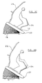
- Figure 3C illustrates the position of the skier over the deck 12 when the handrail 24 and the support rail 26 is pivoted together with the deck 12, in other words the angles of inclination of the handrail with respect to the ski surface remains constant.
- the applicant has recognised that, as can be seen in Figure 3C, the result is that the skier moves towards the front of the ski deck.
- a preferred implementation of the invention shown in Figure 3D thereby ensures that the angles of inclination of the handrail with respect to the base and with respect to the surface vary as the angle of inclination of the deck is varied. Furthermore, the angles of inclination of the support rail with respect to the base and with respect to the surface also vary as the angle of inclination of the deck is varied.
- the movement of the hand rail ensures a constant position of the user over the ski deck, and the movement of the support rail 26 is intended to provide a constant distance between the belt 30 and the cut-off switch 28 provided on the support rail 26, so that the cut-off switch remains operative.
- the constant user position enables the area of the deck to be reduced. Preferably, short skis are also used, to reduce the required area of the deck 12.
- Figure 4 shows in greater detail the system of linkages which provides the angular relationship between the handrail 24 and the support rail 26 shown in Figure 3D.
- the base 42 of the hand rail 24 is positionally fixed with respect to the base 18, and a pivot point 43 of the hand rail is positionally fixed with respect to the deck 20.
- the distance between these two points 42 and 43 is variable, as a hydraulic cylinder arrangement is provided.
- the base 50 of the support rail 26 is positionally fixed with respect to the base 18, and a support part 1 of the hand rail is positionally fixed with respect to the deck 20.
- the distance between these two points 50 and 41 is also variable, as a hydraulic cylinder arrangement 52 is provided.
- the distance between points 42 and 50 is fixed, as well as the distance between points 43 and 51.
- the pivoting of the deck takes place around a fixed pivot axis 54 which may or may not coincide with the axis of the front roller.
- the position of this axis 54 governs the way the angles of the hand rail and of the support rail vary as the deck angle is varied.
- Figure 4 One preferred system of angles is represented in Figure 4. As shown, the hand rail angle with respect to the deck 12 changes more slowly than the support rail angle with respect to the deck 12. For an incline of 30 degrees, the example illustrated in Figure 4 gives rise to an angular movement with respect to the deck of 13.7 degrees for the support rail and 12.4 degrees for the hand rail.
- the angle of the hand rail and of the support rail with respect to the base may change by between 1/3 and 2/3 of the change in the angle of inclination of the deck 20.
- the angle of the hand rail and of the support rail with respect to the deck then changes by between 2/3 and 1/3 of the change in the angle of inclination of the deck 20.
- a further possibility is to alter the height of the hand rail above the deck, as a function of the angle of inclination.
- “height” is meant the length of the upright arm of the hand rail from the deck.
- the distance between points 42 and 43 may again variable passively, as a function of the angle of inclination.
- the length of the hand rail above the point 43 may also be controllable by an independent drive mechanism.
- the hand rail may have an outer sleeve which is slidable over an inner core, and this slidine is then controlled by the drive mechanism.
- the slope increases, the hand rail rises, so that it remains in a position corresponding to the correct position in which the ski poles are to be held. This is shown in dotted lines in Figure 3D.
- Figure 5 shows the operation of the hydraulic cylinder arrangement 52 used to raise and lower the ski deck 20.
- the cylinder arrangement has a first cylindrical chamber 54 on one side of a piston 56 and a second annular chamber 58 on the opposite side of the piston 56.
- the area of a section through the first chamber 54 is approximately double the area of a section through the second chamber 58.
- the base of the piston rod 60 is fixed to the base 18 of the apparatus, and the sleeve 62 defines the contact point 51 where the support rail 26 is fixed to the upper frame 20.
- a pressure from a pressure source 64 is applied to both chambers by means of a valve arrangement 66. This results in a net force driving the support rail upwards.
- the pressure from the pressure source 64 is applied only to the second chamber 58, which results in a force driving the support rail downwards.
- the force up and down is equal, so that the deck can be controlled with a single, constant value, pressure source, to give equal raising and lowering speeds.
- the effect of gravity acting to increase the speed of decline of the deck is counteracted by the fluid resistance of an outlet valve from the first chamber. It is desirable to know the speed at which the deck 20 rises and falls so that the speed of the belt 14 can be controlled in appropriate manner when the incline of the deck is being changed.
- the support rail is driven by the hydraulic cylinder arrangement of Figure 5.
- Figure 6 shows schematically one possibility in which the rear part of the deck is caused to raise and lower using a scissor arrangement, in which an electric ball screw actuator 72 is used to control the extension or compression of the scissor arrangement, and thereby the height of the back of the deck.
- This provides a rapidly controllable movement.
- the pivot connections of the rails provide the desired angular movement of the rails as the deck is raised and lowered.
- Figure 7 shows a modification to the apparatus of Figure 1 incorporating a screen.
- the images are selected according to the setting of the angle of inclination of the deck, to improve the simulation.
- the screen may be used to show images and runs of a resort where a skier will be going while he or she is exercising in preparation for the holiday. The skier can thus get a feeling for the resort in advance.
- the screen may be used to sell advertising space to ski resort organisations or ski equipment suppliers.
- the screen may also include a camera so that the user can see images of himself or herself, and/or a mirror.
- the front of the deck may also be provided with a fan 80 or a series of fans 80, and the number of fans actuated, or else the speed of the fan or fans, is controlled as a function of the angle of inclination, to represent the skier's speed through the air.
- the ski deck is preferably mounted over the front and rear roller without being constrained laterally.
- the forces on the deck may result in lateral movement of the belt.
- Figure 7 shows a tracking control system to ensure correct alignment of the belt.
- a first sensor 82 is provided on each side of the belt. If the belt moves laterally enough to cover the sensor, reflection from the underside of the belt can be detected, and the axis 84 of the front roller can be shifted appropriately for a fixed time period, to force the belt back to a central lateral position.
- a second series of sensors 86 will detect further misalignment, indicating incorrect operation of the automatic tracking control system, and act as a safety cut-out.
- the sensors 82,86 may be detect reflection (for example comprising a light source such as a phototransistor and a light detector such as a photodiode) or alternatively a light source may be mounted above or below the belt with a light detector mounted on the opposite side of the belt, so that a light path is interrupted by the belt when it shifts laterally to a sufficient degree.
- a light source such as a phototransistor and a light detector such as a photodiode
- a light source may be mounted above or below the belt with a light detector mounted on the opposite side of the belt, so that a light path is interrupted by the belt when it shifts laterally to a sufficient degree.
- the outer perimeter of the deck may also be provided with line-of-sight sensors, so that any object projecting off the deck (such as a wrongly positioned ski) can cause a safety cut-out.
- These sensors may be provided all around the deck, or at least at the back of the deck.
- a further aspect of the invention provides users with an identity card which can be read by the simulator, which then allows the user to operate the machine to speeds or angles of inclination which match the user's level of experience.
- This identity card comprises a smart card, and a user may then be required to undergo basic training before obtaining a smart card, or before the smart card enables the user to operate the simulator without supervision.
- Figure 7 shows schematically a smart card reader 90 as part of the control panel 31.
- a user may be required to have three safety training lessons before the smart card will allow them to use the simulator independently. This enables a gym having the simulator to ensure the safety of users of the simulator.
- the user's smart card has been updated to indicate that the three lessons have been completed, the user may be able to ski on low gradient (green) slopes independently. An additional lesson will then allow the user access to the next gradient of slope. There may be four further slope gradients (blue, red, black, double diamond black), and the user may therefore be required to complete a seven lesson training schedule before being allowed to use the simulator to its full capability.
- the user may choose to see a pre-recorded video taken by a skier skiing the selected run, or else footage or information concerning a chosen resort.
- the footage of the run being skied may include a skier to be followed.
- the skier being followed will then be skiing at a level corresponding to the level of the lesson, so that the user will be instructed to copy the skier in front. This keeps the user looking forward and in an upright stance.
- a user authorised to use the simulator independently may also choose to follow a skier.
- the smart card may also be used to enable a user to follow a training schedule, with the simulator providing a tailor-made training routine for the user, in preparation for a ski holiday, for example.
- the smart card also contains information concerning the weight of the user, so that the ratio of angle of inclination to belt speed can be determined. It can also contain information concerning the height of the user, so that the extension of the hand rail can be tailored to the user, so that the users hands will always be positioned in the correct position for holding the ski poles.
- the angle of inclination remains constant.
- gradient information may be recorded at regular intervals, for example every metre. This can be achieved by measuring accurately the altitude using a GPS system.
- the angle of inclination and the belt speed may vary to mirror the image on the screen at that time.
- a force feedback system associated with the hand rail has been described in detail.
- a sensor may be provided for detecting the position of the user's boots, which should remain at a substantially constant height up the slope. The front or back of the user's skis will naturally rise and fall up and down the slope during turns, whereas the user's feet will not.
- a light probe and sensor arrangement may be provided for this purpose.
- the position of the body of the user may be monitored, either by attachment of a sensor to the user, or again by monitoring with an optical system. All of these possibilities are intended to be within the scope of the invention.
Landscapes
- Health & Medical Sciences (AREA)
- General Health & Medical Sciences (AREA)
- Physical Education & Sports Medicine (AREA)
- Cardiology (AREA)
- Vascular Medicine (AREA)
- Escalators And Moving Walkways (AREA)
- Road Paving Structures (AREA)
- Management, Administration, Business Operations System, And Electronic Commerce (AREA)
- Carbon And Carbon Compounds (AREA)
- Luminescent Compositions (AREA)
Abstract
Description
- This invention relates to ski simulators in the form of inclined treadmills. Such simulators may be used either for teaching skiing technique, or they may be used as an exercise apparatus, either for general fitness, or more specifically for training the muscle groups used in the sport of skiing.
- US 5,162,029 discloses a ski simulator comprising an inclined deck having a moving belt of material with a low coefficient of friction. A hand rail is provided towards the front of the simulator which the skier holds to maintain a position on the ski deck. A support rail is also provided behind the skier which supports a belt for attachment to the skier.
- It is also known that the angle of inclination of the ski surface may be adjustable and that the speed of the treadmill may be adjusted accordingly. A known apparatus having adjustable speed and angle inclination requires a supervisor to be present during use of the apparatus in order to continuously vary the speed of the treadmill according to the way the user of the apparatus is skiing.
- In addition to the problem of supervision, a further problem with the system described above is that holding on to a handrail reduces the realism of the ski simulator. For the user to be able to let go of the hand rail, the treadmill speed must result in the skier maintaining a substantially fixed position over the treadmill. If the supervisor of the system described above attempts to achieve this, there will inevitably be some movement of the skier up and down the treadmill as the speed is varied. This requires the treadmill to have an increased length. It is, however, desirable to reduce the overall size of the apparatus to enable it to be incorporated into a gymnasium alongside other fitness equipment.
- According to a first aspect of the application, there is provided an apparatus for simulating a ski slope comprising a ski deck having a surface defined by a continuous belt of material formed in a closed loop around rollers at the front and back of the ski deck, the belt of material being driven so that the surface of the ski deck rides up the slope, the angle of inclination of the deck with respect to a base of the apparatus and the drive speed of the material being controllable, wherein the apparatus further comprises a handrail towards the front of the deck, and wherein the angles of inclination of the handrail with respect to the base and with respect to the surface vary as the angle of inclination of the deck is varied.
- This arrangement of the handrail can be configured such that the natural position of the skier on the ski deck when holding the handrail remains substantially fixed as the angle of inclination of the ski deck is varied. In this way, the area of the ski deck can be minimised because the user remains substantially static with respect to the ski deck.
- Preferably, a support rail is provided towards the back of the deck, and the angles of inclination of the support rail with respect to the base and with respect to the surface also vary as the angle of inclination of the deck is varied. The support rail is preferably provided with a cut-off switch coupled to the user of the apparatus, such that if the user falls the cut-off switch is actuated.
- The movement of the support rail is therefore designed to keep the user at a fixed distance from the support rail, so that the cut-off switch remains functional at all angles of inclination of the ski deck.
- Preferably, the angles of inclination of the handrail and of the support rail with respect to the base change by an amount less than the change in the angle of inclination of the deck. It has been found that the inclination of the handrail and the support rail should not remain fixed with respect to the base, but neither should they remain fixed with respect to the ski deck, when the angle of inclination of the ski deck changes. It has been found that, for optimum comfort and positioning of the skier, the handrail and support rail should tilt, but to a lesser extent than the angular movement of the ski deck.
- The angle of inclination of the handrail with respect to the base may need to change by a different amount to the angle of inclination of the support rail with respect to the base, as the ski deck moves.
- The support rail and the hand rail may each have an extendable base, and the base of the hand rail and of the support rail may then be positionally fixed with respect to the base, and a support part of the hand rail and of the support rail may then be positionally fixed with respect to the deck. The base and the deck thus constitute a linkage mechanism which governs the angular movement of the support rail and the hand rail as the angle of inclination of the deck is varied.
- The extendable base of the hand rail and of the support rail may comprise at least one hydraulic cylinder, with the hydraulic cylinder at the base of the support rail being actuated to vary the angle of inclination of the deck. Alternatively, an electric motor or other arrangement may provide the extension of the base of one of the support rail or the hand rail, which varies the inclination of the deck.
- The axis about which the deck is able to pivot is preferably selected such that the angle of inclination of the handrail with respect to the base changes by a different amount to the angle of inclination of the support rail with respect to the base when the angle of inclination of the ski deck is varied.
- The height of the hand rail above the deck may also be varied as a function of the angle of inclination, so that the hand rail is at a height corresponding to the correct position of the hands for holding ski poles.
- According to a second aspect of the present application, there is provided an apparatus for simulating a ski slope comprising a ski deck having a surface defined by a continuous belt of material formed in a closed loop around rollers at the front and back of the ski deck, the belt of material being driven so that the surface of the ski deck rides up the slope, the angle of inclination of the deck with respect to a base of the apparatus and the drive speed of the material being controllable, wherein the apparatus further comprises a feedback system for controlling the drive speed as a function of the performance of the user.
- The use of feedback enables the speed to be controlled so that the skier can remain at a substantially fixed position, which may avoid the need for a hand rail. The feedback system may comprise a position sensor for detecting movement of the user up or down the slope, wherein if movement is detected towards the front of the deck the drive speed is increased and if movement is detected towards the back of the slope the drive speed is reduced.
- Alternatively and preferably, the apparatus may further comprise a hand rail towards the front of the deck and wherein the feedback system comprises a sensor for detecting the force applied by the user to the handrail, wherein if a force is detected on the handrail towards the front of the deck the drive speed is increased and if a force is detected on the handrail towards the back of the slope the drive speed is reduced. The use of force feedback from the handrail provides a simple feedback system. Once an appropriate speed has been reached corresponding to the manner in which the user is skiing, the user may let go of the hand rail and maintain a constant skiing rhythm. If the skier then wishes to ski in a different manner, for example with sharper turns, he can then hold on to the handrail, and the sharper turns will cause him to pull back on the handrail. Consequently, the speed will increase and the skier can then maintain a rhythm with sharper turns at a higher speed, and can again let go of the hand rail. Thus, once the user has adopted a particular skiing rhythm the apparatus will self-calibrate to provide the optimum skiing sensation.
- The handrail may be pivoted at its base, and the force sensor then detects the pivoting force of the handrail, forwards or backwards.
- The drive speed is preferably varied by up to predetermined maximum amounts above and below a default drive speed associated with the angle of inclination. This default speed may be selected as a function of the weight of the user.
- According to a third aspect of the application, there is provided an apparatus for simulating a ski slope comprising a ski deck having a surface defined by a continuous belt of material formed in a closed loop around rollers at the front and back of the ski deck, the belt of material being driven so that the surface of the ski deck rides up the slope, the angle of inclination of the deck with respect to a base of the apparatus and the drive speed of the material being controllable, wherein the apparatus comprises a card reader for reading a card of a user, and wherein the card reader is arranged to access information on the card and to cause the maximum angle of inclination of the deck to be limited dependent on that information.
- This enables the operator of the simulator to ensure that users have undergone sufficient training to be competent to use the apparatus safely, because their card will be updated to reflect their level of competence, so that they are only provided access to ski runs appropriate for their ability. The card reader may also be for reading information concerning the weight of the user, the apparatus determining the belt speed for different angles of inclination from the weight information. The card may be a magnetic swipe card or a swipe card.
- According to a fourth aspect of the application, there is provided an apparatus for simulating a ski slope comprising a ski deck having a surface defined by a continuous belt of material formed in a closed loop around rollers at the front and back of the ski deck, the belt of material being driven so that the surface of the ski deck rides up the slope, the angle of inclination of the deck with respect to a base of the apparatus and the drive speed of the material being controllable, the apparatus having a plurality of settings corresponding to different simulated ski conditions, each setting defining an associated drive speed and angle of inclination.
- The provision of a number of settings enables a user of the apparatus to select a setting corresponding to their skiing ability or the effort to be exerted during fitness training, and to use the apparatus without supervision. Preferably, the relationship between the drive speed and the angle of inclination for each setting can be varied as a function of the weight of the user. In this way, the default setting will be approximately sufficient for the drive speed to support the user without the user needing to apply a large force to the handrail.
- According to a fifth aspect of the invention, there is provided an apparatus for simulating a ski slope comprising a ski deck having a surface defined by a continuous belt of material formed in a closed loop around rollers at the front and back of the ski deck, the belt of material being driven so that the surface of the ski deck rides up the slope, the angle of inclination of the deck with respect to a base of the apparatus and the drive speed of the material being controllable, wherein the angle of inclination of the deck is controlled by at least one hydraulic cylinder having a first cylindrical chamber on one side of a piston and a second annular chamber on the opposite side of the piston, wherein the area of a section through the first chamber is approximately double the area of a section through the second chamber, and wherein a pressure is applied to both chambers to move the piston in one direction, whereas a pressure is applied only to the second chamber to move the piston in an opposite direction.
- This hydraulic cylinder arrangement enables the rising and falling of the ski deck to occur at the same speed, even with a single constant pressure source for the hydraulic cylinder. Accurate control of the speed at which the ski deck rises and falls enables the speed of the belt to be varied appropriately during the raising and towering of the ski deck. Thus, the drive speed is preferably controlled automatically to vary in a predetermined manner as the angle of inclination is varied.
- According to a sixth aspect of the invention, there is provided an apparatus for simulating a ski slope comprising a ski deck having a surface defined by a continuous belt of material formed in a closed loop around rollers at the front and back of the ski deck, the belt of material being driven so that the surface of the ski deck rides up the slope, the angle of inclination of the deck with respect to a base of the apparatus and the drive speed of the material being controllable, wherein the belt comprises a backing layer, a rubber ply layer bonded to the backing layer, and a polypropylene matting bonded to the rubber ply layer, the matting having bundles of strands projecting through openings in a support layer of the matting, the strands having a length between 15 and 30mm and the spacing between adjacent bundles of strands being less than 5mm.
- According to a seventh aspect of the invention, there is provided an apparatus for simulating a ski slope comprising a ski deck having a surface defined by a continuous belt of material formed in a closed loop around rollers at the front and back of the ski deck, the belt of material being driven so that the surface of the ski deck rides up the slope, the angle of inclination of the deck with respect to a base of the apparatus and the drive speed of the material being controllable, wherein the rotation axis of one of the rollers can be tilted, and wherein the apparatus further comprises a tracking control system comprising a sensor on each side of the belt for detecting lateral movement of the belt, and wherein if lateral movement of the belt is detected, the rotation axis is tilted for a predetermined time period.
- The features of each of the seven aspects of the invention may be combined in any combination to produce an apparatus for simulating a ski slope benefiting from advantages provided by this invention.
- The apparatus may be provided with a screen at the front of the deck for displaying images selected according to the setting of the angle of inclination of the deck. Aspects of this invention may enable the deck to have an area of less than 5 square meters. For example, the deck may have dimensions of approximately 2 meters x 2 meters, or even 1.5 meters x 1.5 meters. These dimensions make it practical for the apparatus to be placed alongside conventional gymnasium equipment.
- Examples of the present invention will now be described in detail with reference to the accompanying drawings, in which:
- Figure 1 shows an apparatus for simulating a ski slope according to the invention;
- Figure 2 shows a force sensor arrangement used in the apparatus of Figure 1;
- Figure 3 is a diagram illustrating how the position of the skier changes as the angle of inclination of the deck varies;
- Figure 4 shows in greater detail the arrangement used in the apparatus of Figure 1;
- Figure 5 shows a hydraulic piston arrangement used in the apparatus of Figure 1;
- Figure 6 shows an electric actuator used in the apparatus of Figure 1; and
- Figure 7 shows a modification to the apparatus of Figure 1 incorporating a screen.
- Figure 1 shows an
apparatus 10 for simulating a ski slope. Theapparatus 10 comprises aski deck 12 having a surface defined by a continuous belt ofmaterial 14 formed in a closed loop around rollers at the front and back of theski deck 12. Thebelt 14 is driven around the rollers, for example by an electric motor, so that the upper surface of thebelt 14 travels in the direction represented byarrow 16, which is up the slope when it is inclined. Theapparatus 10 has a fixedbase 18 and anupper frame 20. The front and back rollers are supported by theupper frame 20, and theupper frame 20 and thebelt 14 can pivot about an axis, which may coincide with the axis of rotation of the front roller. This enables the back of thedeck 12 to be raised, as represented byarrow 22. In this way, the angle of inclination of thedeck 12 with respect to thebase 18 is controllable. Furthermore, the drive speed of the belt ofmaterial 14 is also controllable, so that the drive speed is appropriate for the angle of inclination of thedeck 12. - The apparatus further comprises a
handrail 24 towards the front of thedeck 12 and asupport rail 26 towards the back of thedeck 12. A cut-off switch 28 is mounted on thesupport rail 26, and is coupled to abelt 30 to be worn by the user of the apparatus. Thebelt 30 and the cut-off switch 28 are arranged such that thedeck 12 is stopped if the user falls over. - During use of the apparatus, the user wears a pair of skis, or a snowboard, and stands in the middle of the
deck 12 holding thehandrail 24, and wearing thebelt 30. - When the
ski deck 12 is raised to an incline, the speed of the belt ofmaterial 14 is selected such that the forces on the skier up and down the slope are approximately equal, so that the user is in equilibrium. This equilibrium will depend not only on the speed of the belt and the angle of inclination of the belt, but also on the weight of the user, the surface of the skis used and the skiing style adopted by the user. To ensure the user remains on thedeck 12, thehandrail 24 is held during use of the apparatus. - To the extent described above, the apparatus is known. Improvements to the basic operation of the device described above are set out below.
- The apparatus is provided with a
control panel 31 which provides a number of settings corresponding to different ski runs. Each setting defines an associated drive speed and angle of inclination which can be reached automatically by the apparatus. The skier can thus select a setting corresponding to their skiing ability or the effort to be exerted during fitness training, and to use the apparatus without supervision. Preferably, the relationship between the drive speed and the angle of inclination for each setting can be varied as a function of the weight of the user, and thecontrol panel 31 thus has a weight input function for this purpose. In this way, the default setting will be approximately sufficient for the drive speed to support the user without the need to lean heavily or pull back heavily on the hand rail. - A preferred belt material has been found to be polypropylene matting, which has similar surface properties to fresh snow. A problem with the use of such material for artificial ski slopes has been that the performance degrades when the surface becomes dirty. The use of this material in the apparatus of the invention is particularly suitable because the rotation of the belt around the rollers provides a self-cleaning operation.
- In particular, a close pile polypropylene matting with short strand length has been found to best simulate the sensation of skiing on snow. In one example, the belt comprises a conventional frictional belt as a backing layer, a 3mm rubber ply layer bonded to the belt, and the close pile matting bonded to the rubber ply layer. The matting has strand lengths of between 15 and 25mm, preferably around 20mm. The spacing between adjacent bundles of strands projecting through individual holes in the backing of the matting is less than 6mm, and preferably around 5mm.
- In one example, the use of a feedback system for speed control is also provided. Figure 2 shows a
force sensor arrangement 40 associated with thehandrail 24 for detecting the force applied to thehandrail 24 by the user. Thehandrail 24 is pivoted at its base atpivot point 42 which enables the hand rail to tilt with respect to thebase 18. Furthermore, the hand rail is positionally fixed with respect to theupper frame 20 at apivot connection 43. Some slack is provided in this coupling to enable force detection, explained below. - A
spring arrangement 44 biases thehandrail 24 into a central default position with respect to theupper frame 20. When a force is applied to thehandrail 24 either forwards or backwards, thehandrail 24 is moved away from the central position, and this is detected by theforce feedback system 40. Detection of movement of thehandrail 24 may either be by a contact arrangement or by pressure sensors. The pivoting of thehandrail 24 either forward or backward is limited by theoval opening 47 which houses thepivot 43 and in the limit position a contact closes to indicate that a force greater than a preset minimum is being applied to thehandrail 24 either in a forward or a backward direction. The pivot connection between the upper and lower frames is not shown in Figure 2, but as described above this may coincide with the axis of the front roller. - The force feedback signal is used to control the drive speed of the belt of
material 14, so that when a force is detected on the handrail towards the front of the slope, the drive speed is increased, and when a force is detected on the handrail towards the back of the deck, the drive speed is reduced. In this way, the speed of the belt ofmaterial 14 is controlled automatically to match the skiing style, the weight, and the skis of the user to maintain the user in equilibrium. For example, if the user decides to practice sharper turns, this provides increased resistance which slows the user down. The effect of this is that the user will be dragged up the slope by the belt ofmaterial 14, and he will thereby pull back on thehandrail 24. The speed of the belt ofmaterial 14 will accordingly be reduced, and a new equilibrium will be found. - This may enable the skier to let go of the handrail once a rhythm in his skiing has been established.
- In an alternative arrangement, there is no force feedback system, and instead the user may be able to input manually a desired speed or speed change into the
control panel 31, whilst holding thehand rail 24 when getting used to the new speed setting. - Figure 3 illustrates the positioning of the skier on the
ski deck 12 at different angles of inclination of the deck. - As shown in Figure 3A for no incline, the position of the handle of the
handrail 24 is selected such that when a skier holding thehandrail 24 has the correct stance, the skis are positioned approximately in the middle of theski deck 12. When the angle of inclination is increased, as shown in Figure 3B, the skier's stance changes and in particular the skier's body remains substantially upright whereas the skier's knees are more flexed. - Figure 3B illustrates the position of the skier over the
deck 12 when thehandrail 24 and thesupport rail 26 remains at the same inclination with respect to the base. This could be achieved using a parallelogram coupling arrangement. The applicant has recognised that if the angle of inclination of the handrail with respect to the base remains constant then the skier moves towards the back of the ski deck, as shown, and becomes closer to thesupport rail 26. - Figure 3C illustrates the position of the skier over the
deck 12 when thehandrail 24 and thesupport rail 26 is pivoted together with thedeck 12, in other words the angles of inclination of the handrail with respect to the ski surface remains constant. The applicant has recognised that, as can be seen in Figure 3C, the result is that the skier moves towards the front of the ski deck. - Both of these situations require an enlarged skiing surface, since the position of the skier does not remain constant as the angle of inclination of the ski deck is changed. The position of the hand rail is also no longer comfortable in either situation.
- A preferred implementation of the invention shown in Figure 3D thereby ensures that the angles of inclination of the handrail with respect to the base and with respect to the surface vary as the angle of inclination of the deck is varied. Furthermore, the angles of inclination of the support rail with respect to the base and with respect to the surface also vary as the angle of inclination of the deck is varied.
- The movement of the hand rail ensures a constant position of the user over the ski deck, and the movement of the
support rail 26 is intended to provide a constant distance between thebelt 30 and the cut-off switch 28 provided on thesupport rail 26, so that the cut-off switch remains operative. The constant user position enables the area of the deck to be reduced. Preferably, short skis are also used, to reduce the required area of thedeck 12. - Figure 4 shows in greater detail the system of linkages which provides the angular relationship between the
handrail 24 and thesupport rail 26 shown in Figure 3D. As already shown in Figure 2, thebase 42 of thehand rail 24 is positionally fixed with respect to thebase 18, and apivot point 43 of the hand rail is positionally fixed with respect to thedeck 20. The distance between these twopoints support rail 26 is positionally fixed with respect to thebase 18, and a support part 1 of the hand rail is positionally fixed with respect to thedeck 20. The distance between these two points 50 and 41 is also variable, as ahydraulic cylinder arrangement 52 is provided. - Thus, the distance between
points 42 and 50 is fixed, as well as the distance betweenpoints pivot axis 54 which may or may not coincide with the axis of the front roller. The position of thisaxis 54 governs the way the angles of the hand rail and of the support rail vary as the deck angle is varied. - One preferred system of angles is represented in Figure 4. As shown, the hand rail angle with respect to the
deck 12 changes more slowly than the support rail angle with respect to thedeck 12. For an incline of 30 degrees, the example illustrated in Figure 4 gives rise to an angular movement with respect to the deck of 13.7 degrees for the support rail and 12.4 degrees for the hand rail. - Typically, the angle of the hand rail and of the support rail with respect to the base may change by between 1/3 and 2/3 of the change in the angle of inclination of the
deck 20. Correspondingly, the angle of the hand rail and of the support rail with respect to the deck then changes by between 2/3 and 1/3 of the change in the angle of inclination of thedeck 20. - A further possibility is to alter the height of the hand rail above the deck, as a function of the angle of inclination. By "height" is meant the length of the upright arm of the hand rail from the deck. The distance between
points point 43 may also be controllable by an independent drive mechanism. The hand rail may have an outer sleeve which is slidable over an inner core, and this slidine is then controlled by the drive mechanism. In particular, as the slope increases, the hand rail rises, so that it remains in a position corresponding to the correct position in which the ski poles are to be held. This is shown in dotted lines in Figure 3D. - Figure 5 shows the operation of the
hydraulic cylinder arrangement 52 used to raise and lower theski deck 20. The cylinder arrangement has a firstcylindrical chamber 54 on one side of apiston 56 and a secondannular chamber 58 on the opposite side of thepiston 56. The area of a section through thefirst chamber 54 is approximately double the area of a section through thesecond chamber 58. - The base of the
piston rod 60 is fixed to thebase 18 of the apparatus, and thesleeve 62 defines thecontact point 51 where thesupport rail 26 is fixed to theupper frame 20. In order to raise theski deck 20, a pressure from apressure source 64 is applied to both chambers by means of avalve arrangement 66. This results in a net force driving the support rail upwards. In order to lower theski deck 20, the pressure from thepressure source 64 is applied only to thesecond chamber 58, which results in a force driving the support rail downwards. - By virtue of the area relationship described above, the force up and down is equal, so that the deck can be controlled with a single, constant value, pressure source, to give equal raising and lowering speeds. During lowering of the ski deck, the effect of gravity acting to increase the speed of decline of the deck is counteracted by the fluid resistance of an outlet valve from the first chamber. It is desirable to know the speed at which the
deck 20 rises and falls so that the speed of thebelt 14 can be controlled in appropriate manner when the incline of the deck is being changed. - Only one of the hydraulic cylinders needs to be driven, since the support rail and hand rail are coupled by the linkage arrangement. Preferably, the support rail is driven by the hydraulic cylinder arrangement of Figure 5.
- It is also possible to use an electrical drive scheme for raising and lowering the ski deck, again with the angles of the rails being governed by the angle of inclination of the deck. All that is required is a drive arrangement for raising and lowering the deck, and the cylinder arrangement by which the bases of the hand rail and support rail are extendable may then be entirely passive.
- Figure 6 shows schematically one possibility in which the rear part of the deck is caused to raise and lower using a scissor arrangement, in which an electric
ball screw actuator 72 is used to control the extension or compression of the scissor arrangement, and thereby the height of the back of the deck. This provides a rapidly controllable movement. The pivot connections of the rails provide the desired angular movement of the rails as the deck is raised and lowered. - Figure 7 shows a modification to the apparatus of Figure 1 incorporating a screen. The images are selected according to the setting of the angle of inclination of the deck, to improve the simulation. The screen may be used to show images and runs of a resort where a skier will be going while he or she is exercising in preparation for the holiday. The skier can thus get a feeling for the resort in advance. When the apparatus is used in a gymnasium, the screen may be used to sell advertising space to ski resort organisations or ski equipment suppliers.
- The screen may also include a camera so that the user can see images of himself or herself, and/or a mirror.
- The front of the deck may also be provided with a
fan 80 or a series offans 80, and the number of fans actuated, or else the speed of the fan or fans, is controlled as a function of the angle of inclination, to represent the skier's speed through the air. - The ski deck is preferably mounted over the front and rear roller without being constrained laterally. The forces on the deck may result in lateral movement of the belt. Figure 7 shows a tracking control system to ensure correct alignment of the belt. A
first sensor 82 is provided on each side of the belt. If the belt moves laterally enough to cover the sensor, reflection from the underside of the belt can be detected, and theaxis 84 of the front roller can be shifted appropriately for a fixed time period, to force the belt back to a central lateral position. A second series ofsensors 86 will detect further misalignment, indicating incorrect operation of the automatic tracking control system, and act as a safety cut-out. Thesensors - The outer perimeter of the deck may also be provided with line-of-sight sensors, so that any object projecting off the deck (such as a wrongly positioned ski) can cause a safety cut-out. These sensors may be provided all around the deck, or at least at the back of the deck.
- It is described above that the user of the simulator will be able to ski in such a manner to reach an equilibrium with the belt speed. Of course, this may not be possible for a beginner, who will need to hold on to the hand rail. However, it may be considered desirable from a safety point of view for these beginners to be supervised. A further aspect of the invention provides users with an identity card which can be read by the simulator, which then allows the user to operate the machine to speeds or angles of inclination which match the user's level of experience. This identity card comprises a smart card, and a user may then be required to undergo basic training before obtaining a smart card, or before the smart card enables the user to operate the simulator without supervision.
- Figure 7 shows schematically a
smart card reader 90 as part of thecontrol panel 31. By way of example, a user may be required to have three safety training lessons before the smart card will allow them to use the simulator independently. This enables a gym having the simulator to ensure the safety of users of the simulator. Once the user's smart card has been updated to indicate that the three lessons have been completed, the user may be able to ski on low gradient (green) slopes independently. An additional lesson will then allow the user access to the next gradient of slope. There may be four further slope gradients (blue, red, black, double diamond black), and the user may therefore be required to complete a seven lesson training schedule before being allowed to use the simulator to its full capability. - The user may choose to see a pre-recorded video taken by a skier skiing the selected run, or else footage or information concerning a chosen resort. During a lesson, the footage of the run being skied may include a skier to be followed. The skier being followed will then be skiing at a level corresponding to the level of the lesson, so that the user will be instructed to copy the skier in front. This keeps the user looking forward and in an upright stance. A user authorised to use the simulator independently may also choose to follow a skier. The smart card may also be used to enable a user to follow a training schedule, with the simulator providing a tailor-made training routine for the user, in preparation for a ski holiday, for example.
- The smart card also contains information concerning the weight of the user, so that the ratio of angle of inclination to belt speed can be determined. It can also contain information concerning the height of the user, so that the extension of the hand rail can be tailored to the user, so that the users hands will always be positioned in the correct position for holding the ski poles.
- In the examples described above, it is assumed that for a given run, the angle of inclination remains constant. Instead, when recording footage of a run to be featured by the simulator, gradient information may be recorded at regular intervals, for example every metre. This can be achieved by measuring accurately the altitude using a GPS system. When the user skis the run, the angle of inclination and the belt speed may vary to mirror the image on the screen at that time.
- In respect of the feedback system for drive speed control, a force feedback system associated with the hand rail has been described in detail. However, other systems for detecting whether the user is tending to travel up or down the slope may be envisaged. For example a sensor may be provided for detecting the position of the user's boots, which should remain at a substantially constant height up the slope. The front or back of the user's skis will naturally rise and fall up and down the slope during turns, whereas the user's feet will not. A light probe and sensor arrangement may be provided for this purpose. Alternatively, the position of the body of the user may be monitored, either by attachment of a sensor to the user, or again by monitoring with an optical system. All of these possibilities are intended to be within the scope of the invention.
Claims (11)
- An apparatus (10) for simulating a ski slope comprising a ski deck (12) having a surface defined by a continuous belt of material (14) formed in a closed loop around rollers at the front and back of the ski deck, the belt of material being driven so that the surface of the ski deck rides up the slope, the angle of inclination of the deck with respect to a base (18) of the apparatus and the drive speed of the material being controllable, characterised in that the belt comprises a backing layer, a rubber ply layer bonded to the backing layer, and a polypropylene matting bonded to the rubber ply layer, the matting having bundles of strands projecting through openings in a support layer of the matting, the strands having a length between 15 and 25mm and the spacing between adjacent bundles of strands being less than 6mm.
- An apparatus as claimed in claim 1, further comprising a handrail (24) towards the front of the deck and wherein the angles of inclination of the handrail with respect to the base and with respect to the surface vary as the angle of inclination of the deck is varied.
- An apparatus as claimed in claim 2, further comprising a support rail (26) towards the back of the deck, and wherein the angles of inclination of the support rail with respect to the base and with respect to the surface also vary as the angle of inclination of the deck is varied.
- An apparatus as claimed in claim 3, wherein the angles of inclination of the handrail and of the support rail with respect to the base change by an amount less than the change in the angle of inclination of the deck.
- An apparatus as claimed in claim 4, wherein the angle of inclination of the hand rail with respect to the base changes by a different amount to the angle of inclination of the support rail with respect to the base.
- An apparatus as claimed in any one of claims 3 to 5, wherein the support rail and the hand rail have an extendable base, and wherein the base of the hand rail and of the support rail is positionally fixed with respect to the base, and a support part of the hand rail and of the support rail is positionally fixed with respect to the deck.
- An apparatus as claimed in claim 6, wherein the extendable base of the hand rail and of the support rail comprises at least one hydraulic cylinder (52), and wherein the hydraulic cylinder at the base of the support rail is actuated to vary the angle of inclination of the deck.
- An apparatus as claimed in claim 6, wherein the axis about which the deck is able to pivot is selected such that the angle of inclination of the handrail with respect to the base changes by a different amount to the angle of inclination of the support rail with respect to the base when the angle of inclination of the ski deck is varied.
- An apparatus as claimed in any one of claims 3 to 8, wherein the support rail is provided with a cut-off switch coupled to the user of the apparatus, such that if the user falls, the cut-off switch is actuated.
- An apparatus as claimed in any one of claims 2 to 9, wherein the height of the hand rail above the deck is varied as a function of the angle of inclination.
- An apparatus as claimed in any preceding claim, wherein the deck has an area of less than 5m2.
Applications Claiming Priority (5)
| Application Number | Priority Date | Filing Date | Title |
|---|---|---|---|
| GB9925132 | 1999-10-22 | ||
| GBGB9925132.4A GB9925132D0 (en) | 1999-10-22 | 1999-10-22 | Apparatus for simulating a ski slope |
| GB0021454A GB0021454D0 (en) | 1999-10-22 | 2000-08-31 | Apparatus for simulating a ski slope |
| GB0021454 | 2000-08-31 | ||
| PCT/GB2000/004063 WO2001030464A1 (en) | 1999-10-22 | 2000-10-20 | Apparatus for simulating a ski slope |
Publications (2)
| Publication Number | Publication Date |
|---|---|
| EP1225959A1 EP1225959A1 (en) | 2002-07-31 |
| EP1225959B1 true EP1225959B1 (en) | 2006-07-05 |
Family
ID=26244940
Family Applications (1)
| Application Number | Title | Priority Date | Filing Date |
|---|---|---|---|
| EP00971542A Expired - Lifetime EP1225959B1 (en) | 1999-10-22 | 2000-10-20 | Apparatus for simulating a ski slope |
Country Status (6)
| Country | Link |
|---|---|
| EP (1) | EP1225959B1 (en) |
| AT (1) | ATE332176T1 (en) |
| AU (1) | AU1038201A (en) |
| CA (1) | CA2426269A1 (en) |
| DE (1) | DE60029236D1 (en) |
| WO (1) | WO2001030464A1 (en) |
Cited By (2)
| Publication number | Priority date | Publication date | Assignee | Title |
|---|---|---|---|---|
| EP2379178A1 (en) * | 2008-10-14 | 2011-10-26 | Icon IP, Inc. | Exercise device with proximity sensor |
| WO2018065192A1 (en) * | 2016-10-05 | 2018-04-12 | Zebris Medical Gmbh | Treadmill with force sensor system integrated in the handrail |
Families Citing this family (10)
| Publication number | Priority date | Publication date | Assignee | Title |
|---|---|---|---|---|
| US7462139B2 (en) | 2001-06-12 | 2008-12-09 | Ireneusz Rabczak | Ski exercising and rehabilitation apparatus |
| GB2386566A (en) * | 2002-03-20 | 2003-09-24 | Triple Edge Ltd | Exercise and training apparatus |
| GB0804402D0 (en) * | 2008-03-10 | 2008-04-16 | Triple Edge Ltd | Interactive exercise device |
| NL2004512C2 (en) * | 2010-04-06 | 2011-10-10 | Tacx B V | Bicycle trainer. |
| NL2012657B1 (en) * | 2014-04-18 | 2016-07-04 | Tacx Roerend En Onroerend Goed B V | Exercise apparatus. |
| EP3233219B1 (en) | 2014-12-19 | 2023-10-04 | True Fitness Technology, Inc. | High-incline treadmill |
| US10857421B2 (en) | 2017-05-31 | 2020-12-08 | Nike, Inc. | Treadmill with dynamic belt tensioning mechanism |
| US10918904B2 (en) * | 2017-05-31 | 2021-02-16 | Nike, Inc. | Treadmill with vertically displaceable platform |
| SI25234A (en) * | 2017-10-04 | 2018-01-31 | Damjan Klampfer S.P. | Ski training device |
| CN109107131B (en) * | 2018-05-25 | 2023-09-01 | 深圳市和拓创新科技有限公司 | Intelligent bottom plate of intelligent skiing machine, data display system and offset processing method |
Family Cites Families (2)
| Publication number | Priority date | Publication date | Assignee | Title |
|---|---|---|---|---|
| US4344616A (en) * | 1980-08-05 | 1982-08-17 | Ralph Ogden | Exercise treadmill |
| US5162029A (en) | 1992-01-31 | 1992-11-10 | G. David Schine | Apparatus for teaching downhill skiing on a simulated ski slope |
-
2000
- 2000-10-20 WO PCT/GB2000/004063 patent/WO2001030464A1/en active IP Right Grant
- 2000-10-20 AU AU10382/01A patent/AU1038201A/en not_active Abandoned
- 2000-10-20 EP EP00971542A patent/EP1225959B1/en not_active Expired - Lifetime
- 2000-10-20 AT AT00971542T patent/ATE332176T1/en not_active IP Right Cessation
- 2000-10-20 CA CA002426269A patent/CA2426269A1/en not_active Abandoned
- 2000-10-20 DE DE60029236T patent/DE60029236D1/en not_active Expired - Lifetime
Cited By (3)
| Publication number | Priority date | Publication date | Assignee | Title |
|---|---|---|---|---|
| EP2379178A1 (en) * | 2008-10-14 | 2011-10-26 | Icon IP, Inc. | Exercise device with proximity sensor |
| EP2379178A4 (en) * | 2008-10-14 | 2015-06-17 | Icon Ip Inc | Exercise device with proximity sensor |
| WO2018065192A1 (en) * | 2016-10-05 | 2018-04-12 | Zebris Medical Gmbh | Treadmill with force sensor system integrated in the handrail |
Also Published As
| Publication number | Publication date |
|---|---|
| DE60029236D1 (en) | 2006-08-17 |
| EP1225959A1 (en) | 2002-07-31 |
| ATE332176T1 (en) | 2006-07-15 |
| CA2426269A1 (en) | 2001-05-03 |
| AU1038201A (en) | 2001-05-08 |
| WO2001030464A1 (en) | 2001-05-03 |
Similar Documents
| Publication | Publication Date | Title |
|---|---|---|
| EP1225959B1 (en) | Apparatus for simulating a ski slope | |
| US7344481B2 (en) | Treadmill with moveable console | |
| US10272317B2 (en) | Lighted pace feature in a treadmill | |
| US5580249A (en) | Apparatus for simulating mobility of a human | |
| US7303510B2 (en) | Bicycle training apparatus | |
| US5902214A (en) | Walk simulation apparatus | |
| US5205800A (en) | All terrain treadmill | |
| KR100762286B1 (en) | Treadmill system | |
| KR101317012B1 (en) | Ski simulation apparatus and simulation method of the same | |
| US5462503A (en) | Interactive exercise apparatus | |
| CA2967615A1 (en) | An integrated multi-purpose hockey skatemill and its control/management in the individual training and testing of the skating and hockey skills | |
| US5613856A (en) | Ski training system | |
| KR101780743B1 (en) | System For Supporting Cycling in Virtual Simulation Environment | |
| WO2019069276A1 (en) | Ski training machine | |
| KR101648059B1 (en) | Apparatus for ski simulation | |
| KR101579576B1 (en) | Ski jump simulator | |
| JP4949410B2 (en) | Exercise treadmill for towing and tensioning | |
| KR101935047B1 (en) | Exercise simulator | |
| CA3123585A1 (en) | An integrated multi-purpose hockey skatemill and its control/management in the individual training and testing of the skating and hockey skills | |
| EP2252378A2 (en) | Interactive exercising system | |
| KR101662635B1 (en) | a skateboard with sensors and skateboard simulation system using thereof | |
| KR101915639B1 (en) | A cycle apparatus using virtual reality | |
| JP3967612B2 (en) | Simulated skiing device using snow skiing tool and simulated skiing practice method | |
| KR102678402B1 (en) | Structure of ski plate | |
| KR101595299B1 (en) | ski simulation apparatus implementing rotation motion |
Legal Events
| Date | Code | Title | Description |
|---|---|---|---|
| PUAI | Public reference made under article 153(3) epc to a published international application that has entered the european phase |
Free format text: ORIGINAL CODE: 0009012 |
|
| 17P | Request for examination filed |
Effective date: 20020520 |
|
| AK | Designated contracting states |
Kind code of ref document: A1 Designated state(s): AT BE CH CY DE DK ES FI FR GB GR IE IT LI LU MC NL PT SE |
|
| AX | Request for extension of the european patent |
Free format text: AL;LT;LV;MK;RO;SI |
|
| GRAP | Despatch of communication of intention to grant a patent |
Free format text: ORIGINAL CODE: EPIDOSNIGR1 |
|
| GRAS | Grant fee paid |
Free format text: ORIGINAL CODE: EPIDOSNIGR3 |
|
| GRAA | (expected) grant |
Free format text: ORIGINAL CODE: 0009210 |
|
| AK | Designated contracting states |
Kind code of ref document: B1 Designated state(s): AT BE CH CY DE DK ES FI FR GB GR IE IT LI LU MC NL PT SE |
|
| PG25 | Lapsed in a contracting state [announced via postgrant information from national office to epo] |
Ref country code: IT Free format text: LAPSE BECAUSE OF FAILURE TO SUBMIT A TRANSLATION OF THE DESCRIPTION OR TO PAY THE FEE WITHIN THE PRESCRIBED TIME-LIMIT;WARNING: LAPSES OF ITALIAN PATENTS WITH EFFECTIVE DATE BEFORE 2007 MAY HAVE OCCURRED AT ANY TIME BEFORE 2007. THE CORRECT EFFECTIVE DATE MAY BE DIFFERENT FROM THE ONE RECORDED. Effective date: 20060705 Ref country code: AT Free format text: LAPSE BECAUSE OF FAILURE TO SUBMIT A TRANSLATION OF THE DESCRIPTION OR TO PAY THE FEE WITHIN THE PRESCRIBED TIME-LIMIT Effective date: 20060705 Ref country code: CH Free format text: LAPSE BECAUSE OF FAILURE TO SUBMIT A TRANSLATION OF THE DESCRIPTION OR TO PAY THE FEE WITHIN THE PRESCRIBED TIME-LIMIT Effective date: 20060705 Ref country code: NL Free format text: LAPSE BECAUSE OF FAILURE TO SUBMIT A TRANSLATION OF THE DESCRIPTION OR TO PAY THE FEE WITHIN THE PRESCRIBED TIME-LIMIT Effective date: 20060705 Ref country code: FI Free format text: LAPSE BECAUSE OF FAILURE TO SUBMIT A TRANSLATION OF THE DESCRIPTION OR TO PAY THE FEE WITHIN THE PRESCRIBED TIME-LIMIT Effective date: 20060705 Ref country code: BE Free format text: LAPSE BECAUSE OF FAILURE TO SUBMIT A TRANSLATION OF THE DESCRIPTION OR TO PAY THE FEE WITHIN THE PRESCRIBED TIME-LIMIT Effective date: 20060705 Ref country code: LI Free format text: LAPSE BECAUSE OF FAILURE TO SUBMIT A TRANSLATION OF THE DESCRIPTION OR TO PAY THE FEE WITHIN THE PRESCRIBED TIME-LIMIT Effective date: 20060705 |
|
| REG | Reference to a national code |
Ref country code: GB Ref legal event code: FG4D |
|
| REG | Reference to a national code |
Ref country code: CH Ref legal event code: EP |
|
| REG | Reference to a national code |
Ref country code: IE Ref legal event code: FG4D |
|
| REF | Corresponds to: |
Ref document number: 60029236 Country of ref document: DE Date of ref document: 20060817 Kind code of ref document: P |
|
| PG25 | Lapsed in a contracting state [announced via postgrant information from national office to epo] |
Ref country code: DK Free format text: LAPSE BECAUSE OF FAILURE TO SUBMIT A TRANSLATION OF THE DESCRIPTION OR TO PAY THE FEE WITHIN THE PRESCRIBED TIME-LIMIT Effective date: 20061005 Ref country code: SE Free format text: LAPSE BECAUSE OF FAILURE TO SUBMIT A TRANSLATION OF THE DESCRIPTION OR TO PAY THE FEE WITHIN THE PRESCRIBED TIME-LIMIT Effective date: 20061005 |
|
| PG25 | Lapsed in a contracting state [announced via postgrant information from national office to epo] |
Ref country code: DE Free format text: LAPSE BECAUSE OF FAILURE TO SUBMIT A TRANSLATION OF THE DESCRIPTION OR TO PAY THE FEE WITHIN THE PRESCRIBED TIME-LIMIT Effective date: 20061006 |
|
| PG25 | Lapsed in a contracting state [announced via postgrant information from national office to epo] |
Ref country code: ES Free format text: LAPSE BECAUSE OF FAILURE TO SUBMIT A TRANSLATION OF THE DESCRIPTION OR TO PAY THE FEE WITHIN THE PRESCRIBED TIME-LIMIT Effective date: 20061016 |
|
| PG25 | Lapsed in a contracting state [announced via postgrant information from national office to epo] |
Ref country code: IE Free format text: LAPSE BECAUSE OF NON-PAYMENT OF DUE FEES Effective date: 20061020 |
|
| PG25 | Lapsed in a contracting state [announced via postgrant information from national office to epo] |
Ref country code: MC Free format text: LAPSE BECAUSE OF NON-PAYMENT OF DUE FEES Effective date: 20061031 |
|
| NLV1 | Nl: lapsed or annulled due to failure to fulfill the requirements of art. 29p and 29m of the patents act | ||
| PG25 | Lapsed in a contracting state [announced via postgrant information from national office to epo] |
Ref country code: PT Free format text: LAPSE BECAUSE OF FAILURE TO SUBMIT A TRANSLATION OF THE DESCRIPTION OR TO PAY THE FEE WITHIN THE PRESCRIBED TIME-LIMIT Effective date: 20061205 |
|
| EN | Fr: translation not filed | ||
| PLBE | No opposition filed within time limit |
Free format text: ORIGINAL CODE: 0009261 |
|
| STAA | Information on the status of an ep patent application or granted ep patent |
Free format text: STATUS: NO OPPOSITION FILED WITHIN TIME LIMIT |
|
| 26N | No opposition filed |
Effective date: 20070410 |
|
| GBPC | Gb: european patent ceased through non-payment of renewal fee |
Effective date: 20061020 |
|
| PG25 | Lapsed in a contracting state [announced via postgrant information from national office to epo] |
Ref country code: GB Free format text: LAPSE BECAUSE OF NON-PAYMENT OF DUE FEES Effective date: 20061020 |
|
| PG25 | Lapsed in a contracting state [announced via postgrant information from national office to epo] |
Ref country code: GR Free format text: LAPSE BECAUSE OF FAILURE TO SUBMIT A TRANSLATION OF THE DESCRIPTION OR TO PAY THE FEE WITHIN THE PRESCRIBED TIME-LIMIT Effective date: 20061006 Ref country code: FR Free format text: LAPSE BECAUSE OF FAILURE TO SUBMIT A TRANSLATION OF THE DESCRIPTION OR TO PAY THE FEE WITHIN THE PRESCRIBED TIME-LIMIT Effective date: 20070511 |
|
| PG25 | Lapsed in a contracting state [announced via postgrant information from national office to epo] |
Ref country code: LU Free format text: LAPSE BECAUSE OF NON-PAYMENT OF DUE FEES Effective date: 20061020 |
|
| REG | Reference to a national code |
Ref country code: GB Ref legal event code: S28 |
|
| PG25 | Lapsed in a contracting state [announced via postgrant information from national office to epo] |
Ref country code: FR Free format text: LAPSE BECAUSE OF FAILURE TO SUBMIT A TRANSLATION OF THE DESCRIPTION OR TO PAY THE FEE WITHIN THE PRESCRIBED TIME-LIMIT Effective date: 20060705 Ref country code: CY Free format text: LAPSE BECAUSE OF FAILURE TO SUBMIT A TRANSLATION OF THE DESCRIPTION OR TO PAY THE FEE WITHIN THE PRESCRIBED TIME-LIMIT Effective date: 20060705 |
|
| REG | Reference to a national code |
Ref country code: GB Ref legal event code: S28 Free format text: APPLICATION WITHDRAWN Effective date: 20100809 |