EP1225820B1 - Device for dispensing a fluid product from a container - Google Patents
Device for dispensing a fluid product from a container Download PDFInfo
- Publication number
- EP1225820B1 EP1225820B1 EP00975920A EP00975920A EP1225820B1 EP 1225820 B1 EP1225820 B1 EP 1225820B1 EP 00975920 A EP00975920 A EP 00975920A EP 00975920 A EP00975920 A EP 00975920A EP 1225820 B1 EP1225820 B1 EP 1225820B1
- Authority
- EP
- European Patent Office
- Prior art keywords
- rotary body
- closure
- container
- rotating body
- body housing
- Prior art date
- Legal status (The legal status is an assumption and is not a legal conclusion. Google has not performed a legal analysis and makes no representation as to the accuracy of the status listed.)
- Expired - Lifetime
Links
Images


Classifications
-
- A—HUMAN NECESSITIES
- A45—HAND OR TRAVELLING ARTICLES
- A45D—HAIRDRESSING OR SHAVING EQUIPMENT; EQUIPMENT FOR COSMETICS OR COSMETIC TREATMENTS, e.g. FOR MANICURING OR PEDICURING
- A45D34/00—Containers or accessories specially adapted for handling liquid toiletry or cosmetic substances, e.g. perfumes
- A45D34/04—Appliances specially adapted for applying liquid, e.g. using roller or ball
- A45D34/041—Appliances specially adapted for applying liquid, e.g. using roller or ball using a roller, a disc or a ball
-
- A—HUMAN NECESSITIES
- A45—HAND OR TRAVELLING ARTICLES
- A45D—HAIRDRESSING OR SHAVING EQUIPMENT; EQUIPMENT FOR COSMETICS OR COSMETIC TREATMENTS, e.g. FOR MANICURING OR PEDICURING
- A45D40/00—Casings or accessories specially adapted for storing or handling solid or pasty toiletry or cosmetic substances, e.g. shaving soaps or lipsticks
- A45D40/22—Casings characterised by a hinged cover
Definitions
- the pivotable closure is brought into the closed position, which is clearly visible to the user, since in this position the rotary body is no longer visible, is ensured by the formation of the sealing means in cooperation with the closure inevitably and automatically, that the sealants are in their full operative position.
- the closure has on the inside at least one projection which presses against the sealing elements when pivoting into the closed position on the rotating body. In this way, the complete activation of the sealant when closing the closure can be realized particularly easily constructive.
- stops for limiting the pivoting movement of the closure are provided on the closure and / or on the rotary body housing and / or on the container. It is particularly advantageous provided that the attacks are assigned locking elements. For example, such locking elements may be provided to ensure that the closure remains in its open position when the device is in use. The same can also be provided for the closure position.
- the device according to the invention which is generally designated 6 (FIG. 14), initially has a roller applicator device, which includes a rotary body housing 7 and a rotary body 8 which is spherical in the exemplary embodiment and is rotatably trapped in the rotary body housing 7.
- the spherical rotary body 8 is accommodated in the rotary body housing 7 so that it protrudes in regions inwardly in the region of the container opening 5 and protrudes oppositely in regions outwardly from the rotary body housing 7. It is, as best seen in FIGS.
- a sealing element 21 is provided in the lower region of the rotary body housing 7, which projects into the container 1, a sealing element 21 is provided, which may be an integral part of the sealing body housing 7 or formed on this.
- the geometric design of the rotary body housing 7 with sealing element 21 relative to the rotary body 8 is such that when the shutter 9 is open no complete sealing of the rotary body 8 to the interior of the container 1, but on rotation of the rotary body 8 projecting into the container 1 surface of the rotating body 8 after wetting without significant loss of liquid can reach the outside accessible area to allow the application of the product.
Abstract
Description
Die Erfindung betrifft eine Vorrichtung zur Ausgabe eines fließfähigen Produktes aus einem Behälter mit einer eine Behälteröffnung nach außen verschließenden Rollerauftragseinrichtung, welche ein Drehkörpergehäuse für einen Drehkörper aufweist, in dem der Drehkörper drehbar gefangen ist und bei Gebrauch vom fließfähigen Produkt benetzbar ist, und mit einem den Drehkörper nach außen abdeckenden öffenbaren Verschluss, der gegenüber dem Drehkörper derart schwenkbar angelenkt ist, dass er in eine den Drehkörper freigebende Öffnungsposition und in eine den Drehkörper nach außen abdeckende Verschlussposition verschwenkbar ist, wobei zwischen dem Drehkörper und dem Drehkörpergehäuse Dichtelemente vorgesehen sind und wobei die Dichtelemente so ausgebildet sind, dass sie durch Verschwenken des Verschlusses in die Verschlussposition vollständig wirksam sind.The invention relates to a device for dispensing a flowable product from a container with a container opening outwardly closing roller applicator having a rotary body housing for a rotary body in which the rotary body is rotatably trapped and wetted in use of the flowable product, and with a Rotary body outwardly opening openable closure which is hinged relative to the rotary body such that it is pivotable in an opening position releasing the rotary body and in a closing position covering the rotating body outward, wherein between the rotating body and the rotary body housing sealing elements are provided and wherein the sealing elements are formed so that they are completely effective by pivoting the closure in the closed position.
Eine Vorrichtung, die insbesondere zur Abgabe eines flüssigen Deodorants geeignet ist, ist beispielsweise aus DE 195 21 508 A1 bekannt. Bei dieser bekannten Vorrichtung soll die Rollerauftragseinrichtung derart ausgestaltet sein, dass sie einerseits die Öffnung des Behälters sicher bei Nichtgebrauch verschließt und andererseits ein Nachfließen der Flüssigkeit bei Gebrauch sicherstellt. Dies soll bei der bekannten Vorrichtung dadurch erreicht werden, dass der Drehkörper um seine Drehachse fest drehbar gelagert ist, und dass die Behälteröffnung mittels eines Verschlussstückes eines Schiebeverschlusses zu verschließen ist. Zusätzlich ist auch noch eine auf den Behälter aufsetzbare Verschlusskappe vorgesehen. Da der Drehkörper der bekannten Vorrichtung sich nur mit einem Freiheitsgrad im Drehkörpergehäuse bewegen kann, nämlich nur eine Drehung um die Drehachse ausführen kann, kann der Drehkörper von einer mit der Behälteröffnung in Verbindung stehenden Schale des Drehkörpergehäuses untergriffen werden, so dass durch den Abstand zwischen Drehkörper und Schale bei Gebrauch das Nachfließen der Flüssigkeit und damit der Benetzungsgrad des Drehkörpers bestimmt werden kann. Die Handhabung einer solchen Vorrichtung ist jedoch noch nicht zufriedenstellend, da zum einen die Form der Applikation eingeschränkt ist, weil sich der Drehkörper nur um einen Freiheitsgrad drehen kann. Will der Anwender deshalb eine großflächigere Verteilung der Flüssigkeit, beispielsweise im Bereich seiner Achselhöhle erreichen, so muss er die Rollerauftragseinrichtung ggf. mehrmals parallel benachbart zueinander aufsetzen. Zum anderen ist von Nachteil, dass der Anwender vor und nach dem Gebrauch der Vorrichtung die Verschlusskappe abnehmen bzw. wieder aufsetzen muss, weil ohne Verschlusskappe keine ausreichende Dichtfunktion gegeben ist.A device that is particularly suitable for dispensing a liquid deodorant is known for example from DE 195 21 508 A1. In this known device, the roller applicator is to be designed such that on the one hand securely closes the opening of the container when not in use and on the other hand ensures a subsequent flow of the liquid in use. This is to be achieved in the known device in that the rotary body is mounted fixedly rotatable about its axis of rotation, and that the container opening is closed by means of a closure piece of a sliding closure. In addition, a cap which can be placed on the container is also provided. Since the rotary body of the known device can only move with one degree of freedom in the rotary body housing, namely can only perform a rotation about the axis of rotation, the rotary body can be attacked by a standing with the container opening shell of the rotary body housing, so that by the distance between the rotary body and shell in use, the Nachfließen the liquid and thus the degree of wetting of the rotating body can be determined. The However, handling such a device is still unsatisfactory because, on the one hand, the shape of the application is limited because the rotary body can rotate only by one degree of freedom. If the user therefore wants to achieve a distribution of the liquid over a larger area, for example in the region of his armpit, then he must place the roller applicator, if necessary, several times adjacent to each other in parallel. On the other hand, it is disadvantageous that the user must remove and / or replace the closure cap before and after the use of the device, because without a sealing cap there is no sufficient sealing function.
Beispielsweise aus DE 27 24 099 A1 ist eine Vorrichtung mit einer Rollerauftragseinrichtung mit einem kugelförmigen Drehkörper bekannt, der ein einfacheres Auftragen des Produktes auf die Haut ermöglicht. Jedoch benötigt auch diese Vorrichtung eine Verschlusskappe, welche im Verschlusszustand von innen gegen Dichtelemente des Drehkörpergehäuses drückt und dadurch den Behälter dicht verschließt, allerdings nur dann, wenn der Verschluss vollständig aufgeschraubt ist, was leicht zu Fehlbedienungen führen kann. Auch bei dieser Lösung muss deshalb vor dem Gebrauch die Verschlusskappe entfernt und nach dem Gebrauch wieder aufgesetzt werden, was die Handhabung entsprechend aufwendig macht. Außerdem weist diese Vorrichtung wie die anderen Vorrichtungen dieser Art häufig den Nachteil auf, dass die Benetzung des Drehkörpers mit flüssigem Produkt insbesondere bei der erstmaligen Ingebrauchnahme unbefriedigend erfolgt, was es für den Anwender häufig notwendig macht, den Drehkörper mehrmals mit einem Finger zu drehen. Dies ist offensichtlich umständlich und wenig komfortabel.For example, from DE 27 24 099 A1 discloses a device with a roller applicator device with a spherical rotary body is known, which allows a simpler application of the product to the skin. However, this device also requires a closure cap, which presses in the closure state from the inside against sealing elements of the rotary body housing and thereby tightly closes the container, but only if the closure is completely screwed on, which can easily lead to incorrect operation. Therefore, even with this solution, the cap must be removed before use and replaced after use, which makes the handling correspondingly expensive. In addition, this device, like the other devices of this type often has the disadvantage that the wetting of the rotating body with liquid product is unsatisfactory, especially at the first use, which often makes it necessary for the user to rotate the rotating body several times with one finger. This is obviously awkward and not very comfortable.
Aus FR-A-2 623 476 ist eine Vorrichtung mit einer Rollerauftragseinrichtung bekannt, die nicht direkt mit dem Behälterinhalt in Verbindung steht, sondem über einen Kanal, der von einem verschwenkbaren Verschluss öffen- bzw. schließbar ist. In geschlossener Position des Verschlusses, bei der der Drehkörper vom Verschluss nach außen abgedeckt ist, ist der Kanal so ausgerichtet, dass er keine Verbindung zwischen dem Drehkörper und dem Behälterinneren bereitstellt, in geöffneter Position des Verschlusses dagegen besteht eine Verbindung. Eine solche Vorrichtung ist jedoch nur zur Abgabe eines pastösen Produktes geeignet und bestimmt, für die Verwendung als Ausgabevorrichtung beispielsweise für flüssige Deodorants ist sie ungeeignet.From FR-A-2 623 476 there is known a device with a roller applicator which is not directly associated with the contents of the container, but via a channel which can be opened or closed by a pivotable shutter. In the closed position of the closure, wherein the rotating body is covered by the shutter to the outside, the channel is aligned so that it does not connect between the rotating body and the container interior provides, in the open position of the closure, however, there is a connection. However, such a device is suitable and intended only for dispensing a pasty product, for use as a dispenser, for example, for liquid deodorants, it is unsuitable.
Eine Vorrichtung der eingangs genannten Gattung ist aus der US-A-5842806 bekannt. Diese offenbart einen Klappdeckel zum Verschluss des Behälters, mit dem der Drehkörper abgedeckt werden kann und gleichzeitig eine um den Drehkörper umlaufende Dichtlippe radial gegen den Drehkörper verpresst wird, der durch diesen Pressdruck zudem tief in einen Sitz für den Drehkörper gedrückt wird. Hierdurch werden somit Dichteelemente wirksam.A device of the aforementioned type is known from US-A-5842806. This discloses a hinged lid for closing the container, with which the rotary body can be covered and at the same time a rotating around the rotary body sealing lip is pressed radially against the rotary body, which is also pressed by this pressing pressure deep into a seat for the rotary body. As a result, thus density elements are effective.
Der Erfindung liegt die Aufgabe zugrunde, eine gattungsgemäße Vorrichtung besonders ergonomisch auszubilden und damit die Handhabung zu erleichtern.The invention has for its object to form a generic device particularly ergonomic and thus to facilitate handling.
Diese Aufgabe wird erfindungsgemäß dadurch gelöst, dass der Drehkörper aus dem Drehkörpergehäuse bereichsweise nach innen in den Behälter hineinragt, dass der Verschluss schwenkbar am Drehkörpergehäuse angelenkt ist und dass der Verschluss nach Art eines teilkugelförmigen Klappvisiers ausgebildet ist.This object is achieved in that the rotary body from the rotary body housing partially projects inwardly into the container, that the closure is pivotally hinged to the rotary body housing and that the closure is designed in the manner of a part-spherical folding sight.
Der erfindungsgemäße Verschluss kann zum Öffnen und Verschließen so gehandhabt werden, wie dies bei Klappvisieren von beispielsweise Motorradhelmen üblich ist.The closure according to the invention can be handled for opening and closing, as is common in folding visors of, for example, motorcycle helmets.
Durch diese Ausführung von Behälter und Verschluss werden Bedienungsfehler nahezu vollständig vermieden. Wird nämlich der schwenkbare Verschluss in die Verschlussposition gebracht, welche für den Benutzer klar erkennbar ist, da in dieser Position der Drehkörper nicht mehr zu sehen ist, ist durch die Ausbildung der Dichtmittel im Zusammenwirken mit dem Verschluss zwangsläufig und automatisch gewährleistet, dass sich die Dichtmittel in ihrer vollständigen Wirkposition befinden. Dazu ist vorzugsweise vorgesehen, dass der Verschluss innenseitig wenigstens einen Vorsprung aufweist, der beim Verschwenken in die Verschlussposition auf den Drehkörper einwärts gegen die Dichtelemente drückt. Auf diese Weise läßt sich die vollständige Aktivierung der Dichtmittel beim Schließen des Verschlusses besonders leicht konstruktiv realisieren.This design of container and closure virtually eliminates operator error. Namely, the pivotable closure is brought into the closed position, which is clearly visible to the user, since in this position the rotary body is no longer visible, is ensured by the formation of the sealing means in cooperation with the closure inevitably and automatically, that the sealants are in their full operative position. For this purpose, it is preferably provided that the closure has on the inside at least one projection which presses against the sealing elements when pivoting into the closed position on the rotating body. In this way, the complete activation of the sealant when closing the closure can be realized particularly easily constructive.
Außerdem kann bei dieser Gestaltung des Verschlusses vorgesehen werden, diesen bei der Verschwenkbewegung von der Verschluss- in die Öffnungsposition und umgekehrt zwangsweise in Reibkontakt mit dem Drehkörper zu bringen, so dass der Drehkörper während des Verschwenkens des Verschlusses in Drehbewegung versetzt wird, wodurch automatisch eine Benetzung des Drehkörpers mit Produkt erfolgt, so dass die anschließende Produktapplikation wesentlich vereinfacht wird, denn ein umständliches Betätigen des Drehkörpers mit den Fingern oder dgl. ist nicht notwendig. Hierzu ist vorteilhaft, dass der Drehkörper aus dem Drehkörpergehäuse bereichsweise nach innen in den Behälter hineinragt.In addition, it can be provided in this design of the closure, this in the pivoting movement from the closure to the open position and vice versa forced to bring into frictional contact with the rotary body, so that the rotary body is set during pivoting of the closure in rotational movement, thereby automatically wetting the rotary body is done with product, so that the subsequent product application is considerably simplified, because a cumbersome operation of the rotary body with the fingers or the like. Is not necessary. For this purpose, it is advantageous that the rotary body protrudes from the rotary body housing partially inwardly into the container.
Bei dieser Gestaltung des Verschlusses ist ganz besonders bevorzugt vorgesehen, dass das Drehkörpergehäuse mit dem aus diesem bereichsweise herausragenden Drehkörper und der die Behälteröffnung aufweisende Bereich des Behälters gemeinsam eine kugelartige Form bilden. Der teilkugelförmige Verschluss liegt dann sowohl in Öffnungs- als auch Verschlussposition weitgehend vollständig am Behälter bzw. am Drehkörper an, so dass er nicht stört. Außerdem bietet die Vorrichtung bei dieser Gestaltung ein optisch besonders ansprechendes Erscheinungsbild.In this design of the closure is very particularly preferably provided that the rotary body housing together with the region of this outstanding rotary body and the container opening having portion of the container together form a spherical shape. The part-spherical closure is then largely completely in both the opening and closing position on the container or on the rotating body, so that it does not bother. In addition, the device in this design offers a visually appealing appearance.
Die Vorrichtung kann eine vormontierte Baugruppe bilden, wobei in Ausgestaltung vorgesehen sein kann, dass das Drehkörpergehäuse lösbar am Behälter befestigt ist. Eine lösbare Verbindung ermöglicht es, den Behälter bei Bedarf erneut mit Produkt zu befüllen. Außerdem können unterschiedliche Behältertypen mit ein- und derselben Vorrichtung ausgerüstet werden, so daß verschiedene Formgestaltungen verwendet werden können. Eine Serie bestehend aus mehreren unterschiedlichen Vorrichtungen ist günstiger herzustellen. Das Gehäuse kann aber auch aufgeschnappt bzw. -geprellt sein. Eine Wiederverwertung der Vorrichtung ist dann regelmäßig nicht vorgesehen.The device may form a preassembled module, wherein it may be provided in an embodiment that the rotary body housing is releasably secured to the container. A detachable connection makes it possible to refill the container with product if necessary. In addition, different types of containers can be equipped with one and the same device, so that different shapes can be used. A series consisting of several different devices is cheaper to manufacture. The housing can also be snapped or -geprellt. A recycling of the device is then not regularly provided.
Um die Handhabung weiter zu erleichtern, ist ferner vorgesehen, dass am Verschluss und/oder am Drehkörpergehäuse und/oder am Behälter Anschläge zur Begrenzung der Verschwenkbewegung des Verschlusses vorgesehen sind. Dabei ist ganz besonders vorteilhaft vorgesehen, dass den Anschlägen Rastelemente zugeordnet sind. So können solche Rastelemente beispielsweise vorgesehen sein, um sicherzustellen, dass beim Gebrauch der Vorrichtung der Verschluss in seiner Öffnungsposition verbleibt. Gleiches kann auch für die Verschlussposition vorgesehen sein.In order to further facilitate handling, it is further provided that stops for limiting the pivoting movement of the closure are provided on the closure and / or on the rotary body housing and / or on the container. It is particularly advantageous provided that the attacks are assigned locking elements. For example, such locking elements may be provided to ensure that the closure remains in its open position when the device is in use. The same can also be provided for the closure position.
Die Erfindung ist nachstehend anhand der Zeichnung beispielhaft näher erläutert. Diese zeigt in
- Fig. 1
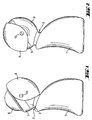
- eine Seitenansicht eines mit einer erfindungsgemäßen Vorrichtung ausgerüsteten Behälters in geöffneter Gebrauchsposition,
- Fig. 2
- den Behälter nach Fig. 1 in geschlossener Nichtgebrauchsposition,
- Fig. 3
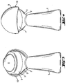
- den Behälter nach Fig. 1 in einer Ansicht von links,
- Fig. 4
- den Behälter nach Fig. 2 in einer Ansicht von links,
- Fig. 5
- eine Seitenansicht des Behälters ohne erfindungsgemäße Vorrichtung,
- Fig. 6
- ein vergrößertes Detail des Behälters nach Fig. 5 mit Behälteröffnung,
- Fig. 7
- eine Draufsicht auf die Behälteröffnung nach Fig. 6,
- Fig. 8
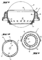
- einen Längsschitt durch das Drehkörpergehäuse (mit Drehkörper) der erfindungsgemäßen Vorrichtung,
- Fig. 9
- eine Ansicht von unten auf Fig. 8,
- Fig. 10
- eine Ansicht von unten auf den Verschluss der erfindungsgemäßen Vorrichtung,
- Fig. 11
- den Verschluss nach Fig. 10 in Seitenansicht, teilweise im Schnitt,
- Fig. 12
- eine Ansicht von links auf den Verschluss nach Fig. 11,
- Fig. 13
- im Längsschnitt den oberen Bereich des Behälters mit erfindungsgemäßer Vorrichtung in geschlossener Verschlussposition und in
- Fig. 14
- ebenfalls im Schnitt nur die erfindungsgemäße Vorrichtung.
- Fig. 1
- a side view of an equipped with a device according to the invention container in the open position of use,
- Fig. 2
- the container of Figure 1 in the closed non-use position,
- Fig. 3
- the container of FIG. 1 in a view from the left,
- Fig. 4
- the container of FIG. 2 in a view from the left,
- Fig. 5
- a side view of the container without device according to the invention,
- Fig. 6
- an enlarged detail of the container of FIG. 5 with container opening,
- Fig. 7
- a top view of the container opening of FIG. 6,
- Fig. 8
- a longitudinal section through the rotary body housing (with rotary body) of the device according to the invention,
- Fig. 9
- a bottom view of Fig. 8,
- Fig. 10
- a view from below of the closure of the device according to the invention,
- Fig. 11
- the closure of FIG. 10 in side view, partly in section,
- Fig. 12
- a view from the left on the closure of FIG. 11,
- Fig. 13
- in longitudinal section, the upper portion of the container with inventive device in closed closed position and in
- Fig. 14
- also in section only the device according to the invention.
Ein Behälter für ein fließfähiges Produkt, beispielsweise ein flüssiges Deodorant, ist in den Zeichnungen allgemein mit 1 bezeichnet. Dieser Behälter 1 weist beim dargestellten Ausführungsbeispiel zum Halten mit einer Hand eine besonders günstige, ergonomisch gestaltete äußere Kontur auf und ist in seinem oberen Bereich 2 halsförmig verjüngt ausgebildet. An diesen Bereich schließt sich ein etwa halbkugelförmiger Kopfbereich 3 an, welcher über einen leicht verjüngten, mit einem Außengewinde 4 ausgerüsteten Bereich in eine Behälteröffnung 5 mündet.
Dabei dient das Außengewinde des Kopfbereiches 3 des Behälters 1 zum Aufschrauben einer nachfolgend näher beschriebenen erfindungsgemäßen Vorrichtung zur Ausgabe des fließfähigen Produktes aus dem Behälter 1. Diese Vorrichtung kann, auch wenn dies in den Ausführungsbeispielen nicht dargestellt ist, auch Bestandteil des Behälters 1, d.h. nicht lösbar an diesem angeordnet sein. Ferner kann die Vorrichtung auch mittels einer Schnappverbindung am Behälter befestigt oder aufgeprellt sein.A container for a flowable product, for example a liquid deodorant, is indicated generally at 1 in the drawings. This
Here, the external thread of the
Die erfindungsgemäße Vorrichtung, die allgemein mit 6 bezeichnet ist (Fig. 14), weist zunächst eine Rollerauftragseinrichtung auf, welche ein Drehkörpergehäuse 7 sowie einen beim Ausführungsbeispiel kugelförmigen Drehkörper 8 beinhaltet, der drehbar im Drehkörpergehäuse 7 gefangen ist. Dabei ist, wie dies aus den Zeichnungen zu ersehen ist, der kugelförmige Drehkörper 8 so im Drehkörpergehäuse 7 aufgenommen, dass er bereichsweise nach innen in den Bereich der Behälteröffnung 5 hineinragt und gegenüberliegend bereichsweise nach außen aus dem Drehkörpergehäuse 7 herausragt. Dabei ist, wie am besten aus Fig. 1 bis 4 zu erkennen ist, vorzugsweise die Ausbildung der Außenkontur des Drehkörpergehäuses 7 in Verbindung mit dem herausragenden Bereich des Drehkörpers 8 so gestaltet, dass in am Behälter 1 montierter Lage der Vorrichtung 6 diese Bereiche gemeinsam mit dem halbkugelförmigen Kopfbereich 3 des Behälters 1 annähernd eine kugelartige Form bilden.The device according to the invention, which is generally designated 6 (FIG. 14), initially has a roller applicator device, which includes a
Die erfindungsgemäße Vorrichtung 6 weist darüber hinaus einen in Nichtgebrauchslage den Drehkörper 8 nach außen abdeckenden, offenbaren Verschluss 9 auf, welcher in erfindungswesentlicher Gestaltung gegenüber dem Drehkörper 8 derart schwenkbar angelenkt ist, dass er in eine den Drehkörper 8 freigebende Öffnungsposition und in eine den Drehkörper 8 nach außen abdeckende Verschlussposition verschwenkbar ist.The
Dazu ist der verschwenkbare Verschluss 9 bei den Ausführungsbeispielen schwenkbar am Drehkörpergehäuse 7 angelenkt, entsprechende Schwenkzapfen an gegenüberliegenden Außenseiten des Drehkörpergehäuses 7 sind mit 10 bezeichnet. Dementsprechend sind am Verschluss 9 von den Zapfen 10 durchdrungene Ausnehmungen 11 vorgesehen.For this purpose, the
In Anpassung an die Form des halbkugelförmigen Kopfbereiches 3 des Drehkörper gehäuses 7 und des kugelförmigen Drehkörpers 8 ist der Verschluss 9 vorzugsweise nach Art eines teilkugelförmigen Klappvisiers ausgebildet, wie dies in den Ausführungsbeispielen dargestellt ist.In adaptation to the shape of the
Wie ohne weiteres aus den Fig. 1 bis 4 erkennbar, lässt sich somit der Verschluss 9 von der Öffnungsposition (von außen frei zugänglicher Drehkörper 8 gemäß Fig. 1 und 3) in die Verschlussposition (Fig. 2 und 4) verschwenken, in welcher der Drehkörper 8 vom Verschluss 9 nach außen abgedeckt ist. In der Öffnungsposition gemäß Fig. 1 und 3 kann der Behälter 1 mit Vorrichtung 6 nach Art eines üblichen Deorollers benutzt werden. Um dabei zu verhindern, dass durch unsachgemäße Handhabung der Verschluss 9 in die Verschlussposition verschwenken kann, sind am Verschluss 9 und/oder am Drehkörpergehäuse 7 und/oder am Behälter 1 Anschläge vorgesehen. Diese Anschläge sind beispielsweise beim Verschluss 9 von innenseitig verdickten Randbereichen 12 gebildet, die gleichzeitig auch als Rastelemente dienen können. Ferner können am Kopfbereich 3 des Behälters 1 beidseitig angrenzend an die Schwenkzapfen 10 des Drehkörpergehäuses 7 bogenförmige, an den Schwenkweg angepasste Führungseinbuchtungen 13 vorgesehen sein, die in einen Endanschlag 14 münden und im Zusammenwirken mit an der Innenseite angrenzend an die Ausnehmungen 11 am Verschluss 9 vorgesehenen Vorsprüngen 15 stehen. Bei der Verschwenkung des Verschlusses 9 in die Öffnungsposition können die Vorsprünge 15 dann jeweils an der Führungseinbuchtung 13 entlanggleiten, bis sie in maximaler Öffnungsposition des Verschlusses 9 am Endanschlag 14 anschlagen. Alternativ können die Ausnehmungen bzw. Anschläge auch umgekehrt angeordnet sein, also statt am Verschluss am Behälter und umgekehrt.As can readily be seen from FIGS. 1 to 4, the
In der Verschlussposition wird das Anschlagen und Verrasten des Verschlusses 9 durch rastende Anlage der beidseitig gegenüberliegenden innenverdickten Anschläge 12 am Verschluss bewirkt, die am oberen umlaufenden ringförmigen Randbereich 17 des Drehkörpergehäuses 7 zur Anlage kommen.In the closed position, the striking and locking of the
Der Aufbau des Dichtkörpergehäuses 7 geht im einzelnen am besten aus den Fig. 8 und 9 hervor. Das Dichtkörpergehäuse 7 weist zunächst einen inneren, an die Geometrie des kugelförmigen Drehkörpers 8 angepassten teilkugelförmigen Aufnahmebereich 18 auf, an den sich außenseitig ein ringförmiges Anschlussstück 19 mit Innengewinde 20 anschließt, welches mit dem Außengewinde 4 des Behälters 1 zusammenwirkt. Durch geeignete Gestaltung der Gewinde 20 bzw. 4 und/oder geeignet vorgesehene Anschläge am Behälter 1 bzw. am Drehkörpergehäuse 7 ist dabei sichergestellt, dass sich nach dem vollständigen Aufschrauben des Drehkörpergehäuses 7 auf den Kopfbereich 3 des Behälters 1 das Drehkörpergehäuse 7 in der in den Fig. 1 bis 4 gezeigten Lage befindet, um ein einwandfreies Verschwenken des Verschlusses 9 zu ermöglichen. Anstelle der Schraubverbindung kann auch eine lösbare oder unlösbare Schnappverbindung vorgesehen sein.The construction of the sealing
Im unteren Bereich des Drehkörpergehäuses 7, welcher in den Behälter 1 hineinragt, ist ein Dichtelement 21 vorgesehen, welches integraler Bestandteil des Dichtkörpergehäuses 7 oder an dieses angeformt sein kann. Die geometrische Ausbildung des Drehkörpergehäuses 7 mit Dichtelement 21 gegenüber dem Drehkörper 8 ist dabei derart, dass bei geöffnetem Verschluss 9 keine vollständige Abdichtung des Drehkörpers 8 zum Inneren des Behälters 1 besteht, vielmehr bei Drehen des Drehkörpers 8 die in den Behälter 1 hineinragende Fläche des Drehkörpers 8 nach Benetzung ohne wesentlichen Verlust an Flüssigkeit in den außen zugänglichen Bereich gelangen kann, um die Auftragung des Produktes zu ermöglichen.In the lower region of the
Der obere Randbereich 23 des Drehkörpergehäuses 7 ist vorzugsweise als Lippenkontur ausgebildet, weiche es ermöglicht, dass in Überkopfstellung des Behälters 1 sich der kugelförmige Drehkörper so präzise an die Lippenkontur 23 anlegt, dass ein unerwünschtes Auslaufen des Produktes vermieden wird.The
Die Funktionsweise der erfindungsgemäßen Vorrichtung 6 ist die folgende: Ausgehend von der geschlossenen Position des Verschlusses 9 gemäß Fig. 2 und 4 kann der Benutzer den Behälter 1 mit einer Hand ergreifen und beispielsweise nur mit dem Daumen dieser Hand den Verschluss 9 in die in Fig. 1 gezeigte Öffnungsposition verschwenken, wobei der maximale Verschwenkwinkel durch die vorbeschriebenen Anschläge und Rastelemente begrenzt bzw. festgelegt ist. Der Behälter mit der Abgabevorrichtung 6 ist direkt einsatzbereit, es kann sofort ohne weitere Maßnahmen, beispielsweise ohne eine umständliche Fingerbetätigung des Drehkörpers 8 vom Drehkörper 8 Produkt an die Haut abgegeben werden.The operation of the
Nach dem Gebrauch wird der Verschluss 9 wieder in seine Verschlussposition zurückgeschwenkt, während dieses Verschließvorganges wird üblicherweise der Behälter 1 vom Benutzer aufrechtgehalten. Bei der Verschwenkbewegung des Verschlusses 9 wird automatisch aufgrund der Anschläge 12 und insbesondere aufgrund eines erhabenen vorsprungartigen Druckelementes 16 eine Druckkraft auf den Drehkörper 8 in axialer Richtung auf das Dichtelement 21 des Drehkörpergehäuses 7 hin ausgeübt, in geschlossener Lage verbleibt dabei das Druckelement 16 in Andrückposition. Dies führt dazu, dass der Drehkörper 8 dichtend gegen das Dichtelement 21 anliegt, so dass ein dichter Abschluss des Behälters 1 in Verschlussposition gewährleistet ist. Außerdem ist darüber hinaus der nach außen ragende Bereich des Drehkörpers 8 weitgehend durch den Verschluss 9 nach außen dicht abgeschlossen.After use, the
Eine Unterstützung der Öffnungs- bzw. Schließbewegung erfolgt durch ein an der Oberseite des Verschlusses 9 angeordnetes (nicht dargestelltes) Betätigungsmittel. Die Betätigungsmittel erstrecken sich quer zur Bewegungsrichtung des Verschlusses 9 und sind erhaben ausgebildet, so daß der Daumen während der Betätigung nicht abrutscht. Der Bereich, den das/die Betätigungsmittel einnimmt/einnehmen, entspricht in etwa der Fläche der Daumenkuppe. Zusätzlich können noch Indikationsmittel wie Pfeile angeordnet sein, welche den Anwender auf den Auflagebereich für den Daumen und/oder die Bewegungsrichtung hinweisen.Supporting the opening or closing movement takes place by means of an actuating means arranged on the upper side of the closure 9 (not shown). The actuating means extend transversely to the direction of movement of the
Natürlich ist die Erfindung nicht auf die dargestellten Ausführungsbeispiele beschränkt. Weitere Ausgestaltungen sind möglich, ohne den Grundgedanken zu verlassen. So ist es offensichtlich, dass je nach Ausführungsfall das Drehkörpergehäuse 7 aus ein oder mehreren Materialien hergestellt werden kann, um die unterschiedlichen Eigenschaften dieses Bauteils optimal ausbilden zu können.Of course, the invention is not limited to the illustrated embodiments. Further embodiments are possible without departing from the basic idea. Thus, it is obvious that, depending on the embodiment, the
So kann insbesondere der Bereich des Dichtelementes 21, das gleichzeitig auch als Abstreifer ausgebildet sein kann, durch geeignete Materialauswahl ausreichend flexibel und elastisch im Zusammenwirken mit dem Drehkörper 8 und dem Verschluss ausgewählt werden. Durch geeignete Auswahl und Dimensionierung dieser Elemente in Verbindung auch mit dem Freiraum des Drehkörpers 8 im Drehkörpergehäuse 7 läßt sich beeinflussen, wieviel Produkt der Drehkörper 8 auf dem Weg zur Applizieraußenseite mitnimmt.Thus, in particular, the region of the sealing
Bei einer nicht dargestellten Ausführungsform ist die Verschwenkbewegung des Verschlusses durch die Form des Drehkörpergehäuses begrenzt. In der Öffnungsposition liegt die in Öffnungsbewegungsrichtung vordere Kante des Verschlusses an der halsförmigen Verjüngung zwischen dem halbkugelförmigen Kopfbereich und dem Behälter an. In der Schließposition schlägt die hintere Kante an einen unterhalb der Behälteröffnung angeordneten Anschlag an, wobei dann die Kante des Verschlusses und der Anschlag formschlüssig aneinanderliegen.In one embodiment, not shown, the pivoting movement of the closure is limited by the shape of the rotary body housing. In the open position, the front edge of the closure in the direction of opening movement abuts the neck-shaped taper between the hemispherical head portion and the container. In the closed position, the rear edge abuts against a arranged below the container opening stop, in which case the edge of the closure and the stop abut positively.
Claims (4)
- Device for dispensing a flowable product from a container with a roller applicator device, which closes a container opening outwardly and which comprises a rotary body housing for a rotary body, in which the rotary body is rotatably caught and in the case of use is wettable by the flowable product, and with an openable closure which covers the rotary body outwardly and which is articulated to be pivotable relative to the rotary body (8) in such a manner that it is pivotable into an opening position freeing the rotary body (8) and a closing position covering the rotary body (8) towards the outside, wherein sealing elements are provided between the rotary body and the rotary body housing and wherein the sealing elements (21) are so constructed that they are completely effective by pivotation of the closure (9) into the closing position, characterised in that the rotary body protrudes from the rotary body housing regionally inwardly into the container, that the closure (9) is pivotably articulated to the rotary body housing (7) and that the closure (9) is constructed in the manner of a part-spherical folding visor.
- Device according to claim 1, characterised in that the closure (9) has at the inner side at least one projection (16) which on pivotation into the closing position presses inwardly onto the rotary body (8) towards the sealing elements (21).
- Device according to claim 1 or 2, characterised in that abutments for limitation of the pivot movement of the closure (9) are provided at the closure (9) and/or at the rotary body housing (7) and/or at the container (1).
- Device according to claim 3, characterised in that detent elements are associated with the abutments.
Applications Claiming Priority (3)
| Application Number | Priority Date | Filing Date | Title |
|---|---|---|---|
| DE19953258A DE19953258C2 (en) | 1999-11-04 | 1999-11-04 | Device for dispensing a flowable product from a container |
| DE19953258 | 1999-11-04 | ||
| PCT/EP2000/010536 WO2001032050A1 (en) | 1999-11-04 | 2000-10-26 | Device for dispensing a fluid product from a container |
Publications (2)
| Publication Number | Publication Date |
|---|---|
| EP1225820A1 EP1225820A1 (en) | 2002-07-31 |
| EP1225820B1 true EP1225820B1 (en) | 2006-04-05 |
Family
ID=7928010
Family Applications (1)
| Application Number | Title | Priority Date | Filing Date |
|---|---|---|---|
| EP00975920A Expired - Lifetime EP1225820B1 (en) | 1999-11-04 | 2000-10-26 | Device for dispensing a fluid product from a container |
Country Status (17)
| Country | Link |
|---|---|
| US (1) | US6814520B1 (en) |
| EP (1) | EP1225820B1 (en) |
| JP (1) | JP2003512978A (en) |
| AT (1) | ATE322192T1 (en) |
| AU (1) | AU774709B2 (en) |
| BR (1) | BR0015359A (en) |
| CA (1) | CA2390120A1 (en) |
| CZ (1) | CZ20021506A3 (en) |
| DE (2) | DE19953258C2 (en) |
| ES (1) | ES2260066T3 (en) |
| HR (1) | HRP20020343A2 (en) |
| HU (1) | HUP0203229A3 (en) |
| PL (1) | PL354573A1 (en) |
| RU (1) | RU2275829C2 (en) |
| SK (1) | SK7792002A3 (en) |
| TR (1) | TR200200983T2 (en) |
| WO (1) | WO2001032050A1 (en) |
Families Citing this family (11)
| Publication number | Priority date | Publication date | Assignee | Title |
|---|---|---|---|---|
| DE19953258C2 (en) * | 1999-11-04 | 2003-04-10 | Henkel Kgaa | Device for dispensing a flowable product from a container |
| GB2439061B (en) * | 2006-06-14 | 2011-06-15 | Adam Foster Robert Sutcliffe | A dispenser |
| GB0721186D0 (en) * | 2007-10-29 | 2007-12-05 | Carbonite Corp | Applications |
| US8356952B2 (en) * | 2008-01-15 | 2013-01-22 | Rexam Beauty And Closures, Inc. | Compact container for liquid cosmetic |
| WO2012011911A1 (en) | 2010-07-22 | 2012-01-26 | Colgate-Palmolive Company | Packaging for a consumer product |
| EP2654489A2 (en) * | 2010-12-21 | 2013-10-30 | Colgate-Palmolive Company | Consumer care packaging |
| ES2509268T3 (en) * | 2010-12-21 | 2014-10-17 | Colgate-Palmolive Company | Packaging for consumer products |
| US8844543B2 (en) * | 2011-08-24 | 2014-09-30 | Elc Management Llc | Concave-convex roller assembly |
| CH706012A1 (en) * | 2012-01-11 | 2013-07-15 | Alpla Werke | Plastic container for a roll-on deodorant. |
| FR3086146B1 (en) * | 2018-09-26 | 2022-01-28 | Chanel Parfums Beaute | BOTTLE COMPRISING A ROLL-ON APPLICATOR AND A STOPPER |
| RU199827U1 (en) * | 2020-02-04 | 2020-09-22 | Федеральное государственное бюджетное образовательное учреждение высшего образования "Астраханский государственный технический университет" (ФГБОУ ВО "АГТУ") | ROLLER FOOD FLAVOR CONTAINER |
Family Cites Families (11)
| Publication number | Priority date | Publication date | Assignee | Title |
|---|---|---|---|---|
| US2081673A (en) | 1936-03-07 | 1937-05-25 | Gordon L Olson | Applicator for plastic material and the like |
| US2912708A (en) | 1958-03-24 | 1959-11-17 | Owens Illinois Glass Co | Applicating device |
| US3103691A (en) | 1960-11-02 | 1963-09-17 | Morton B Stull | Roll-on dispensing cap |
| US3055041A (en) | 1961-01-04 | 1962-09-25 | Owens Illinois Glass Co | Ball applicator assembly with shuttletype closure |
| CA1078783A (en) * | 1976-05-27 | 1980-06-03 | W. Braun Company | Roll-on type fluid applicator with sealing means |
| FR2623476B1 (en) * | 1987-11-19 | 1990-06-15 | Oreal | DEVICE FOR PACKAGING A PASTY SUBSTANCE, EQUIPPED WITH A ROTATING APPLICATOR MOUNTED IN A DISPENSING HEAD |
| DE19521508A1 (en) | 1994-10-29 | 1996-05-02 | Weener Plastik Gmbh Co Kg | Roller application device |
| WO1997049614A1 (en) * | 1996-06-21 | 1997-12-31 | Garcia Rodriguez Manuel Quinti | Liquid or cream applicator for shoes |
| US5842806A (en) * | 1997-10-31 | 1998-12-01 | W. Braun Company | Seals for capped roll-on dispenser with hinged flip-top closure lid |
| IT238123Y1 (en) * | 1997-12-16 | 2000-09-29 | Gibo Italia Srl | CAPSULE FOR THE CONTROLLED DOSAGE OF PRODUCTS CONTAINING INFLACONS OR ANALOGUES CONTAINERS |
| DE19953258C2 (en) * | 1999-11-04 | 2003-04-10 | Henkel Kgaa | Device for dispensing a flowable product from a container |
-
1999
- 1999-11-04 DE DE19953258A patent/DE19953258C2/en not_active Expired - Fee Related
-
2000
- 2000-10-26 WO PCT/EP2000/010536 patent/WO2001032050A1/en active IP Right Grant
- 2000-10-26 PL PL00354573A patent/PL354573A1/en unknown
- 2000-10-26 DE DE50012540T patent/DE50012540D1/en not_active Expired - Lifetime
- 2000-10-26 SK SK779-2002A patent/SK7792002A3/en unknown
- 2000-10-26 HU HU0203229A patent/HUP0203229A3/en unknown
- 2000-10-26 CZ CZ20021506A patent/CZ20021506A3/en unknown
- 2000-10-26 JP JP2001534265A patent/JP2003512978A/en active Pending
- 2000-10-26 TR TR2002/00983T patent/TR200200983T2/en unknown
- 2000-10-26 US US10/129,290 patent/US6814520B1/en not_active Expired - Fee Related
- 2000-10-26 RU RU2002114819/12A patent/RU2275829C2/en not_active IP Right Cessation
- 2000-10-26 AU AU13876/01A patent/AU774709B2/en not_active Ceased
- 2000-10-26 CA CA002390120A patent/CA2390120A1/en not_active Abandoned
- 2000-10-26 BR BR0015359-1A patent/BR0015359A/en not_active Application Discontinuation
- 2000-10-26 ES ES00975920T patent/ES2260066T3/en not_active Expired - Lifetime
- 2000-10-26 EP EP00975920A patent/EP1225820B1/en not_active Expired - Lifetime
- 2000-10-26 AT AT00975920T patent/ATE322192T1/en not_active IP Right Cessation
-
2002
- 2002-04-19 HR HR20020343A patent/HRP20020343A2/en not_active Application Discontinuation
Also Published As
| Publication number | Publication date |
|---|---|
| SK7792002A3 (en) | 2002-11-06 |
| HRP20020343A2 (en) | 2004-02-29 |
| ES2260066T3 (en) | 2006-11-01 |
| AU1387601A (en) | 2001-05-14 |
| DE19953258C2 (en) | 2003-04-10 |
| ATE322192T1 (en) | 2006-04-15 |
| EP1225820A1 (en) | 2002-07-31 |
| BR0015359A (en) | 2002-06-25 |
| AU774709B2 (en) | 2004-07-08 |
| CA2390120A1 (en) | 2001-05-10 |
| PL354573A1 (en) | 2004-01-26 |
| WO2001032050A1 (en) | 2001-05-10 |
| JP2003512978A (en) | 2003-04-08 |
| CZ20021506A3 (en) | 2002-07-17 |
| HUP0203229A2 (en) | 2003-02-28 |
| HUP0203229A3 (en) | 2003-03-28 |
| RU2275829C2 (en) | 2006-05-10 |
| TR200200983T2 (en) | 2002-06-21 |
| RU2002114819A (en) | 2004-03-20 |
| DE19953258A1 (en) | 2001-05-17 |
| US6814520B1 (en) | 2004-11-09 |
| DE50012540D1 (en) | 2006-05-18 |
Similar Documents
| Publication | Publication Date | Title |
|---|---|---|
| EP2520194B1 (en) | Cosmetic unit with blockable snap clasp | |
| DE4016139A1 (en) | LIQUID APPLICATOR WITH POROES HOOD | |
| DE3744440C2 (en) | Device for conditioning and dispensing a liquid product | |
| DE4334740A1 (en) | Closure arrangement for a drop dispensing tip | |
| EP1225820B1 (en) | Device for dispensing a fluid product from a container | |
| DE60216657T2 (en) | Device for packaging and dispensing a particular cosmetic product | |
| EP2329742A1 (en) | Cosmetic applicator, in particular mascara applicator and a cosmetics product | |
| DE3220347C2 (en) | ||
| DE60312096T2 (en) | Container and applicator element for liquid products, in particular for cosmetic or pharmaceutical purposes | |
| DE60115183T2 (en) | Pen, in particular for a cream, gel or paste-like product | |
| EP1268301A1 (en) | Screw cap with a brush | |
| DE3829395A1 (en) | DEVICE FOR APPLYING A PRODUCT TO A SURFACE, IN PARTICULAR APPLICATOR DEVICE FOR A COSMETIC, PARTICULARLY DEPILATORY PRODUCT | |
| EP3094414A1 (en) | Dispensing device | |
| EP0740616B1 (en) | Container for a free-flowing product | |
| EP2583585B1 (en) | Cosmetic container with applicator, as well as applicator pivoting mechanism | |
| WO2011113811A1 (en) | Receptacle | |
| DE3124586C2 (en) | ||
| WO1994028760A2 (en) | Holder for a stick of a spreadable substance, such as a glue stick | |
| DE202009004528U1 (en) | Application device with scraping zone adjustable over a crumple zone | |
| EP0087562B1 (en) | Dispenser for fluid, viscous or powdered products | |
| EP0287015A1 (en) | Spray can | |
| EP1118554A1 (en) | Spray cap with integral head | |
| EP1177987A2 (en) | Container for mixing two components | |
| DE19533134A1 (en) | Container closure for cosmetics or perfume containers | |
| EP2261140B1 (en) | Spray cap for a pressurised container with a dispensing valve |
Legal Events
| Date | Code | Title | Description |
|---|---|---|---|
| PUAI | Public reference made under article 153(3) epc to a published international application that has entered the european phase |
Free format text: ORIGINAL CODE: 0009012 |
|
| 17P | Request for examination filed |
Effective date: 20020427 |
|
| AK | Designated contracting states |
Kind code of ref document: A1 Designated state(s): AT BE CH CY DE DK ES FI FR GB GR IE IT LI LU MC NL PT SE |
|
| AX | Request for extension of the european patent |
Free format text: AL;LT;LV;MK;RO;SI PAYMENT 20020427 |
|
| 17Q | First examination report despatched |
Effective date: 20040112 |
|
| GRAP | Despatch of communication of intention to grant a patent |
Free format text: ORIGINAL CODE: EPIDOSNIGR1 |
|
| GRAS | Grant fee paid |
Free format text: ORIGINAL CODE: EPIDOSNIGR3 |
|
| GRAA | (expected) grant |
Free format text: ORIGINAL CODE: 0009210 |
|
| AK | Designated contracting states |
Kind code of ref document: B1 Designated state(s): AT BE CH CY DE DK ES FI FR GB GR IE IT LI LU MC NL PT SE |
|
| AX | Request for extension of the european patent |
Extension state: SI |
|
| PG25 | Lapsed in a contracting state [announced via postgrant information from national office to epo] |
Ref country code: IT Free format text: LAPSE BECAUSE OF FAILURE TO SUBMIT A TRANSLATION OF THE DESCRIPTION OR TO PAY THE FEE WITHIN THE PRESCRIBED TIME-LIMIT;WARNING: LAPSES OF ITALIAN PATENTS WITH EFFECTIVE DATE BEFORE 2007 MAY HAVE OCCURRED AT ANY TIME BEFORE 2007. THE CORRECT EFFECTIVE DATE MAY BE DIFFERENT FROM THE ONE RECORDED. Effective date: 20060405 Ref country code: GB Free format text: LAPSE BECAUSE OF FAILURE TO SUBMIT A TRANSLATION OF THE DESCRIPTION OR TO PAY THE FEE WITHIN THE PRESCRIBED TIME-LIMIT Effective date: 20060405 Ref country code: NL Free format text: LAPSE BECAUSE OF FAILURE TO SUBMIT A TRANSLATION OF THE DESCRIPTION OR TO PAY THE FEE WITHIN THE PRESCRIBED TIME-LIMIT Effective date: 20060405 Ref country code: IE Free format text: LAPSE BECAUSE OF FAILURE TO SUBMIT A TRANSLATION OF THE DESCRIPTION OR TO PAY THE FEE WITHIN THE PRESCRIBED TIME-LIMIT Effective date: 20060405 Ref country code: FI Free format text: LAPSE BECAUSE OF FAILURE TO SUBMIT A TRANSLATION OF THE DESCRIPTION OR TO PAY THE FEE WITHIN THE PRESCRIBED TIME-LIMIT Effective date: 20060405 |
|
| REG | Reference to a national code |
Ref country code: GB Ref legal event code: FG4D Free format text: NOT ENGLISH |
|
| REG | Reference to a national code |
Ref country code: CH Ref legal event code: EP |
|
| REG | Reference to a national code |
Ref country code: IE Ref legal event code: FG4D Free format text: LANGUAGE OF EP DOCUMENT: GERMAN |
|
| REF | Corresponds to: |
Ref document number: 50012540 Country of ref document: DE Date of ref document: 20060518 Kind code of ref document: P |
|
| PG25 | Lapsed in a contracting state [announced via postgrant information from national office to epo] |
Ref country code: SE Free format text: LAPSE BECAUSE OF FAILURE TO SUBMIT A TRANSLATION OF THE DESCRIPTION OR TO PAY THE FEE WITHIN THE PRESCRIBED TIME-LIMIT Effective date: 20060705 Ref country code: DK Free format text: LAPSE BECAUSE OF FAILURE TO SUBMIT A TRANSLATION OF THE DESCRIPTION OR TO PAY THE FEE WITHIN THE PRESCRIBED TIME-LIMIT Effective date: 20060705 |
|
| PG25 | Lapsed in a contracting state [announced via postgrant information from national office to epo] |
Ref country code: PT Free format text: LAPSE BECAUSE OF FAILURE TO SUBMIT A TRANSLATION OF THE DESCRIPTION OR TO PAY THE FEE WITHIN THE PRESCRIBED TIME-LIMIT Effective date: 20060905 |
|
| NLV1 | Nl: lapsed or annulled due to failure to fulfill the requirements of art. 29p and 29m of the patents act | ||
| ET | Fr: translation filed | ||
| PG25 | Lapsed in a contracting state [announced via postgrant information from national office to epo] |
Ref country code: MC Free format text: LAPSE BECAUSE OF NON-PAYMENT OF DUE FEES Effective date: 20061031 Ref country code: CH Free format text: LAPSE BECAUSE OF NON-PAYMENT OF DUE FEES Effective date: 20061031 Ref country code: LI Free format text: LAPSE BECAUSE OF NON-PAYMENT OF DUE FEES Effective date: 20061031 |
|
| GBV | Gb: ep patent (uk) treated as always having been void in accordance with gb section 77(7)/1977 [no translation filed] |
Effective date: 20060405 |
|
| REG | Reference to a national code |
Ref country code: ES Ref legal event code: FG2A Ref document number: 2260066 Country of ref document: ES Kind code of ref document: T3 |
|
| REG | Reference to a national code |
Ref country code: IE Ref legal event code: FD4D |
|
| PLBE | No opposition filed within time limit |
Free format text: ORIGINAL CODE: 0009261 |
|
| STAA | Information on the status of an ep patent application or granted ep patent |
Free format text: STATUS: NO OPPOSITION FILED WITHIN TIME LIMIT |
|
| 26N | No opposition filed |
Effective date: 20070108 |
|
| REG | Reference to a national code |
Ref country code: CH Ref legal event code: PL |
|
| BERE | Be: lapsed |
Owner name: HENKEL K.G.A.A. Effective date: 20061031 |
|
| PG25 | Lapsed in a contracting state [announced via postgrant information from national office to epo] |
Ref country code: AT Free format text: LAPSE BECAUSE OF NON-PAYMENT OF DUE FEES Effective date: 20061026 |
|
| PG25 | Lapsed in a contracting state [announced via postgrant information from national office to epo] |
Ref country code: GR Free format text: LAPSE BECAUSE OF FAILURE TO SUBMIT A TRANSLATION OF THE DESCRIPTION OR TO PAY THE FEE WITHIN THE PRESCRIBED TIME-LIMIT Effective date: 20060706 |
|
| PG25 | Lapsed in a contracting state [announced via postgrant information from national office to epo] |
Ref country code: LU Free format text: LAPSE BECAUSE OF NON-PAYMENT OF DUE FEES Effective date: 20061026 |
|
| PG25 | Lapsed in a contracting state [announced via postgrant information from national office to epo] |
Ref country code: CY Free format text: LAPSE BECAUSE OF FAILURE TO SUBMIT A TRANSLATION OF THE DESCRIPTION OR TO PAY THE FEE WITHIN THE PRESCRIBED TIME-LIMIT Effective date: 20060405 |
|
| PG25 | Lapsed in a contracting state [announced via postgrant information from national office to epo] |
Ref country code: BE Free format text: LAPSE BECAUSE OF FAILURE TO SUBMIT A TRANSLATION OF THE DESCRIPTION OR TO PAY THE FEE WITHIN THE PRESCRIBED TIME-LIMIT Effective date: 20061031 |
|
| PGFP | Annual fee paid to national office [announced via postgrant information from national office to epo] |
Ref country code: FR Payment date: 20131009 Year of fee payment: 14 |
|
| PGFP | Annual fee paid to national office [announced via postgrant information from national office to epo] |
Ref country code: ES Payment date: 20140911 Year of fee payment: 15 |
|
| REG | Reference to a national code |
Ref country code: FR Ref legal event code: ST Effective date: 20150630 |
|
| PG25 | Lapsed in a contracting state [announced via postgrant information from national office to epo] |
Ref country code: FR Free format text: LAPSE BECAUSE OF NON-PAYMENT OF DUE FEES Effective date: 20141031 |
|
| PGFP | Annual fee paid to national office [announced via postgrant information from national office to epo] |
Ref country code: DE Payment date: 20151022 Year of fee payment: 16 |
|
| REG | Reference to a national code |
Ref country code: ES Ref legal event code: FD2A Effective date: 20161128 |
|
| PG25 | Lapsed in a contracting state [announced via postgrant information from national office to epo] |
Ref country code: ES Free format text: LAPSE BECAUSE OF NON-PAYMENT OF DUE FEES Effective date: 20151027 |
|
| REG | Reference to a national code |
Ref country code: DE Ref legal event code: R119 Ref document number: 50012540 Country of ref document: DE |
|
| PG25 | Lapsed in a contracting state [announced via postgrant information from national office to epo] |
Ref country code: DE Free format text: LAPSE BECAUSE OF NON-PAYMENT OF DUE FEES Effective date: 20170503 |