EP1225417A2 - Method and system for packing explosive products for transportation - Google Patents
Method and system for packing explosive products for transportation Download PDFInfo
- Publication number
- EP1225417A2 EP1225417A2 EP02250229A EP02250229A EP1225417A2 EP 1225417 A2 EP1225417 A2 EP 1225417A2 EP 02250229 A EP02250229 A EP 02250229A EP 02250229 A EP02250229 A EP 02250229A EP 1225417 A2 EP1225417 A2 EP 1225417A2
- Authority
- EP
- European Patent Office
- Prior art keywords
- shaped charges
- layers
- jet
- shaped
- transportation
- Prior art date
- Legal status (The legal status is an assumption and is not a legal conclusion. Google has not performed a legal analysis and makes no representation as to the accuracy of the status listed.)
- Granted
Links
Images



Classifications
-
- F—MECHANICAL ENGINEERING; LIGHTING; HEATING; WEAPONS; BLASTING
- F42—AMMUNITION; BLASTING
- F42B—EXPLOSIVE CHARGES, e.g. FOR BLASTING, FIREWORKS, AMMUNITION
- F42B39/00—Packaging or storage of ammunition or explosive charges; Safety features thereof; Cartridge belts or bags
- F42B39/14—Explosion or fire protection arrangements on packages or ammunition
Definitions
- the present invention relates in general to transportation of explosive products and, in particular to, a method and system of packaging explosive products such that the transportation thereof may take place under a favorable shipping classification.
- Shaped charges are typically used to make hydraulic communication passages, called perforations, in a wellbore drilled into the earth that intersects hydrocarbon formations.
- the perforations are needed as casing is typically cemented in place within the wellbore thereby hydraulically isolating the various formations penetrated by the wellbore. Once the perforations are formed, hydrocarbon fluids may enter the wellbore from the intersected formation.
- the shaped charges typically include a housing, a quantity of high explosive and a liner.
- the liners typically have a generally conical shape, however, the liners could have other shapes including, but not limited to, a generally parabolic shape.
- the liners are generally formed by compressing powdered metal, however, other techniques may be used to form the liners such as stamping them from sheet metal.
- the perforations are made by detonating the high explosive which causes the liner to form a jet that is ejected from the shaped charge at very high velocity. The jet is able to penetrate the casing, the cement and the formation, thereby forming the perforations.
- the shaped charges used to perforate the wellbores must be shipped on a worldwide basis.
- the shaped charges used to perforate wellbores are explosive products.
- the transportation of such shaped charges is highly regulated.
- shaped charges must be packaged in approved boxes and shipped according to guidelines promulgated by a competent authority. Depending upon the type of shaped charge and how it is packaged, there are several possible shipping classifications for the transportation of shaped charges.
- U.N. 1.4S Compatibility Group S of Division 1.4 as promulgated in the United Nations Recommendations on the Transport of Dangerous Goods, which will be referred to herein as U.N. 1.4S.
- U.N. 1.4S Compatibility Group S of Division 1.4
- Test Series 6 which including Tests 6(a), 6(b) and 6(c), is used to determine in which division, amongst Divisions 1.1, 1.2, 1.3 and 1.4 a particular explosive article should be placed. 'Of particular interest in the transportation of shaped charges is Test 6(a).
- Test 6(a) is used to determine whether there is a mass explosion of the contents of a single package when one component inside the package is initiated.
- the package is confined using boxes or bags that are completely filled with earth or sand and placed as close as possible around the test package to a minimum thickness of confinement in every direction of 0.5 metres or 1.0 metre depending upon the size of the test package.
- the present invention relates to a system and a method of packaging explosive products for transportation that will allow such explosive products to pass an unconfined Test 6(a) such that the U.N. 1.4S classification will remain achievable.
- protection against the discharge of fragments created by an inadvertent initiation of an explosive product is provided by placing the explosive products within an expandable bag. In the event of such an initiation, a large volume of gas is rapidly generated which must be initially contained.
- the expandable bag proves such containment of the expanding gases along with the containment of any fragments.
- the expandable bag is preferable made from a ballistic cloth or other material capable of initial containment of expanding gases and containment of any fragments.
- the expandable bag may be used either alone or in conjunction with shielding panels.
- the present invention may also utilize shielding panels disposed between the explosive products. These shielding panels may be made from wood, aluminum, ballistic cloth or other material that will absorb fragments in the event of an initiation. Additional shielding panels may be placed around the perimeter of the explosive products.
- the explosive products are placed within a transportation container to facilitate transportation.
- This container may typically be a corrugated cardboard box or a wood box.
- additional protection may be provided by disposing a jet spoiler proximate the liner of each of the shaped charges.
- the jet spoilers used in the present invention approximate the size and shape of the cavity within the shaped charge such that the jet spoilers may be disposed within the housing of the shaped charges and in substantial contact with the liner.
- the shaped charges are oriented in a layer configuration such that the jet spoilers positioned within shaped charges in adjacent layers oppose one another.
- Each layer may include a single shaped charge, a row of shaped charges or an array of shaped charges.
- an even number of layers is used. For example, two layers of shaped charges or four layers of shaped charges are common but other even numbers of layers are also suitable.
- protection may be provided by jet spoilers, the opposing orientation of the shaped charges, interlayer shielding panels, perimeter shielding panels, intralayer shielding panels and the expandable bag, all of which may be placed within a transportation container to facilitate transportation.
- a method of packaging shaped charges for transportation comprising the steps of: positioning a jet spoiler proximate a liner of each shaped charge; orienting the shaped charges in first and second layers such that the jet spoilers positioned proximate the shaped charges in the first and second layers oppose one another; placing an expandable bag around the shaped charges; and enclosing the expandable bag in a transportation container.
- the method includes the step of disposing a shielding panel between the first and second layers of the shaped charges.
- the method further comprises the step of disposing perimeter shielding panels around the shaped charges.
- the method further comprises the step of disposing interior shielding panels between adjacent shaped charges within each of the layers of shaped charges.
- the method further comprises the step of disposing perimeter shielding panels around the shaped charges and interior shielding panels between adjacent shaped charges within each of the layers of shaped charges.
- a method of packaging shaped charges for transportation comprising the steps of: positioning a jet spoiler proximate a liner of each shaped charge; orienting the shaped charges in first and second layers such that the jet spoilers positioned proximate the shaped charges in the first and second layers oppose one another; disposing a shielding panel between the first and second layers of the shaped charges; positioning perimeter shielding panels around the shaped charges; disposing interior shielding panels between adjacent shaped charges within each of the layers of shaped charges; and enclosing the shaped charges in a transportation container.
- the method further comprises the step of placing an expandable bag around the shaped charges prior to enclosing the shaped charges in a transportation container.
- the step of positioning the jet spoiler proximate the liner of each of the shaped charges further comprises disposing the jet spoiler within a housing of the shaped charges and in substantial contact with the liner.
- the first layer further comprises a first array of shaped charges and the second layer further comprises a second array of shaped charges.
- the method further comprises the step of orienting the shaped charges in third and fourth layers such that the jet spoilers positioned proximate the shaped charges in the third and fourth layers oppose one another.
- a method for packaging explosive products for transportation comprising the steps of: providing at least two explosive products; placing the explosive products in an expandable bag; and enclosing the expandable bag in a transportation container.
- the method further comprises the step of disposing a shielding panel between the explosive products.
- the method further comprises the step of disposing shielding panels around the perimeter of the explosive products.
- the method further comprises the step of disposing a shielding panel between the explosive products and disposing shielding panels around the perimeter of the explosive products.
- the expandable bag further comprises a fragment resistant cloth.
- a system for packaging shaped charges for transportation comprising: a jet spoiler positioned proximate a liner of each of the shaped charges, the shaped charges being oriented in first and second layers such that the jet spoilers positioned proximate the shaped charges in the first and second layers oppose one another; a shielding panel disposed between the shaped charges of the first and second layers; an expandable bag surrounding the of shaped charges; and a transportation container enclosing the expandable bag therein.
- the jet spoilers are disposed within a housing of the shaped charges in substantial contact with the liner.
- the first layer further comprises a first array of shaped charges and the second layer further comprises a second array of shaped charges.
- system further comprises shaped charges oriented in third and fourth layers such that the jet spoilers positioned proximate the shaped charges in the third and fourth layers oppose one another.
- system further comprises perimeter shielding panels disposed around the shaped charges.
- system further comprises interior shielding panels disposed between adjacent shaped charges within each of the layers of shaped charges.
- system further comprises perimeter shielding panels disposed around the shaped charges and interior shielding panels disposed between adjacent shaped charges within each of the layers of shaped charges.
- a system for packaging explosive products for transportation comprising: an expandable bag for containing at least two explosive products; and a transportation container for enclosing the expandable bag therein.
- the system further comprises a shielding panel disposed between the explosive products.
- system further comprises shielding panels disposed around the perimeter of the explosive products.
- system further comprises a shielding panel disposed between the explosive products and shielding panels disposed around the perimeter of the explosive products.
- the expandable bag further comprises a fragment resistant cloth.
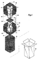
- a system for packaging explosive products for transportation is depicted and generally designated 10.
- the explosive products are shaped charges 12.
- Each shaped charge 12 has a generally cylindrically shaped housing 14 that is formed from steel or other suitable material.
- a quantity of high explosive powder (not pictured) is disposed within housing 14.
- the high explosive powder may typically be of the type sold under trade designations HMX, HNS, RDX, PYX and PETN.
- the high explosive powder is detonated using a detonating signal provided by a detonating cord.
- a booster explosive may also be used between detonating cord and high explosive powder to efficiently transfer the detonating signal from detonating cord to the high explosive powder.
- Each shaped charge 12 has a liner 16 disposed within housing 12 such that the high explosive substantially fills the volume between housing 12 and liner 16.
- Liner 16 may typically be formed by pressing, under very high pressure, a powdered metal mixture. Following the pressing process, liner 16 becomes a generally conically shaped rigid body that behaves substantially as a solid mass. Alternatively, liner 16 may be stamped from sheet metal or may have a generally parabolic or hemispherical shape.
- liner 16 Upon detonation, intentionally or unintentionally, the force of the detonation collapses liner 16 causing liner 16 to be ejected from housing 12 in the form of a jet traveling at very high velocity toward, for example, a well casing. In this scenario, the jet penetrates the well casing, the cement and the formation, thereby forming the perforations.
- jet spoilers 20 Each jet spoiler 20 is placed within the cavity formed within shaped charge 12 and defined by liner 16.
- the shape of jet spoilers 20 is preferably substantially the shape of the cavity such that each jet spoiler 20 may be disposed with a housing 14 and in substantial contact with a liner 16.
- Jet spoilers 20 may be made from a metal or nonmetal, but nonmetals are preferable in order to eliminate potential fragment pieces.
- jet spoilers 20 may be constructed of a suitably dense material such as wood, plastic, foam, rubber, plaster, cement and the like. Ideally the material would be one that is environmentally friendly for easy disposal, lightweight to facilitate shipping and handling and economical.
- a suitably dense material such as wood, plastic, foam, rubber, plaster, cement and the like.
- the material would be one that is environmentally friendly for easy disposal, lightweight to facilitate shipping and handling and economical.
- biodegradable cardboard, balsa wood or compressed sawdust are suitable materials.
- shaped charges 12 are packaged together in accordance with the present invention.
- This orientation not only inhibits the formation of a jet in the initiated shaped charge 12 but also inhibits the initiation of the opposing shaped charge 12.
- shaped charges were placed in an opposing orientation based upon the principle that if one shaped charge initiates and begins to jet, as that jet penetrates the opposing shaped charge, the second shaped charge would initiate such that the resulting detonations from each shaped charge would disrupt the other shaped charge, thereby preventing any jet penetration.
- initiation of a shaped charge 12 with a jet spoiler 20 in place does not create a jet but instead one jet spoiler 20 is propelled against the opposing jet spoiler 20. As jetting does not occur, this corresponding impact load between two opposing shaped charges 12 with jet spoilers 20 is substantially lower than in the case without jet spoilers 20.
- a plurality of shielding panels is positioned between and around shaped charges 12. These shielding panels may be made of materials or layers of materials that are resistant to fragments such as wood, aluminum, corrugated cardboard, woven ballistic cloth and the like.
- an interlayer shielding panel 22 is disposed between opposing jet spoilers 20 of shaped charges 12.
- a top shielding panel 24 is disposed above the upper shaped charge 12 while a bottom shielding panel 26 is disposed below the lower shaped charge 12.
- a set of side shielding panels 28 is positioned around upper shaped charge 12.
- set of side shielding panels 30 is positioned around lower shaped charge 12.
- Each of the shielding panels 22, 24, 26, 28 and 30 prevents fragments of shaped charges 12 or jet spoilers 20 from being discharged in the event of an inadvertent initiation.
- each shielding panel is depicted as providing fragment protection in one direction
- multidirectional arrangements of shielding panels are also contemplated and considered within the scope of the present invention.
- a bidirectional shielding panel including two side shielding panels 28 that are attached together at right angles to one another or a tridirectional shielding panel including two side shielding panels 28 and top shielding panel 24 attached together at right angles is possible and provides appropriate fragment protection.
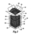
- Expandable bag 32 is made from a suitable fragment resistant fabric such a woven ballistic cloth. Expandable bag 32 may be rather loosely fitting when shaped charges 12 are placed therein, but is subsequently folded in a manner that allows it to be placed in transportation container 34, such as a corrugated cardboard box, as best seen in figure 2.
- transportation container 34 such as a corrugated cardboard box, as best seen in figure 2.
- the loose fitting nature of expandable bag 32 allows for gas expansion, in the event of an inadvertent initiation of a shaped charge 12. Expandable bag 32 is not permanently leak tight.
- expandable bag 32 the primary purpose of expandable bag 32 is to allow for expansion of the explosion gases while retaining all of the contents of its interior such as shaped charges 12, jet spoilers 20, shielding panels 22, 24, 26, 28 and 30, as well as any fragments of material that are created during an explosion.
- expandable bag 32 will expand in a manner similar to an automobile air bag, but will subsequently deflate since expandable bag 32 is not leak tight.
- transportation container 34 will likely be destroyed, but the effects of the explosion will remain localized within expandable bag 32 such that no hazard will exist to a first responder, such as a firefighter, or to passengers or crew on an aircraft.
- the present invention is also well-suited for transportation of other explosive products such as detonators, bidirectional boosters, igniters, cutters, explosive pellets and the like, albeit without the need for jet spoilers 20.
- other explosive products such as detonators, bidirectional boosters, igniters, cutters, explosive pellets and the like, albeit without the need for jet spoilers 20.
- the present invention will allow such explosive products to retain the U.N. 1.4S classification even under an unconfined Test 6(a), a single transportation vehicle will be able to transport more than one type of explosive product at the same time.
- shaped charges and their detonators may be transported from one location to another on the same transportation vehicle.
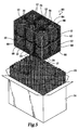
- a system for packaging explosive products for transportation is depicted and generally designated 40.
- the explosive products are again depicted as shaped charges 12.
- Each shaped charge 12 has a generally cylindrically shaped housing 14, a liner 16 and a quantity of high explosive powder that is disposed between housing 14 and liner 16.
- a jet spoilers 20 is positioned within the cavity formed within shaped charges 12 and defined by liners 16.
- shaped charges 12 are oriented in a layer arrangement with three shaped charges 12 in each layer. Shaped charges 12 are oriented within the layers such that jet spoilers 20 in adjacent layers oppose one another. This orientation not only inhibits the formation of a jet in the event of an initiation, but also inhibits the initiation of the opposing shaped charge 12 as one jet spoiler 20 would be propelled against the opposing jet spoiler 20.
- a plurality of shielding panels is positioned between and around shaped charges 12.
- An interlayer shielding panel 42 is disposed between opposing jet spoilers 20 of shaped charges 12 in the two layers.
- a top shielding panel 44 is disposed above the upper shaped charges 12 while a bottom shielding panel 46 is disposed below the lower shaped charges 12.
- a set of perimeter shielding panels 48 is positioned around shaped charge 12.
- a set of intralayer shielding panels 50 is disposed between adjacent shaped charges 12 within each layer.
- the combination of shaped charges 12, jet spoilers 20 and shielding panels 42, 44, 46, 48 and 50 is disposed within an expandable bag 52.
- Expandable bag 52 may be rather loosely fitting when shaped charges 12 are placed therein, but is subsequently folded in a manner that allows it to be placed in transportation container 54, as best seen in figure 4.
- each shaped charge 12 has a generally cylindrically shaped housing, a liner and a quantity of high explosive powder that is disposed between the housing and the liner.
- a jet spoiler is positioned within the cavity formed within each of the shaped charges 12 and defined by the liners.
- shaped charges 12 are oriented in a layer arrangement. Each layer includes a two by three array of shaped charges 12. Shaped charges 12 are oriented within the layers such that the associated jet spoilers positioned within shaped charges 12 in adjacent layers oppose one another.
- a plurality of shielding panels is positioned between and around shaped charges 12.
- An interlayer shielding panel 62 is disposed between opposing jet spoilers of shaped charges 12 in the two layers.
- a top shielding panel 64 is disposed above the upper array of shaped charges 12 while a bottom shielding panel 66 is disposed below the lower array of shaped charges 12.
- a set of perimeter shielding panels 68 is positioned around shaped charge 12.
- a set of intralayer shielding panels 70 is disposed between adjacent shaped charges 12 within each layer.
- the combination of shaped charges 12 including jet spoilers and shielding panels 62, 64, 66, 68 and 70 is disposed within an expandable bag 72.
- Expandable bag 72 may be rather loosely fitting when shaped charges 12 are placed therein, but is subsequently folded in a manner that allows it to be placed in transportation container 74.
- each shaped charge 12 has a generally cylindrically shaped housing, a liner and a quantity of high explosive powder that is disposed between the housing and the liner.
- a jet spoiler is positioned within the cavity formed within shaped charges 12 and defined by the liners.
- shaped charges 12 are oriented in a layer arrangement. Each of the four layers includes a two by three array of shaped charges 12. Shaped charges 12 in the top two layers are oriented such that the associated jet spoilers positioned therein oppose one another. Likewise, shaped charges 12 in the bottom two layers are oriented such that the associated jet spoilers positioned therein oppose one another.
- a plurality of shielding panels is positioned between and around shaped charges 12.
- Interlayer shielding panels 82 are disposed between opposing jet spoilers of shaped charges 12 in the top two and bottom two layers.
- an interlayer shielding panels 84 is disposed between the top two and bottom two layers of shaped charges 12.
- a top shielding panel 86 is disposed above the top layer of shaped charges 12 while a bottom shielding panel 88 is disposed below the bottom layer of shaped charges 12.
- a set of perimeter shielding panels 90 is positioned around shaped charge 12.
- a set of intralayer shielding panels 92 is disposed between adjacent shaped charges 12 within each layer.
- the combination of shaped charges 12 including jet spoilers and shielding panels 82, 84, 86, 88, 90 and 92 is disposed within an expandable bag 94.
- Expandable bag 94 is loosely fitting around shaped charges 12 and is subsequently folded in a manner that allows it to be placed in transportation container 96.
- this system provides an improved method for packaging explosive products for transportation.
- This system and method not only allow explosive products to pass the present confined Test 6(a), but also, an unconfined Test 6(a) such that the U.N. 1.4S classification will remain achievable.
- the use of the expandable bag of the present invention will allow many explosive products to retain the U.N. 1.4S classification if and when an unconfined Test 6(a) becomes the standard.
- use of the shielding panels of the present invention will allow many explosive products to retain the U.N. 1.4S classification under an unconfined Test 6(a).
- jet spoilers and opposing orientation of the shaped charges may be used in addition to or as an alternative to the expandable bag or the shielding panels to retain the U.N. 1.4S classification under an unconfined Test 6(a).
Landscapes
- Engineering & Computer Science (AREA)
- General Engineering & Computer Science (AREA)
- Buffer Packaging (AREA)
Abstract
Description
Claims (10)
- A method of packaging shaped charges for transportation comprising the steps of: positioning a jet spoiler proximate a liner of each shaped charge; orienting the shaped charges in first and second layers such that the jet spoilers positioned proximate the shaped charges in the first and second layers oppose one another; placing an expandable bag around the shaped charges; and enclosing the expandable bag in a transportation container.
- A method according to claim 1, further comprising the step of disposing a shielding panel between the first and second layers of the shaped charges;
- A method of packaging shaped charges for transportation comprising the steps of: positioning a jet spoiler proximate a liner of each shaped charge; orienting the shaped charges in first and second layers such that the jet spoilers positioned proximate the shaped charges in the first and second layers oppose one another; disposing a shielding panel between the first and second layers of the shaped charges; positioning perimeter shielding panels around the shaped charges; disposing interior shielding panels between adjacent shaped charges within each of the layers of shaped charges; and enclosing the shaped charges in a transportation container.
- A method according to claim 1, 2 or 3, wherein the step of positioning the jet spoiler proximate the liner of each of the shaped charges further comprises disposing the jet spoiler within a housing of the shaped charges and in substantial contact with the liner.
- A method according to any preceding claim, wherein the first layer further comprises a first array of shaped charges and wherein the second layer further comprises a second array of shaped charges.
- A method according to any preceding claim, further comprising the step of orienting the shaped charges in third and fourth layers such that the jet spoilers positioned proximate the shaped charges in the third and fourth layers oppose one another.
- A method for packaging explosive products for transportation comprising the steps of: placing at least two the explosive products in an expandable bag; and enclosing the expandable bag in a transportation container.
- A method according to claim 7, further comprising the step of disposing a shielding panel between the explosive products.
- A system for packaging shaped charges for transportation comprising: a jet spoiler positioned proximate a liner of each of the shaped charges, the shaped charges being oriented in first and second layers such that the jet spoilers positioned proximate the shaped charges in the first and second layers oppose one another; a shielding panel disposed between the shaped charges of the first and second layers; an expandable bag surrounding the of shaped charges; and a transportation container enclosing the expandable bag therein.
- A system for packaging explosive products for transportation comprising: an expandable bag for containing at least two explosive products; and a transportation container for enclosing the expandable bag therein.
Applications Claiming Priority (2)
| Application Number | Priority Date | Filing Date | Title |
|---|---|---|---|
| US09/764,699 US6454085B1 (en) | 2001-01-18 | 2001-01-18 | Method and system for packaging explosive products of transportation |
| US764699 | 2001-01-18 |
Publications (3)
| Publication Number | Publication Date |
|---|---|
| EP1225417A2 true EP1225417A2 (en) | 2002-07-24 |
| EP1225417A3 EP1225417A3 (en) | 2003-06-04 |
| EP1225417B1 EP1225417B1 (en) | 2007-02-21 |
Family
ID=25071500
Family Applications (1)
| Application Number | Title | Priority Date | Filing Date |
|---|---|---|---|
| EP02250229A Expired - Lifetime EP1225417B1 (en) | 2001-01-18 | 2002-01-14 | Method and system for packing explosive products for transportation |
Country Status (4)
| Country | Link |
|---|---|
| US (2) | US6454085B1 (en) |
| EP (1) | EP1225417B1 (en) |
| CA (1) | CA2368305C (en) |
| DE (1) | DE60218235T2 (en) |
Cited By (3)
| Publication number | Priority date | Publication date | Assignee | Title |
|---|---|---|---|---|
| WO2006031241A1 (en) * | 2004-01-12 | 2006-03-23 | Halliburton Energy Services, Inc. | Apparatus and method for packaging and shipping of high explosive content components |
| WO2010003858A1 (en) * | 2008-07-08 | 2010-01-14 | Dynaenergetics Gmbh & Co. Kg | Method for preparing hollow charges for transport, ensuring safe shipment |
| WO2012130854A1 (en) * | 2011-03-29 | 2012-10-04 | Dynaenergetics Gmbh & Co. Kg | Packing for hollow charges |
Families Citing this family (29)
| Publication number | Priority date | Publication date | Assignee | Title |
|---|---|---|---|---|
| US6454085B1 (en) * | 2001-01-18 | 2002-09-24 | Halliburton Energy Services, Inc. | Method and system for packaging explosive products of transportation |
| US6877415B2 (en) * | 2002-11-01 | 2005-04-12 | Legend Products Corporation | Individual premeasured charges with reduced moisture content and method of producing same |
| DE10255034A1 (en) * | 2002-11-19 | 2004-06-17 | Duropack Wellpappe Ansbach Gmbh | transport packaging |
| US7204183B2 (en) * | 2004-02-11 | 2007-04-17 | Salvatore Cirillo | Container for containing an explosion |
| US20060093804A1 (en) * | 2004-11-01 | 2006-05-04 | Weerth D E | Blast resistant liner for use in limited access enclosures |
| US20060183956A1 (en) * | 2004-12-17 | 2006-08-17 | Uxb | Method of transporting waste explosive materials |
| CA2545303A1 (en) * | 2005-09-06 | 2007-03-06 | Guy Gettle | Case for small explosive device |
| US8006622B2 (en) * | 2006-11-07 | 2011-08-30 | Orica Explosives Technology Pty Ltd | Protector for detonator, and method of use |
| US20090078420A1 (en) * | 2007-09-25 | 2009-03-26 | Schlumberger Technology Corporation | Perforator charge with a case containing a reactive material |
| GB2462804B (en) * | 2008-08-04 | 2013-01-23 | Edwards Ltd | Vacuum pump |
| US8210346B2 (en) * | 2009-03-23 | 2012-07-03 | Raytheon Company | Light weight and collapsible weapons container |
| RU2461794C1 (en) * | 2011-02-21 | 2012-09-20 | Закрытое акционерное общество "Барнаульский патронный завод" | Insert to pack cartridges of small arms |
| RU2461795C1 (en) * | 2011-04-18 | 2012-09-20 | Закрытое акционерное общество "Барнаульский патронный завод" | Method to feed cartridges to packaging box |
| RU2476818C1 (en) * | 2011-07-25 | 2013-02-27 | Закрытое акционерное общество "Барнаульский патронный завод" | Device to feed cartridges to packaging box |
| RU2488770C1 (en) * | 2011-12-29 | 2013-07-27 | Открытое акционерное общество "Конструкторское бюро приборостроения" | Packaging container for cartridges to shoulder launcher |
| WO2013162584A1 (en) * | 2012-04-26 | 2013-10-31 | Halliburton Energy Services, Inc. | Methods of applying a protective barrier to the liner of an explosive charge |
| CH707385B1 (en) * | 2012-12-21 | 2016-06-30 | Ruag Ammotec Ag | Transport means for ammunition, particularly small-caliber ammunition. |
| CN104176295B (en) * | 2014-08-13 | 2015-12-23 | 湖南工业大学 | A kind of Full autoamtic coloured pearl drum wrapping machine |
| US20160176609A1 (en) * | 2014-12-18 | 2016-06-23 | Keith Allan Currie | Packaging for Shipping of Hazardous Fluid Containers |
| US9829296B1 (en) | 2015-09-30 | 2017-11-28 | The United States Of America As Represented By The Secretary Of The Navy | Explosive container postioning saddle for munition demolition |
| WO2017097512A1 (en) * | 2015-12-07 | 2017-06-15 | Dynaenergetics Gmbh & Co. Kg | Shaped charge metal foam package |
| US20170176158A1 (en) * | 2015-12-18 | 2017-06-22 | Fernanda Di Biase | Container for containing explosive device and blast containing panel therefor |
| US12392211B2 (en) * | 2018-08-16 | 2025-08-19 | W.T. Bell International, Inc. | Explosive downhole tools having improved wellbore conveyance and debris properties, methods of using the explosive downhole tools in a wellbore, and explosive units for explosive column tools |
| US11781393B2 (en) * | 2018-08-16 | 2023-10-10 | James G. Rairigh | Explosive downhole tools having improved wellbore conveyance and debris properties, methods of using the explosive downhole tools in a wellbore, and explosive units for explosive column tools |
| WO2020142128A2 (en) * | 2018-10-10 | 2020-07-09 | Schlumberger Technology Corporation | Safe transport of shaped charges |
| CN111609770B (en) * | 2020-04-30 | 2022-09-13 | 南京理工大学 | Engineering detonator explosion-proof packaging box capable of guaranteeing storage and transportation safety and using method thereof |
| CN113911477A (en) * | 2021-09-03 | 2022-01-11 | 山东奇润机械设备有限公司 | Packaging production process of explosive blocks |
| US12221275B2 (en) | 2021-10-29 | 2025-02-11 | DynaEnergetics Europe GmbH | Mobile perforating bank unit and modular storage container |
| US12509953B2 (en) * | 2022-03-11 | 2025-12-30 | Shell Usa, Inc. | Method of creating a plurality of longitudinally separated circumferential dents in a wellbore tubular |
Family Cites Families (20)
| Publication number | Priority date | Publication date | Assignee | Title |
|---|---|---|---|---|
| US2352803A (en) * | 1940-10-16 | 1944-07-04 | Mossberg & Sons O F | Means for packing frangible articles |
| US2667968A (en) * | 1950-12-01 | 1954-02-02 | Twin Cities Container Corp | Packaging for frangible objects |
| US2954140A (en) * | 1958-01-29 | 1960-09-27 | Raytheon Co | Magnetic shielding |
| US3572499A (en) * | 1967-01-19 | 1971-03-30 | Custom Materials Inc | Conductive packaging material and container for explosives |
| US3999653A (en) * | 1975-03-11 | 1976-12-28 | The Dow Chemical Company | Packaging for hazardous liquids |
| US4286708A (en) * | 1979-08-21 | 1981-09-01 | The United States Of America As Represented By The Secretary Of The Navy | Module to prevent sympathetic detonations in munitions |
| US4306653A (en) * | 1980-03-03 | 1981-12-22 | Fales Gene T | Method and apparatus for packaging fragile articles |
| US4522871A (en) * | 1981-05-04 | 1985-06-11 | Armellino Jr Richard A | Ballistic material for flexible body armor and the like |
| US4682708A (en) * | 1981-10-15 | 1987-07-28 | Leggett & Platt, Incorporated | Insulated shipping container |
| US4664967A (en) * | 1986-04-21 | 1987-05-12 | The United States Of America As Represented By The Secretary Of The Army | Ballistic spall liner |
| DE3805478A1 (en) * | 1988-02-22 | 1989-08-31 | Deutsche Verpackungsmittel | Packing device for an explosive body |
| US4877131A (en) * | 1988-04-29 | 1989-10-31 | Spiro Patros | Firearm recovery bag |
| IL86763A (en) * | 1988-06-16 | 1993-07-08 | Yuval Fuchs | Portable collapsible shrapnel absprber |
| US5097945A (en) * | 1990-12-12 | 1992-03-24 | Schlumberger Technology Corporation | Method for safe packaging of shaped charges for transport |
| US5267652A (en) * | 1991-08-20 | 1993-12-07 | Carroll Hazen J | Shipping carton and dunnage having openings and flanges |
| US5450948A (en) * | 1994-04-14 | 1995-09-19 | Gtel Environmental Laboratories, Inc. | Container and package for transporting temperature sensitive samples |
| US5753850A (en) * | 1996-07-01 | 1998-05-19 | Western Atlas International, Inc. | Shaped charge for creating large perforations |
| US6253915B1 (en) * | 1999-07-20 | 2001-07-03 | Zuri Mesica | Protective firearm pouch |
| SE520378C2 (en) * | 1999-11-05 | 2003-07-01 | Bofors Carl Gustaf Ab | Methods and apparatus for an over-ignition of an RSV charge by fire or other means resulting in a spread to other nearby charges |
| US6454085B1 (en) * | 2001-01-18 | 2002-09-24 | Halliburton Energy Services, Inc. | Method and system for packaging explosive products of transportation |
-
2001
- 2001-01-18 US US09/764,699 patent/US6454085B1/en not_active Expired - Fee Related
-
2002
- 2002-01-14 DE DE60218235T patent/DE60218235T2/en not_active Expired - Lifetime
- 2002-01-14 EP EP02250229A patent/EP1225417B1/en not_active Expired - Lifetime
- 2002-01-17 CA CA002368305A patent/CA2368305C/en not_active Expired - Fee Related
- 2002-05-08 US US10/143,697 patent/US6629597B2/en not_active Expired - Lifetime
Cited By (4)
| Publication number | Priority date | Publication date | Assignee | Title |
|---|---|---|---|---|
| WO2006031241A1 (en) * | 2004-01-12 | 2006-03-23 | Halliburton Energy Services, Inc. | Apparatus and method for packaging and shipping of high explosive content components |
| US7416076B2 (en) | 2004-01-12 | 2008-08-26 | Halliburton Energy Services, Inc. | Apparatus and method for packaging and shipping of high explosive content components |
| WO2010003858A1 (en) * | 2008-07-08 | 2010-01-14 | Dynaenergetics Gmbh & Co. Kg | Method for preparing hollow charges for transport, ensuring safe shipment |
| WO2012130854A1 (en) * | 2011-03-29 | 2012-10-04 | Dynaenergetics Gmbh & Co. Kg | Packing for hollow charges |
Also Published As
| Publication number | Publication date |
|---|---|
| US6629597B2 (en) | 2003-10-07 |
| CA2368305A1 (en) | 2002-07-18 |
| US20020134054A1 (en) | 2002-09-26 |
| DE60218235D1 (en) | 2007-04-05 |
| US6454085B1 (en) | 2002-09-24 |
| EP1225417A3 (en) | 2003-06-04 |
| EP1225417B1 (en) | 2007-02-21 |
| US20020092793A1 (en) | 2002-07-18 |
| DE60218235T2 (en) | 2007-06-28 |
| CA2368305C (en) | 2006-10-10 |
Similar Documents
| Publication | Publication Date | Title |
|---|---|---|
| EP1225417B1 (en) | Method and system for packing explosive products for transportation | |
| US4248342A (en) | Blast suppressive shielding | |
| US6174587B1 (en) | Shock attenuation barrier | |
| US5390580A (en) | Lightweight explosive and fire resistant container | |
| US7416076B2 (en) | Apparatus and method for packaging and shipping of high explosive content components | |
| US4389947A (en) | Blast suppressive shielding | |
| US4325309A (en) | Blast suppressive shielding | |
| US5576511A (en) | Anti-explosion pads with steel mesh, slitted metal foil and expanded metal net | |
| PT1128875E (en) | Method and apparatus for containing and suppressing explosive detonations | |
| RU2333457C1 (en) | Method of ammunition burst | |
| US5494152A (en) | Detonator packaging system | |
| US5563364A (en) | Anti-explosion pads and their method of use | |
| US4347796A (en) | Blast suppressive shielding | |
| US20210123711A1 (en) | Shaped charge metal foam package | |
| US5873455A (en) | Nonpropagation casing | |
| US11781845B2 (en) | Safe transport of shaped charges | |
| US9945651B2 (en) | Packing for hollow charges | |
| AU661558B2 (en) | Explosives segregation method | |
| CA2238046C (en) | Detonator packaging | |
| CN117053641A (en) | A method for destroying used aerial bombs | |
| RINDNER et al. | Safety Design Considerations in Munition Plants Layout | |
| Dzury | Performance Oriented Packaging Testing of Safety and Arming Assemblies for the BLU 91/B and BLU 92/B Mines Packed 90 Per Wood Box | |
| MXPA99008800A (en) | Method and apparatus for containing and suppressing explosive detonations | |
| Merrill et al. | Ammonium Perchlorate Transportation Hazards Testing | |
| CN106672285A (en) | Gunpowder packaging method for safe transportation, gunpowder packet for safe transportation and transferring pack for safe transportation |
Legal Events
| Date | Code | Title | Description |
|---|---|---|---|
| PUAI | Public reference made under article 153(3) epc to a published international application that has entered the european phase |
Free format text: ORIGINAL CODE: 0009012 |
|
| AK | Designated contracting states |
Kind code of ref document: A2 Designated state(s): AT BE CH CY DE DK ES FI FR GB GR IE IT LI LU MC NL PT SE TR |
|
| AX | Request for extension of the european patent |
Free format text: AL;LT;LV;MK;RO;SI |
|
| PUAL | Search report despatched |
Free format text: ORIGINAL CODE: 0009013 |
|
| AK | Designated contracting states |
Designated state(s): AT BE CH CY DE DK ES FI FR GB GR IE IT LI LU MC NL PT SE TR |
|
| AX | Request for extension of the european patent |
Extension state: AL LT LV MK RO SI |
|
| RIC1 | Information provided on ipc code assigned before grant |
Ipc: 7F 42B 39/00 A Ipc: 7F 42B 39/14 B |
|
| 17P | Request for examination filed |
Effective date: 20030710 |
|
| AKX | Designation fees paid |
Designated state(s): DE FR GB NL |
|
| 17Q | First examination report despatched |
Effective date: 20040702 |
|
| GRAP | Despatch of communication of intention to grant a patent |
Free format text: ORIGINAL CODE: EPIDOSNIGR1 |
|
| GRAS | Grant fee paid |
Free format text: ORIGINAL CODE: EPIDOSNIGR3 |
|
| GRAA | (expected) grant |
Free format text: ORIGINAL CODE: 0009210 |
|
| AK | Designated contracting states |
Kind code of ref document: B1 Designated state(s): DE FR GB NL |
|
| PG25 | Lapsed in a contracting state [announced via postgrant information from national office to epo] |
Ref country code: NL Free format text: LAPSE BECAUSE OF FAILURE TO SUBMIT A TRANSLATION OF THE DESCRIPTION OR TO PAY THE FEE WITHIN THE PRESCRIBED TIME-LIMIT Effective date: 20070221 |
|
| REG | Reference to a national code |
Ref country code: GB Ref legal event code: FG4D |
|
| REF | Corresponds to: |
Ref document number: 60218235 Country of ref document: DE Date of ref document: 20070405 Kind code of ref document: P |
|
| NLV1 | Nl: lapsed or annulled due to failure to fulfill the requirements of art. 29p and 29m of the patents act | ||
| EN | Fr: translation not filed | ||
| PLBE | No opposition filed within time limit |
Free format text: ORIGINAL CODE: 0009261 |
|
| STAA | Information on the status of an ep patent application or granted ep patent |
Free format text: STATUS: NO OPPOSITION FILED WITHIN TIME LIMIT |
|
| 26N | No opposition filed |
Effective date: 20071122 |
|
| PG25 | Lapsed in a contracting state [announced via postgrant information from national office to epo] |
Ref country code: FR Free format text: LAPSE BECAUSE OF FAILURE TO SUBMIT A TRANSLATION OF THE DESCRIPTION OR TO PAY THE FEE WITHIN THE PRESCRIBED TIME-LIMIT Effective date: 20071012 |
|
| PG25 | Lapsed in a contracting state [announced via postgrant information from national office to epo] |
Ref country code: FR Free format text: LAPSE BECAUSE OF FAILURE TO SUBMIT A TRANSLATION OF THE DESCRIPTION OR TO PAY THE FEE WITHIN THE PRESCRIBED TIME-LIMIT Effective date: 20070221 |
|
| PGFP | Annual fee paid to national office [announced via postgrant information from national office to epo] |
Ref country code: GB Payment date: 20121228 Year of fee payment: 12 |
|
| PGFP | Annual fee paid to national office [announced via postgrant information from national office to epo] |
Ref country code: DE Payment date: 20130131 Year of fee payment: 12 |
|
| REG | Reference to a national code |
Ref country code: DE Ref legal event code: R082 Ref document number: 60218235 Country of ref document: DE Representative=s name: WEISSE, RENATE, DIPL.-PHYS. DR.-ING., DE |
|
| REG | Reference to a national code |
Ref country code: DE Ref legal event code: R119 Ref document number: 60218235 Country of ref document: DE |
|
| GBPC | Gb: european patent ceased through non-payment of renewal fee |
Effective date: 20140114 |
|
| PG25 | Lapsed in a contracting state [announced via postgrant information from national office to epo] |
Ref country code: DE Free format text: LAPSE BECAUSE OF NON-PAYMENT OF DUE FEES Effective date: 20140801 |
|
| REG | Reference to a national code |
Ref country code: DE Ref legal event code: R119 Ref document number: 60218235 Country of ref document: DE Effective date: 20140801 |
|
| PG25 | Lapsed in a contracting state [announced via postgrant information from national office to epo] |
Ref country code: GB Free format text: LAPSE BECAUSE OF NON-PAYMENT OF DUE FEES Effective date: 20140114 |