EP1225342A1 - Laufradsystem für Pumpen - Google Patents
Laufradsystem für Pumpen Download PDFInfo
- Publication number
- EP1225342A1 EP1225342A1 EP02000423A EP02000423A EP1225342A1 EP 1225342 A1 EP1225342 A1 EP 1225342A1 EP 02000423 A EP02000423 A EP 02000423A EP 02000423 A EP02000423 A EP 02000423A EP 1225342 A1 EP1225342 A1 EP 1225342A1
- Authority
- EP
- European Patent Office
- Prior art keywords
- impeller
- drive shaft
- compensation unit
- nut
- impeller system
- Prior art date
- Legal status (The legal status is an assumption and is not a legal conclusion. Google has not performed a legal analysis and makes no representation as to the accuracy of the status listed.)
- Granted
Links
- 239000004809 Teflon Substances 0.000 claims abstract description 6
- 229920006362 Teflon® Polymers 0.000 claims abstract description 6
- GWEVSGVZZGPLCZ-UHFFFAOYSA-N Titan oxide Chemical compound O=[Ti]=O GWEVSGVZZGPLCZ-UHFFFAOYSA-N 0.000 claims abstract description 6
- 239000000945 filler Substances 0.000 claims abstract description 5
- OKTJSMMVPCPJKN-UHFFFAOYSA-N Carbon Chemical compound [C] OKTJSMMVPCPJKN-UHFFFAOYSA-N 0.000 claims abstract description 3
- 239000010439 graphite Substances 0.000 claims abstract description 3
- 229910002804 graphite Inorganic materials 0.000 claims abstract description 3
- 239000004408 titanium dioxide Substances 0.000 claims abstract description 3
- 239000000126 substance Substances 0.000 claims description 4
- 229910010293 ceramic material Inorganic materials 0.000 claims description 3
- 229920001971 elastomer Polymers 0.000 claims description 3
- 239000000806 elastomer Substances 0.000 claims description 3
- 239000011521 glass Substances 0.000 claims description 3
- 239000002245 particle Substances 0.000 claims description 3
- -1 chalk Chemical compound 0.000 claims description 2
- 239000007788 liquid Substances 0.000 claims description 2
- 238000007789 sealing Methods 0.000 claims description 2
- HBMJWWWQQXIZIP-UHFFFAOYSA-N silicon carbide Chemical compound [Si+]#[C-] HBMJWWWQQXIZIP-UHFFFAOYSA-N 0.000 claims description 2
- 229910010271 silicon carbide Inorganic materials 0.000 claims description 2
- 239000000454 talc Substances 0.000 claims description 2
- 229910052623 talc Inorganic materials 0.000 claims description 2
- 239000000919 ceramic Substances 0.000 abstract description 3
- 238000005728 strengthening Methods 0.000 abstract 1
- QAOWNCQODCNURD-UHFFFAOYSA-N Sulfuric acid Chemical compound OS(O)(=O)=O QAOWNCQODCNURD-UHFFFAOYSA-N 0.000 description 6
- 238000012423 maintenance Methods 0.000 description 2
- 229920001343 polytetrafluoroethylene Polymers 0.000 description 2
- 239000004810 polytetrafluoroethylene Substances 0.000 description 2
- 238000005299 abrasion Methods 0.000 description 1
- 239000002253 acid Substances 0.000 description 1
- 210000001520 comb Anatomy 0.000 description 1
- 238000010924 continuous production Methods 0.000 description 1
- 239000000463 material Substances 0.000 description 1
- 239000007769 metal material Substances 0.000 description 1
- 238000000034 method Methods 0.000 description 1
- 238000011084 recovery Methods 0.000 description 1
Images

Classifications
-
- F—MECHANICAL ENGINEERING; LIGHTING; HEATING; WEAPONS; BLASTING
- F04—POSITIVE - DISPLACEMENT MACHINES FOR LIQUIDS; PUMPS FOR LIQUIDS OR ELASTIC FLUIDS
- F04D—NON-POSITIVE-DISPLACEMENT PUMPS
- F04D29/00—Details, component parts, or accessories
- F04D29/02—Selection of particular materials
- F04D29/026—Selection of particular materials especially adapted for liquid pumps
-
- F—MECHANICAL ENGINEERING; LIGHTING; HEATING; WEAPONS; BLASTING
- F04—POSITIVE - DISPLACEMENT MACHINES FOR LIQUIDS; PUMPS FOR LIQUIDS OR ELASTIC FLUIDS
- F04D—NON-POSITIVE-DISPLACEMENT PUMPS
- F04D29/00—Details, component parts, or accessories
- F04D29/18—Rotors
- F04D29/20—Mounting rotors on shafts
-
- F—MECHANICAL ENGINEERING; LIGHTING; HEATING; WEAPONS; BLASTING
- F04—POSITIVE - DISPLACEMENT MACHINES FOR LIQUIDS; PUMPS FOR LIQUIDS OR ELASTIC FLUIDS
- F04D—NON-POSITIVE-DISPLACEMENT PUMPS
- F04D7/00—Pumps adapted for handling specific fluids, e.g. by selection of specific materials for pumps or pump parts
- F04D7/02—Pumps adapted for handling specific fluids, e.g. by selection of specific materials for pumps or pump parts of centrifugal type
- F04D7/06—Pumps adapted for handling specific fluids, e.g. by selection of specific materials for pumps or pump parts of centrifugal type the fluids being hot or corrosive, e.g. liquid metals
- F04D7/065—Pumps adapted for handling specific fluids, e.g. by selection of specific materials for pumps or pump parts of centrifugal type the fluids being hot or corrosive, e.g. liquid metals for liquid metal
-
- F—MECHANICAL ENGINEERING; LIGHTING; HEATING; WEAPONS; BLASTING
- F05—INDEXING SCHEMES RELATING TO ENGINES OR PUMPS IN VARIOUS SUBCLASSES OF CLASSES F01-F04
- F05D—INDEXING SCHEME FOR ASPECTS RELATING TO NON-POSITIVE-DISPLACEMENT MACHINES OR ENGINES, GAS-TURBINES OR JET-PROPULSION PLANTS
- F05D2260/00—Function
- F05D2260/95—Preventing corrosion
-
- F—MECHANICAL ENGINEERING; LIGHTING; HEATING; WEAPONS; BLASTING
- F05—INDEXING SCHEMES RELATING TO ENGINES OR PUMPS IN VARIOUS SUBCLASSES OF CLASSES F01-F04
- F05D—INDEXING SCHEME FOR ASPECTS RELATING TO NON-POSITIVE-DISPLACEMENT MACHINES OR ENGINES, GAS-TURBINES OR JET-PROPULSION PLANTS
- F05D2300/00—Materials; Properties thereof
- F05D2300/40—Organic materials
- F05D2300/43—Synthetic polymers, e.g. plastics; Rubber
- F05D2300/432—PTFE [PolyTetraFluorEthylene]
-
- F—MECHANICAL ENGINEERING; LIGHTING; HEATING; WEAPONS; BLASTING
- F05—INDEXING SCHEMES RELATING TO ENGINES OR PUMPS IN VARIOUS SUBCLASSES OF CLASSES F01-F04
- F05D—INDEXING SCHEME FOR ASPECTS RELATING TO NON-POSITIVE-DISPLACEMENT MACHINES OR ENGINES, GAS-TURBINES OR JET-PROPULSION PLANTS
- F05D2300/00—Materials; Properties thereof
- F05D2300/60—Properties or characteristics given to material by treatment or manufacturing
- F05D2300/615—Filler
Definitions
- the invention relates to an impeller system for pumps with a in a housing arranged drive shaft with an impeller for conveying liquid media connected is.
- Circulation pumps are e.g. B. in the chemical industry to promote and / or Circulation of sometimes aggressive media used. So z. B. in one Thin acid recovery plant according to EP 0 476 744 B1 70% sulfuric acid circulated at a temperature of 120 ° C.
- the invention is based on the object of an impeller system for pumps to improve the preamble of claim 1 so that operational safety and availability is increased and the maintenance costs of the pumps are reduced are.
- this object is achieved in that the impeller consists of one ceramic material and that the impeller on a compensation unit postponed to absorb the thermal expansion.
- Ceramic impellers are extremely unaffected by aggressive (corrosive and abrasive) media such.
- B. sulfuric acid, making their lifespan essential is longer than with impellers made of metallic materials.
- the invention proposes that the impeller on a compensation unit is postponed to absorb the thermal expansion. hereby the different thermal expansion is absorbed so that it is too no dangerous tensions can arise.
- the compensation unit is a sleeve with an outer Kammprofile. The impeller is then slid onto this sleeve.
- the Compensation unit is expedient for a better hold on a socket, such as B. applied a gunmetal bushing.
- the compensation unit is made of Teflon (PTFE).
- the comb profile of the compensation unit is preferably perpendicular to the longitudinal axis the drive shaft inclined so that the individual combs fold can.
- Teflon is advantageously used strength-increasing fillers added.
- These fillers can z. B. consist of one or more of the following substances: graphite, Talc, chalk, titanium dioxide, silicon carbide, glass particles. Glass particles have become proven to be particularly efficient.
- the drive shaft is preferably a one-piece hollow shaft.
- the impeller is in preferred embodiment via an axially the impeller and the drive shaft protruding expansion screw via an impeller nut at the front end the impeller and a lock nut on the drive end of the drive shaft non-positively connected to the drive shaft.
- the impeller nut advantageously covers the front end of the impeller almost completely.
- Each between the impeller nut and the impeller and the impeller and The drive shaft is a flat gasket for transmitting the torque and sealing, preferably arranged an elastomer flat seal.
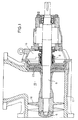
- Fig. 1 shows more schematically the essential elements of a circulation pump according to the prior art for aggressive media, such.
- the reference number 17 denotes a pump housing in which an impeller 18 is arranged for circulating the medium.
- Impeller 18 is pushed directly onto the drive shaft 6 and with a Impeller nut 5 attached.
- Impeller 18 and drive shaft 6 are made of a metallic Made of material.
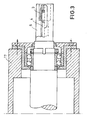
- Fig. 2 shows an impeller system according to the invention as a cross section through the front end of the drive shaft 6 and Fig. 3 by the drive end the drive shaft 6 in the pump housing 17th
- a one-piece hollow bore shaft 6b runs through the entire pump. On her a shaft sleeve 6a is attached. Shaft 6b and shaft sleeve 6a are in this Registration is often referred to as drive shaft 6 for the sake of simplicity.
- Impeller 18 At the front end of the drive shaft 6, an impeller 18 is attached.
- This Impeller 18 according to the invention consists of a ceramic material.
- Expansion screw 4 which has an impeller nut at its front end 5 and at its drive end (see Fig. 3) has a lock nut 3.
- the impeller nut 5 covers the front End of the impeller 18 almost completely.
- the impeller nut 5 is via a threaded adapter 1 and an anti-rotation device 9 attached to the expansion screw 4.
- an anti-rotation device 9 attached to the expansion screw 4.
- the reference numeral 11 is the Denoted longitudinal axis of the drive shaft 6.
- This Compensation unit 2 consists of a sleeve made of Teflon (PTFE) with a outer comb profile 10.
- the compensation unit 2 is held by a Gunmetal bushing 12, onto which the compensation unit 2 is pushed.
- the Comb profile 10 of the compensation unit 2 is perpendicular to the longitudinal axis 11 of the Drive shaft 6 slightly inclined, d. H. for the radial expansion of the impeller 18.
- This comb profile 10 absorbs thermal expansion.
- the impeller 18 with the gunmetal bushing 12 is on the expansion screw 4 pushed and the expansion screw 4 into the drive shaft 6 or the shaft 6b is plugged in until the impeller 18 with the compensation unit 2 is arranged between the impeller nut 5 and the drive shaft 6. Subsequently the expansion screw 4 at the drive end of the drive shaft 6 via the lock nut 3 z. B. anchored using a torque wrench.
- This impeller system according to the invention has been in operation for many years proven to be extremely reliable and low-maintenance.
Landscapes
- Engineering & Computer Science (AREA)
- Mechanical Engineering (AREA)
- General Engineering & Computer Science (AREA)
- Structures Of Non-Positive Displacement Pumps (AREA)
Abstract
Description
- sehr hohe chemische Beständigkeit
- hohe Abrasionsfestigkeit
- bei hohen Temperaturen einsetzbar
- einsetzbar bei hohen Antriebsleistungen
- kraftschlüssige Verbindung des Laufrades mit der Antriebswelle.
- Fig. 1
- eine Pumpe nach dem Stand der Technik im Querschnitt,
- Fig.2
- ein erfindungsgemäßes Laufradsystem als Querschnitt durch das stirnseitige Ende und
- Fig. 3
- durch das antriebsseitige Ende der Antriebswelle.
Claims (11)
- Laufradsystem für Pumpen mit einer in einem Gehäuse (17) angeordneten Antriebswelle (6), die mit einem Laufrad (18) zum Fördern flüssiger Medien verbunden ist, dadurch gekennzeichnet, dass das Laufrad (18) aus einem keramischen Werkstoff besteht und dass das Laufrad (18) auf einer Kompensationseinheit (2) zur Aufnahme der Wärmedehnung aufgeschoben ist.
- Laufradsystem nach Anspruch 1, dadurch gekennzeichnet, dass die Kompensationseinheit (2) eine Hülse mit äußerem Kammprofil (10) ist.
- Laufradsystem nach Anspruch 2, dadurch gekennzeichnet, dass das Kammprofil (10) senkrecht zur Längsachse (11) der Antriebswelle (6) eine Neigung aufweist.
- Laufradsystem nach einem der Ansprüche 1 bis 3, dadurch gekennzeichnet, dass die Kompensationseinheit (2) aus Teflon hergestellt ist.
- Laufradsystem nach einem der Ansprüche 1 bis 4, dadurch gekennzeichnet, dass die Kompensationseinheit (2) auf eine Buchse, insbesondere Rotgussbuchse (12) aufgebracht ist.
- Laufradsystem nach Anspruch 4, dadurch gekennzeichnet, dass dem Teflon der Kompensationseinheit (2) festigkeitserhöhende Füllstoffe zugemischt sind.
- Laufradsystem nach Anspruch 6, dadurch gekennzeichnet, dass die Füllstoffe aus einem oder mehreren der nachfolgenden Stoffe bestehen: Graphit, Talkum, Kreide, Titandioxid, Siliziumkarbid, Glaspartikel.
- Laufradsystem nach einem der Ansprüche 1 bis 7, dadurch gekennzeichnet, dass die Antriebswelle (6) eine einstückige hohle Welle (6b) ist.
- Laufradsystem nach einem der Ansrüche 1 bis 8, dadurch gekennzeichnet, dass das Laufrad (18) über eine das Laufrad (18) und die Antriebswelle (6) axial durchragende Dehnschraube (4) über eine Laufradmutter (5) am stirnseitigen Ende des Laufrades (18) und einer Kontermutter (3) am antriebsseitigen Ende der Antriebswelle (6) mit der Antriebswelle (6) kraftschlüssig verbunden ist.
- Laufradsystem nach Anspruch 9, dadurch gekennzeichnet, dass die Laufradmutter (5) das stirnseitige Ende des Laufrades (18) nahezu vollständig abdeckt.
- Laufradsystem nach Anspruch 9 oder 10, dadurch gekennzeichnet, dass jeweils zwischen der Laufradmutter (5) und dem Laufrad (18) und dem Laufrad (18) und der Antriebswelle (6) bzw. der Wellenhülse (6a) zur Übertragung des Drehmomentes und Abdichtung eine Flachdichtung (7), bevorzugt Elastomerflachdichtung angeordnet ist.
Applications Claiming Priority (2)
| Application Number | Priority Date | Filing Date | Title |
|---|---|---|---|
| DE10102104A DE10102104A1 (de) | 2001-01-18 | 2001-01-18 | Laufradsystem für Pumpen |
| DE10102104 | 2001-01-18 |
Publications (2)
| Publication Number | Publication Date |
|---|---|
| EP1225342A1 true EP1225342A1 (de) | 2002-07-24 |
| EP1225342B1 EP1225342B1 (de) | 2010-05-05 |
Family
ID=7670953
Family Applications (1)
| Application Number | Title | Priority Date | Filing Date |
|---|---|---|---|
| EP02000423A Expired - Lifetime EP1225342B1 (de) | 2001-01-18 | 2002-01-08 | Laufradsystem für Pumpen |
Country Status (4)
| Country | Link |
|---|---|
| EP (1) | EP1225342B1 (de) |
| AT (1) | ATE467052T1 (de) |
| DE (2) | DE10102104A1 (de) |
| ES (1) | ES2345762T3 (de) |
Families Citing this family (1)
| Publication number | Priority date | Publication date | Assignee | Title |
|---|---|---|---|---|
| RU2293884C1 (ru) * | 2005-07-26 | 2007-02-20 | Центральное конструкторское бюро машиностроения | Узел крепления рабочего колеса насоса на валу |
Citations (4)
| Publication number | Priority date | Publication date | Assignee | Title |
|---|---|---|---|---|
| US2433589A (en) * | 1939-05-25 | 1947-12-30 | Nash Engineering Co | Pump |
| US3255702A (en) | 1964-02-27 | 1966-06-14 | Molten Metal Systems Inc | Hot liquid metal pumps |
| US5249869A (en) * | 1991-05-21 | 1993-10-05 | Sundstrand Corporation | Preloaded assembly with thermal compensation |
| EP0476744B1 (de) | 1990-09-20 | 1995-04-05 | METALLGESELLSCHAFT Aktiengesellschaft | Verfahren zur Aufkonzentrierung von Dünnsäure in einer dreistufigen Vakuumzwangsumlaufverdampferanlage |
Family Cites Families (2)
| Publication number | Priority date | Publication date | Assignee | Title |
|---|---|---|---|---|
| DE3738081A1 (de) * | 1987-11-10 | 1989-05-18 | Rheinhuette Vorm Ludwig Beck G | Verbindung fuer werkstoffe unterschiedlicher waermeausdehnung |
| DE4336687C2 (de) * | 1992-10-27 | 2001-12-06 | Piller Industrieventilatoren G | Rotoreinheit |
-
2001
- 2001-01-18 DE DE10102104A patent/DE10102104A1/de not_active Withdrawn
-
2002
- 2002-01-08 EP EP02000423A patent/EP1225342B1/de not_active Expired - Lifetime
- 2002-01-08 ES ES02000423T patent/ES2345762T3/es not_active Expired - Lifetime
- 2002-01-08 DE DE50214406T patent/DE50214406D1/de not_active Expired - Lifetime
- 2002-01-08 AT AT02000423T patent/ATE467052T1/de not_active IP Right Cessation
Patent Citations (4)
| Publication number | Priority date | Publication date | Assignee | Title |
|---|---|---|---|---|
| US2433589A (en) * | 1939-05-25 | 1947-12-30 | Nash Engineering Co | Pump |
| US3255702A (en) | 1964-02-27 | 1966-06-14 | Molten Metal Systems Inc | Hot liquid metal pumps |
| EP0476744B1 (de) | 1990-09-20 | 1995-04-05 | METALLGESELLSCHAFT Aktiengesellschaft | Verfahren zur Aufkonzentrierung von Dünnsäure in einer dreistufigen Vakuumzwangsumlaufverdampferanlage |
| US5249869A (en) * | 1991-05-21 | 1993-10-05 | Sundstrand Corporation | Preloaded assembly with thermal compensation |
Also Published As
| Publication number | Publication date |
|---|---|
| DE50214406D1 (de) | 2010-06-17 |
| EP1225342B1 (de) | 2010-05-05 |
| DE10102104A1 (de) | 2002-07-25 |
| ES2345762T3 (es) | 2010-10-01 |
| ATE467052T1 (de) | 2010-05-15 |
Similar Documents
| Publication | Publication Date | Title |
|---|---|---|
| EP1071896B1 (de) | Dichtungselement für eine gleitringdichtungsanordnung | |
| CN115339141A (zh) | 具有过滤板的螺杆压力机 | |
| DE2850394A1 (de) | Verfahren zur abdichtung einer welle in einer gehaeusebohrung und wellendichtung dafuer | |
| EP2171284A1 (de) | Flüssigkeitspumpe | |
| EP1225342B1 (de) | Laufradsystem für Pumpen | |
| DE2604002C3 (de) | Schlauchpumpe | |
| EP0108186B1 (de) | Wellendichtring | |
| WO2003101583A1 (de) | Vorrichtung zum filtern von unter einem hohen druck geförderten fluiden | |
| DE102019005366A1 (de) | Exzenterschneckenpumpe | |
| EP0548022A1 (de) | Vorrichtung zum Mischen und/oder Kneten von Materialien | |
| EP1225379B1 (de) | Dichtungsbalgsystem für rotierende Wellen | |
| DE4308755A1 (de) | Klauenkupplung für eine Schraubenpumpe und Verfahren zu ihrer Herstellung | |
| DE3049836C2 (de) | Bohrlochsohlenantrieb für Bohrwerkzeuge | |
| EP2397716A2 (de) | Elastische kupplung | |
| DE10156228A1 (de) | Rotor einer Expansionsturbine für Tieftemperaturanwendungen | |
| EP0764783A1 (de) | Exzenterschneckenpumpe | |
| EP1318312A2 (de) | Wellenabdichtungssystem für rotierende Wellen an Pumpen | |
| DE3322933A1 (de) | Wasserpumpe als vorsatzgeraet fuer handbohrmaschinen | |
| DE102025106097B3 (de) | Mahlbehälter einer rührwerksmühle und rührwerksmühle mit einem solchen mahlbehälter | |
| DE2550034C2 (de) | Kreiselpumpe | |
| DE202013003630U1 (de) | Magnetgekuppelte Pumpenvorrichtung mit hoher Beständigkeit | |
| DE20109452U1 (de) | Anlage zur biologischen Abwasserbehandlung-Rotationstauchkörper | |
| DE102018208571B4 (de) | Spindelantrieb und Aktuator einer Lenkung mit Spindelantrieb | |
| DE102013201902A1 (de) | Kreiselpumpe und Baureihe von Kreiselpumpen | |
| DE202022002669U1 (de) | Schraubenkopf Außensechskrund & Außenachtkrund (Außenantrieb), das dazugehörige Schraubenantriebssystem & Schraubenmuttern |
Legal Events
| Date | Code | Title | Description |
|---|---|---|---|
| PUAI | Public reference made under article 153(3) epc to a published international application that has entered the european phase |
Free format text: ORIGINAL CODE: 0009012 |
|
| AK | Designated contracting states |
Kind code of ref document: A1 Designated state(s): AT BE CH CY DE DK ES FI FR GB GR IE IT LI LU MC NL PT SE TR |
|
| AX | Request for extension of the european patent |
Free format text: AL;LT;LV;MK;RO;SI |
|
| 17P | Request for examination filed |
Effective date: 20030124 |
|
| AKX | Designation fees paid |
Designated state(s): AT BE CH CY DE DK ES FI FR GB GR IE IT LI LU MC NL PT SE TR |
|
| 17Q | First examination report despatched |
Effective date: 20080515 |
|
| GRAP | Despatch of communication of intention to grant a patent |
Free format text: ORIGINAL CODE: EPIDOSNIGR1 |
|
| RIC1 | Information provided on ipc code assigned before grant |
Ipc: F04D 29/20 20060101AFI20091104BHEP |
|
| GRAS | Grant fee paid |
Free format text: ORIGINAL CODE: EPIDOSNIGR3 |
|
| GRAA | (expected) grant |
Free format text: ORIGINAL CODE: 0009210 |
|
| AK | Designated contracting states |
Kind code of ref document: B1 Designated state(s): AT BE CH CY DE DK ES FI FR GB GR IE IT LI LU MC NL PT SE TR |
|
| REG | Reference to a national code |
Ref country code: GB Ref legal event code: FG4D Free format text: NOT ENGLISH |
|
| REG | Reference to a national code |
Ref country code: CH Ref legal event code: EP |
|
| REG | Reference to a national code |
Ref country code: IE Ref legal event code: FG4D Free format text: LANGUAGE OF EP DOCUMENT: GERMAN |
|
| REF | Corresponds to: |
Ref document number: 50214406 Country of ref document: DE Date of ref document: 20100617 Kind code of ref document: P |
|
| REG | Reference to a national code |
Ref country code: NL Ref legal event code: VDEP Effective date: 20100505 |
|
| REG | Reference to a national code |
Ref country code: ES Ref legal event code: FG2A Ref document number: 2345762 Country of ref document: ES Kind code of ref document: T3 |
|
| PG25 | Lapsed in a contracting state [announced via postgrant information from national office to epo] |
Ref country code: SE Free format text: LAPSE BECAUSE OF FAILURE TO SUBMIT A TRANSLATION OF THE DESCRIPTION OR TO PAY THE FEE WITHIN THE PRESCRIBED TIME-LIMIT Effective date: 20100505 Ref country code: NL Free format text: LAPSE BECAUSE OF FAILURE TO SUBMIT A TRANSLATION OF THE DESCRIPTION OR TO PAY THE FEE WITHIN THE PRESCRIBED TIME-LIMIT Effective date: 20100505 |
|
| PG25 | Lapsed in a contracting state [announced via postgrant information from national office to epo] |
Ref country code: FI Free format text: LAPSE BECAUSE OF FAILURE TO SUBMIT A TRANSLATION OF THE DESCRIPTION OR TO PAY THE FEE WITHIN THE PRESCRIBED TIME-LIMIT Effective date: 20100505 |
|
| REG | Reference to a national code |
Ref country code: IE Ref legal event code: FD4D |
|
| PG25 | Lapsed in a contracting state [announced via postgrant information from national office to epo] |
Ref country code: CY Free format text: LAPSE BECAUSE OF FAILURE TO SUBMIT A TRANSLATION OF THE DESCRIPTION OR TO PAY THE FEE WITHIN THE PRESCRIBED TIME-LIMIT Effective date: 20100505 Ref country code: GR Free format text: LAPSE BECAUSE OF FAILURE TO SUBMIT A TRANSLATION OF THE DESCRIPTION OR TO PAY THE FEE WITHIN THE PRESCRIBED TIME-LIMIT Effective date: 20100806 |
|
| PG25 | Lapsed in a contracting state [announced via postgrant information from national office to epo] |
Ref country code: IE Free format text: LAPSE BECAUSE OF FAILURE TO SUBMIT A TRANSLATION OF THE DESCRIPTION OR TO PAY THE FEE WITHIN THE PRESCRIBED TIME-LIMIT Effective date: 20100505 Ref country code: PT Free format text: LAPSE BECAUSE OF FAILURE TO SUBMIT A TRANSLATION OF THE DESCRIPTION OR TO PAY THE FEE WITHIN THE PRESCRIBED TIME-LIMIT Effective date: 20100906 Ref country code: DK Free format text: LAPSE BECAUSE OF FAILURE TO SUBMIT A TRANSLATION OF THE DESCRIPTION OR TO PAY THE FEE WITHIN THE PRESCRIBED TIME-LIMIT Effective date: 20100505 |
|
| PLBE | No opposition filed within time limit |
Free format text: ORIGINAL CODE: 0009261 |
|
| STAA | Information on the status of an ep patent application or granted ep patent |
Free format text: STATUS: NO OPPOSITION FILED WITHIN TIME LIMIT |
|
| PG25 | Lapsed in a contracting state [announced via postgrant information from national office to epo] |
Ref country code: IT Free format text: LAPSE BECAUSE OF FAILURE TO SUBMIT A TRANSLATION OF THE DESCRIPTION OR TO PAY THE FEE WITHIN THE PRESCRIBED TIME-LIMIT Effective date: 20100505 |
|
| 26N | No opposition filed |
Effective date: 20110208 |
|
| REG | Reference to a national code |
Ref country code: DE Ref legal event code: R097 Ref document number: 50214406 Country of ref document: DE Effective date: 20110207 |
|
| BERE | Be: lapsed |
Owner name: SACHTLEBEN CHEMIE G.M.B.H. Effective date: 20110131 |
|
| PG25 | Lapsed in a contracting state [announced via postgrant information from national office to epo] |
Ref country code: MC Free format text: LAPSE BECAUSE OF NON-PAYMENT OF DUE FEES Effective date: 20110131 |
|
| REG | Reference to a national code |
Ref country code: CH Ref legal event code: PL |
|
| GBPC | Gb: european patent ceased through non-payment of renewal fee |
Effective date: 20110108 |
|
| PG25 | Lapsed in a contracting state [announced via postgrant information from national office to epo] |
Ref country code: LI Free format text: LAPSE BECAUSE OF NON-PAYMENT OF DUE FEES Effective date: 20110131 Ref country code: CH Free format text: LAPSE BECAUSE OF NON-PAYMENT OF DUE FEES Effective date: 20110131 |
|
| PG25 | Lapsed in a contracting state [announced via postgrant information from national office to epo] |
Ref country code: GB Free format text: LAPSE BECAUSE OF NON-PAYMENT OF DUE FEES Effective date: 20110108 Ref country code: BE Free format text: LAPSE BECAUSE OF NON-PAYMENT OF DUE FEES Effective date: 20110131 |
|
| REG | Reference to a national code |
Ref country code: AT Ref legal event code: MM01 Ref document number: 467052 Country of ref document: AT Kind code of ref document: T Effective date: 20110108 |
|
| PG25 | Lapsed in a contracting state [announced via postgrant information from national office to epo] |
Ref country code: AT Free format text: LAPSE BECAUSE OF NON-PAYMENT OF DUE FEES Effective date: 20110108 |
|
| PG25 | Lapsed in a contracting state [announced via postgrant information from national office to epo] |
Ref country code: LU Free format text: LAPSE BECAUSE OF NON-PAYMENT OF DUE FEES Effective date: 20110108 |
|
| PG25 | Lapsed in a contracting state [announced via postgrant information from national office to epo] |
Ref country code: TR Free format text: LAPSE BECAUSE OF FAILURE TO SUBMIT A TRANSLATION OF THE DESCRIPTION OR TO PAY THE FEE WITHIN THE PRESCRIBED TIME-LIMIT Effective date: 20100505 |
|
| REG | Reference to a national code |
Ref country code: FR Ref legal event code: PLFP Year of fee payment: 14 |
|
| PGFP | Annual fee paid to national office [announced via postgrant information from national office to epo] |
Ref country code: ES Payment date: 20150115 Year of fee payment: 14 Ref country code: DE Payment date: 20150122 Year of fee payment: 14 |
|
| PGFP | Annual fee paid to national office [announced via postgrant information from national office to epo] |
Ref country code: FR Payment date: 20150122 Year of fee payment: 14 |
|
| REG | Reference to a national code |
Ref country code: DE Ref legal event code: R119 Ref document number: 50214406 Country of ref document: DE |
|
| REG | Reference to a national code |
Ref country code: FR Ref legal event code: ST Effective date: 20160930 |
|
| PG25 | Lapsed in a contracting state [announced via postgrant information from national office to epo] |
Ref country code: DE Free format text: LAPSE BECAUSE OF NON-PAYMENT OF DUE FEES Effective date: 20160802 |
|
| PG25 | Lapsed in a contracting state [announced via postgrant information from national office to epo] |
Ref country code: FR Free format text: LAPSE BECAUSE OF NON-PAYMENT OF DUE FEES Effective date: 20160201 |
|
| PG25 | Lapsed in a contracting state [announced via postgrant information from national office to epo] |
Ref country code: ES Free format text: LAPSE BECAUSE OF NON-PAYMENT OF DUE FEES Effective date: 20160109 |
|
| REG | Reference to a national code |
Ref country code: ES Ref legal event code: FD2A Effective date: 20181207 |