EP1225326B1 - Conduit obturation system, in particular for ramjet air conduits - Google Patents
Conduit obturation system, in particular for ramjet air conduits Download PDFInfo
- Publication number
- EP1225326B1 EP1225326B1 EP02290020A EP02290020A EP1225326B1 EP 1225326 B1 EP1225326 B1 EP 1225326B1 EP 02290020 A EP02290020 A EP 02290020A EP 02290020 A EP02290020 A EP 02290020A EP 1225326 B1 EP1225326 B1 EP 1225326B1
- Authority
- EP
- European Patent Office
- Prior art keywords
- orifice
- shut
- ramjet
- duct
- shutter
- Prior art date
- Legal status (The legal status is an assumption and is not a legal conclusion. Google has not performed a legal analysis and makes no representation as to the accuracy of the status listed.)
- Expired - Lifetime
Links
Images


Classifications
-
- F—MECHANICAL ENGINEERING; LIGHTING; HEATING; WEAPONS; BLASTING
- F02—COMBUSTION ENGINES; HOT-GAS OR COMBUSTION-PRODUCT ENGINE PLANTS
- F02K—JET-PROPULSION PLANTS
- F02K7/00—Plants in which the working fluid is used in a jet only, i.e. the plants not having a turbine or other engine driving a compressor or a ducted fan; Control thereof
- F02K7/10—Plants in which the working fluid is used in a jet only, i.e. the plants not having a turbine or other engine driving a compressor or a ducted fan; Control thereof characterised by having ram-action compression, i.e. aero-thermo-dynamic-ducts or ram-jet engines
- F02K7/18—Composite ram-jet/rocket engines
-
- Y—GENERAL TAGGING OF NEW TECHNOLOGICAL DEVELOPMENTS; GENERAL TAGGING OF CROSS-SECTIONAL TECHNOLOGIES SPANNING OVER SEVERAL SECTIONS OF THE IPC; TECHNICAL SUBJECTS COVERED BY FORMER USPC CROSS-REFERENCE ART COLLECTIONS [XRACs] AND DIGESTS
- Y02—TECHNOLOGIES OR APPLICATIONS FOR MITIGATION OR ADAPTATION AGAINST CLIMATE CHANGE
- Y02T—CLIMATE CHANGE MITIGATION TECHNOLOGIES RELATED TO TRANSPORTATION
- Y02T50/00—Aeronautics or air transport
- Y02T50/60—Efficient propulsion technologies, e.g. for aircraft
Definitions
- the present invention relates to a closure system for a leads. Although not exclusively, it concerns more particularly a shutter system for an orifice of an air introduction path in the combustion chamber of a ramjet.
- ramjets are essentially constituted by a combustion chamber, ending with an ejection nozzle and inside which are introduced liquid or gaseous fuel (obtainable from a solid fuel) and combustion air.
- This combustion air is introduced into said combustion chamber through at least one air introduction pathway, air, which captures air when said ramjet (or the aerial mobile which door) moves relative to the ambient air.
- Such dual-mode operation obliges to provide a closure system for, on the one hand, closing an orifice of said air introduction channel or windsock during the rocket operation, in order to prevent leakage, through said orifice, of gases generated by said consumable auxiliary propellant and, on the other hand, open said orifice of the air introduction channel or windsock for the operating in the ramjet itself.
- US-A-4,028,886 also discloses such a system.
- said shutter system is of simple construction and little expensive.
- the unlocking can be done very effectively, as will be discussed in more detail below.
- said striker means acts on a trap which is movable under the action of said striker means.
- said trap advantageously comprises an elastic buffer, to dampen the action of said striker means, which makes it possible to obtain a soft shock on the trap, such a soft shock allowing to preserve the corresponding amount of movement while protecting the trap and mechanical elements associated with it.
- the shutter system according to the invention further comprises a guide rectilinear guide for said projectile, rectilinear guide which is made under shape of a channel, one end of which is located opposite said means of projection and whose other end is directed towards said trap.
- said striker means comprises a pyrotechnic striker. It may be the striker itself, such as means of projection.
- said hood has a face external which is inclined relative to a predetermined predetermined direction a flow of fluid outside the conduit. This facilitates separation (or ejection) of the hood of said duct, when said hood is unlocked due to the action of said fluid flow on said inclined outer face.
- closure system according to the invention can be implemented on different types of ducts, including the opening or Unclogging must be performed in an operational environment. Moreover, he is able to withstand mechanical, thermal and vibratory stresses and very high electromagnetic.
- said closure system is remarkable in that in addition to the above-mentioned characteristics (concerning the actuating device and the shutter), said shutter closes the inlet orifice in the air introduction route, upstream of the latter in the direction flow of air in said air introduction path.
- the present invention also relates to a ramjet equipped with of a shutter system as mentioned above, and a missile comprising such a ramjet.
- Figure 1 shows schematically, in partial longitudinal section, a missile equipped with a ramjet of known type, whose tracks introduction of air are provided with shutters forming part of shutter according to the invention.
- FIG. 2 is a longitudinal sectional view of a shutter according to the invention.
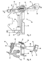
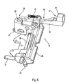
- Figures 3 and 5 are respectively plan and perspective of a locking device of a shutter system according to the invention.
- FIG. 4 is a section along the line IV-IV of FIG.
- FIG. 6 schematically shows, in partial longitudinal section, striker means of a closure system according to the invention.
- Figures 7 and 8 are perspective views of a hood according to the invention, shown respectively in profile and from above.
- the missile 1 comprises a body 3 containing, among other things, and usual expenses (which are not represented because they are not involved by the invention) and a fuel tank 4, intended for feeding the ramjet 2 and attached to the rear portion of said body 3.
- the ramjet 2 comprises a combustion chamber 5, terminating at the rear by an ejection nozzle 6 and connected, forwards, a plurality of air introduction ways, of the air-shaft type 7.
- the windsocks 7 are arranged at the periphery of the body 3 and are in solidarity with it. Each of them, towards the front, has an orifice 8 the air inlet and, towards the rear, opens into the front part of the combustion chamber 5 by an outlet 10 of air outlet of the sleeve 7.
- An elbow 11 is provided in each airfoil 7 to connect the part thereof attached to the outer wall of the body 3 to the orifice 10 corresponding to the inlet of the combustion chamber 5.
- a device 12 for fuel injection is provided in the vicinity of the front portion 9 of the combustion chamber 5 .
- the device 12 is controlled by a fuel supply and regulation device (not shown) carried by the body 3 and connected to the tank 4.
- a thermal protection coating 13 is provided on the walls internal combustion chamber 5.
- the operation of the missile 1 is as follows.
- the missile 1 is driven by a propellant consumable auxiliary 14 (for example a powder charge) housed at inside the combustion chamber 5.
- a propellant consumable auxiliary 14 for example a powder charge housed at inside the combustion chamber 5.
- the supply and regulating device feeds the fuel injection device 12 and the latter is ignited.
- the ramjet then enters into operation and takes over from the thruster 14 (which disappeared) to propel the missile 1.
- the locking device 19 comprises an unlocking mechanism 29 which includes a blade 30.
- This blade 30 is subjected to the action of a return spring 31 and is susceptible to be moved in the direction illustrated by an arrow B in FIG. act by one 32 of its ends on the clamping rod 26 to unlock it.
- Said blade 30 has at its other end 33 a trap 34 which is intended to cooperate with the striker means 21 of the actuating device 17.
- projection means 36 is made in the form of a pyrotechnic striker which has been partially shown a cord 37 making it possible to transmit the command (electric firing), to control the trigger said striker 36.
- Said striker means 21 further comprises a rectilinear guide 38 to guide the projectile 35, rectilinear guide which is made in the form of a channel 38, one end of which is opposite said projection means 36 and whose other end is directed towards the trap 34, which allows to optimize the accuracy of the projection and thus the effectiveness of the unlocking.
- said striker means act directly on the jaws 20 or via a mechanism different from that 26, 29 shown in Figures 3 to 5.
- said trap 34 also comprises an elastic buffer 39 shown in Figure 4, to dampen the shock during impact of the projectile 35 so as to obtain a "soft” impact, which makes it possible retain the corresponding momentum while protecting the trap 34, as well as the mechanical elements located near said trap 34.
- the hood 18, pyramidal shape has a face 40 which is inclined with respect to the flow E outside the missile 1. Thanks to the force exerted by this flow E on this face 40, the cover 18 is ejected off the sleeve to air 7, as soon as it is released from any mechanical stress on its face lower 18B, that is to say, as soon as the jaws 20 are unlocked.
- the shutter system 16 according to the invention and presented above works as follows.
- the shutter system 16 according to the invention is simple realization and operation and it is inexpensive and compact, especially in ramjet phase.
- the projectile 35 is not ejected (separately) out of the ramjet 2 when unlocking. Consequently, he there is no risk to the safety of persons or objects find in the near environment of the missile 1.
- said shutter system 16 according to the invention can be applied to other types of ducts, and not only to windsocks 7.
Landscapes
- Engineering & Computer Science (AREA)
- Chemical & Material Sciences (AREA)
- Combustion & Propulsion (AREA)
- Mechanical Engineering (AREA)
- General Engineering & Computer Science (AREA)
- Aiming, Guidance, Guns With A Light Source, Armor, Camouflage, And Targets (AREA)
- Portable Nailing Machines And Staplers (AREA)
- Pipe Accessories (AREA)
- Compressor (AREA)
- Exhaust Gas After Treatment (AREA)
- Lubrication Of Internal Combustion Engines (AREA)
- Testing Of Engines (AREA)
Abstract
Description
La présente invention concerne un système d'obturation pour un conduit. Bien que non exclusivement, elle concerne plus particulièrement un système d'obturation pour un orifice d'une voie d'introduction d'air dans la chambre de combustion d'un statoréacteur.The present invention relates to a closure system for a leads. Although not exclusively, it concerns more particularly a shutter system for an orifice of an air introduction path in the combustion chamber of a ramjet.
On sait que les statoréacteurs sont essentiellement constitués par une chambre de combustion, se terminant par une tuyère d'éjection et à l'intérieur de laquelle sont introduits du combustible liquide ou gazeux (pouvant être obtenu à partir d'un combustible solide) et de l'air de combustion. Cet air de combustion est introduit dans ladite chambre de combustion à travers au moins une voie d'introduction d'air, du type manche à air, qui capte de l'air lorsque ledit statoréacteur (ou le mobile aérien qui le porte) se déplace par rapport à l'air ambiant.It is known that ramjets are essentially constituted by a combustion chamber, ending with an ejection nozzle and inside which are introduced liquid or gaseous fuel (obtainable from a solid fuel) and combustion air. This combustion air is introduced into said combustion chamber through at least one air introduction pathway, air, which captures air when said ramjet (or the aerial mobile which door) moves relative to the ambient air.
Ainsi, le fonctionnement d'un statoréacteur nécessite la mise en vitesse préalable dudit statoréacteur par rapport audit air ambiant.Thus, the operation of a ramjet requires the implementation prior speed of said ramjet relative to said ambient air.
Pour ce faire, il est usuel, dans une phase initiale de fonctionnement correspondant à la mise en vitesse dudit statoréacteur, de faire fonctionner celui-ci en fusée, grâce à un propulseur auxiliaire consommable disposé dans ladite chambre de combustion, puis, lorsque ledit statoréacteur a atteint une vitesse prédéterminée et que ledit propulseur auxiliaire est complètement consumé, on passe en fonctionnement statoréacteur proprement dit, avec injection de combustible et d'air de combustion dans la chambre de combustion.To do this, it is usual, in an initial phase of operation corresponding to the setting speed of said ramjet, to operate this rocket, thanks to an auxiliary propellant consumable disposed in said combustion chamber, and then when said ramjet has reached a predetermined speed and that said auxiliary thruster is completely consumed, we go into operation ramjet proper, with fuel injection and combustion air in the combustion chamber.
Un tel fonctionnement bimode (mode fusée, puis mode statoréacteur) oblige à prévoir un système d'obturation pour, d'une part, obturer un orifice de ladite voie d'introduction d'air ou manche à air pendant le fonctionnement en fusée, afin d'éviter les fuites, à travers ledit orifice, des gaz engendrés par ledit propulseur auxiliaire consommable et, d'autre part, ouvrir ledit orifice de la voie d'introduction d'air ou manche à air pour le fonctionnement en statoréacteur proprement dit.Such dual-mode operation (rocket mode, then ramjet mode) obliges to provide a closure system for, on the one hand, closing an orifice of said air introduction channel or windsock during the rocket operation, in order to prevent leakage, through said orifice, of gases generated by said consumable auxiliary propellant and, on the other hand, open said orifice of the air introduction channel or windsock for the operating in the ramjet itself.
Il est connu (voir par exemple le document JP-03057867) d'utiliser comme système d'obturation une trappe basculante à ouverture commandée. Toutefois, dans ce cas, on doit généralement prévoir un système de commande particulièrement sophistiqué, évitant toute ouverture intempestive de la trappe, qui pourrait entraíner une mise à feu prématurée dudit propulseur auxiliaire consommable et, par suite, endommager le porteur (avion par exemple) d'un missile équipé dudit statoréacteur. De plus, surtout, cette trappe reste présente à bord du statoréacteur après l'ouverture de la voie d'introduction d'air, ce qui pose bien entendu des problèmes d'encombrement et entraíne la présence d'une masse parasite durant le fonctionnement statoréacteur.It is known (see for example JP-03057867) to use as a shutter system an opening tilting hatch ordered. However, in this case, a system must generally be particularly sophisticated control, avoiding any opening inadvertent trap, which could lead to premature firing of said consumable auxiliary propellant and, consequently, damage to the carrier (aircraft for example) a missile equipped with said ramjet. Moreover, especially, this hatch remains present on board the ramjet after the opening of the air introduction route, which of course poses congestion problems and causes the presence of a parasitic mass during ramjet operation.
Pour remédier au moins partiellement à ce dernier inconvénient, le document FR-2 474 594 décrit un système d'obturation pour un orifice d'introduction d'air de combustion dans la chambre de combustion d'un statoréacteur, qui comporte :
- un obturateur ou couvercle en verre qui obture complètement ledit orifice pendant la phase initiale ; et
- un dispositif de destruction, à savoir un dispositif de percussion mécanique, qui détruit cet obturateur en verre, avant le fonctionnement statoréacteur. Lors de cette destruction, l'obturateur en verre est décomposé en petits fragments. Comme l'orifice se trouve en aval de la manche à air et correspond à l'embouchure dans la chambre de combustion, ces fragments sont éjectés à l'extérieur, vers l'arrière, en passant par la chambre de combustion et la tuyère de poussée.
- a shutter or glass cover which completely closes said orifice during the initial phase; and
- a destruction device, namely a mechanical percussion device, which destroys this glass shutter, before the ramjet operation. During this destruction, the glass shutter is broken down into small fragments. As the orifice is downstream of the windsock and corresponds to the mouth in the combustion chamber, these fragments are ejected outside, towards the rear, through the combustion chamber and the nozzle of thrust.
Par conséquent, l'obturateur est complètement éliminé lors du fonctionnement statoréacteur. Le document US-A-4 028 886 décrit également un tel système. As a result, the shutter is completely eliminated when ramjet operation. US-A-4,028,886 also discloses such a system.
Toutefois, ce système d'obturation connu présente plusieurs inconvénients. Tout d'abord, il existe un risque d'endommagement de la chambre de combustion et de la tuyère de poussée par l'éjection des fragments de verre à travers ces dernières.However, this known filling system has several disadvantages. First of all, there is a risk of damage to the combustion chamber and the thrust nozzle by ejecting fragments of glass through them.
De plus, l'utilisation d'un dispositif de percussion mécanique comprenant notamment un piston et un percuteur se terminant en pointe, pose quelques problèmes. En effet :
- soit ce dispositif de percussion agit frontalement sur l'obturateur, pour pouvoir facilement le briser. Il est alors nécessaire d'agencer l'obturateur dans la voie d'introduction d'air de sorte qu'il perturbe l'écoulement d'air en fonctionnement statoréacteur ;
- soit le dispositif de percussion est agencé hors de ladite voie d'introduction d'air. Dans ce cas, il peut uniquement agir latéralement sur l'obturateur, ce qui réduit l'efficacité de ce dispositif de destruction, puisqu'il est bien plus difficile de briser le verre, et surtout de le briser complètement, à partir d'une telle position.
- either this percussion device acts frontally on the shutter, to easily break it. It is then necessary to arrange the shutter in the air introduction path so that it disturbs the air flow in ramjet operation;
- the percussion device is arranged outside said air introduction path. In this case, it can only act laterally on the shutter, which reduces the effectiveness of this destruction device, since it is much more difficult to break the glass, and especially to break completely, from a such position.
La présente invention a pour objet de remédier à ces inconvénients. Elle concerne un système d'obturation pour un orifice d'un conduit, en particulier pour un orifice d'une voie d'introduction d'air dans la chambre de combustion d'un statoréacteur, qui permet :
- d'ouvrir, de façon efficace et sans aucun danger, ledit orifice du conduit à un instant déterminé, et
- de libérer complètement ledit conduit après l'ouverture de l'orifice,
- tout en palliant les problèmes de masse et d'encombrement précités.
- to open, efficiently and without any danger, said orifice of the conduit at a given moment, and
- to completely release said duct after opening of the orifice,
- while overcoming the problems of mass and congestion mentioned above.
A cet effet, selon l'invention, ledit système d'obturation pour un conduit, du type comportant :
- un obturateur susceptible d'obturer complètement ledit orifice du conduit ; et
- un dispositif d'actionnement commandable, susceptible d'agir sur ledit obturateur pour libérer ledit orifice,
- a shutter capable of completely closing off said orifice of the duct; and
- a controllable actuating device capable of acting on said shutter to release said orifice,
Ainsi, comme grâce à l'invention ledit capot est éjecté hors du conduit lors du déverrouillage, le conduit est complètement libéré, cette libération étant réalisée sans aucun danger pour le conduit ou des éléments agencés dans ce dernier ou à proximité de ce dernier.Thus, as thanks to the invention said hood is ejected out of led when unlocking, the conduit is completely released, this release being performed without any danger to the conduit or elements arranged in or near the latter.
De plus, ledit système d'obturation est de réalisation simple et peu coûteuse.In addition, said shutter system is of simple construction and little expensive.
En outre, comme ledit capot est amovible et est simplement maintenu sur le conduit, il n'est pas nécessaire, pour la mise en oeuvre de la présente invention, de concevoir de façon particulière ledit conduit. Par conséquent, la présente invention peut être appliquée à tout type de conduit existant.In addition, as said hood is removable and is simply maintained on the conduit, it is not necessary, for the implementation of the the present invention, to design in particular said conduit. By Therefore, the present invention can be applied to any type of existing conduit.
Par ailleurs, grâce audit moyen percuteur, le déverrouillage peut être réalisé de façon très efficace, comme on le verra plus en détail ci-dessous.Moreover, thanks to said means striker, the unlocking can be done very effectively, as will be discussed in more detail below.
De façon avantageuse, ledit moyen percuteur agit sur un piège qui est déplaçable sous l'action dudit moyen percuteur.Advantageously, said striker means acts on a trap which is movable under the action of said striker means.
De plus avantageusement, ledit piège comporte un tampon élastique, pour amortir l'action dudit moyen percuteur, ce qui permet d'obtenir un choc mou sur le piège, un tel choc mou permettant de conserver la quantité de mouvement correspondante tout en protégeant le piège et les éléments mécaniques qui lui sont associés.In addition, said trap advantageously comprises an elastic buffer, to dampen the action of said striker means, which makes it possible to obtain a soft shock on the trap, such a soft shock allowing to preserve the corresponding amount of movement while protecting the trap and mechanical elements associated with it.
En outre, avantageusement, ledit dispositif de verrouillage comporte :
- au moins un moyen de serrage qui est susceptible de serrer ledit mors sur le conduit de manière à le verrouiller et qui est susceptible d'être déplacé de manière à déverrouiller ledit mors ; et/ou
- au moins une attache sous forme de boucle, qui est susceptible de coopérer avec une embase sous forme de crochet, qui est fixée sur la face externe du conduit.
- at least one clamping means which is capable of clamping said jaw on the duct so as to lock it and which can be moved so as to unlock said jaw; and or
- at least one fastener in the form of a loop, which is capable of cooperating with a base in the form of a hook, which is fixed on the outer face of the conduit.
Dans un mode de réalisation préféré, ledit moyen percuteur comprend :
- au moins un projectile qui est susceptible de déplacer ledit piège lorsqu'il est projeté dans ce dernier ; et
- un moyen de projection commandable, qui est susceptible de projeter ledit projectile et qui est agencé hors dudit conduit tout en étant orienté de manière à pouvoir projeter ledit projectile dans ledit piège.
- at least one projectile which is capable of moving said trap when it is projected into the latter; and
- a controllable projection means, which is capable of projecting said projectile and which is arranged out of said conduit while being oriented so as to project said projectile into said trap.
Ainsi, grâce à l'invention :
- comme le moyen de projection est agencé hors du conduit, il ne gêne pas l'écoulement de l'air après l'ouverture de l'orifice (en mode statoréacteur par exemple), ledit conduit étant complètement libéré ; et
- comme le moyen percuteur comprend la projection d'un projectile, il est possible d'actionner ledit piège et ainsi d'éjecter ledit capot, malgré l'éloignement du moyen de projection et son agencement hors dudit conduit.
- as the projection means is arranged outside the duct, it does not interfere with the flow of air after the opening of the orifice (in ramjet mode for example), said duct being completely released; and
- as the striker means comprises the projection of a projectile, it is possible to actuate said trap and thus eject said cover, despite the distance of the projection means and its arrangement outside said conduit.
De plus, grâce audit piège, on récupère le projectile qui ne présente ainsi aucun danger pour des éléments ou des personnes se trouvant à proximité dudit conduit. Moreover, thanks to this trap, we recover the projectile which does not present thus no danger to elements or persons lying near said conduit.
Pour optimiser la précision de l'impact du projectile sur le piège et donc augmenter l'efficacité du déverrouillage, de façon avantageuse, le système d'obturation conforme à l'invention comporte de plus un guide rectiligne pour guider ledit projectile, guide rectiligne qui est réalisé sous forme d'un canal, dont une extrémité est située en face dudit moyen de projection et dont l'autre extrémité est dirigée vers ledit piège.To optimize the accuracy of the impact of the projectile on the trap and therefore increase the efficiency of the unlocking, advantageously, the shutter system according to the invention further comprises a guide rectilinear guide for said projectile, rectilinear guide which is made under shape of a channel, one end of which is located opposite said means of projection and whose other end is directed towards said trap.
De préférence, ledit moyen percuteur comporte un percuteur pyrotechnique. Il peut s'agir du moyen percuteur proprement dit, comme du moyen de projection.Preferably, said striker means comprises a pyrotechnic striker. It may be the striker itself, such as means of projection.
Par ailleurs, avantageusement, ledit capot comporte une face externe qui est inclinée par rapport à une direction prédéterminée représentative d'un écoulement de fluide à l'extérieur du conduit. Ceci facilite la séparation (ou l'éjection) du capot dudit conduit, lorsque ledit capot est déverrouillé, en raison de l'action exercée par ledit écoulement de fluide sur ladite face externe inclinée.Furthermore, advantageously, said hood has a face external which is inclined relative to a predetermined predetermined direction a flow of fluid outside the conduit. This facilitates separation (or ejection) of the hood of said duct, when said hood is unlocked due to the action of said fluid flow on said inclined outer face.
On notera que le système d'obturation conforme à l'invention peut être mis en oeuvre sur différents types de conduits, dont l'ouverture ou la désobturation doit être réalisée en environnement opérationnel. De plus, il est en mesure de supporter des sollicitations mécaniques, thermiques, vibratoires et électromagnétiques très élevées.It will be noted that the closure system according to the invention can be implemented on different types of ducts, including the opening or Unclogging must be performed in an operational environment. Moreover, he is able to withstand mechanical, thermal and vibratory stresses and very high electromagnetic.
Dans une application préférée, le système d'obturation conforme à l'invention est destiné à obturer un orifice d'une voie d'introduction d'air de combustion dans la chambre de combustion d'un statoréacteur, ledit statoréacteur étant de façon connue susceptible, dans une phase initiale de fonctionnement correspondant à la mise en vitesse dudit statoréacteur, de fonctionner en fusée grâce à un propulseur auxiliaire consommable disposé dans ladite chambre de combustion, puis, lorsque ledit statoréacteur atteint une vitesse prédéterminée, de fonctionner en statoréacteur proprement dit avec injection de combustible et d'air de combustion dans ladite chambre de combustion, et ledit système d'obturation comportant, de façon connue :
- au moins un obturateur susceptible d'obturer complètement ledit orifice, pendant ladite phase initiale de fonctionnement en fusée ; et
- au moins un dispositif d'actionnement commandable susceptible d'agir sur ledit obturateur de manière à ouvrir ledit orifice pour le fonctionnement en statoréacteur.
- at least one shutter capable of completely closing off said orifice, during said initial phase of rocket operation; and
- at least one controllable actuating device capable of acting on said shutter so as to open said orifice for ramjet operation.
Selon l'invention, ledit système d'obturation est remarquable en ce qu'en plus des caractéristiques précitées (concernant le dispositif d'actionnement et l'obturateur), ledit obturateur obture l'orifice d'entrée dans la voie d'introduction d'air, en amont de cette dernière dans le sens d'écoulement de l'air dans ladite voie d'introduction d'air.According to the invention, said closure system is remarkable in that in addition to the above-mentioned characteristics (concerning the actuating device and the shutter), said shutter closes the inlet orifice in the air introduction route, upstream of the latter in the direction flow of air in said air introduction path.
Ainsi, le capot est éjecté hors (et au loin) de ladite voie d'introduction d'air, sans pénétrer dans cette dernière. Par conséquent, grâce à l'invention :
- d'une part, à la différence d'une trappe basculante usuelle qui reste sur le statoréacteur après l'ouverture, on obtient une réduction avantageuse de la masse et de l'encombrement ; et
- d'autre part, à la différence d'un obturateur en verre connu dont les fragments traversent la chambre de combustion et la tuyère de poussée, il n'existe aucun risque d'endommager ledit statoréacteur.
- on the one hand, unlike a conventional flap hatch which remains on the ramjet after opening, an advantageous reduction in mass and bulk is obtained; and
- on the other hand, unlike a known glass shutter whose fragments pass through the combustion chamber and the thrust nozzle, there is no risk of damaging said ramjet.
La présente invention concerne également un statoréacteur muni d'un système d'obturation tel que précité, ainsi qu'un missile comprenant un tel statoréacteur.The present invention also relates to a ramjet equipped with of a shutter system as mentioned above, and a missile comprising such a ramjet.
Les figures du dessin annexé feront bien comprendre comment l'invention peut être réalisée. Sur ces figures, des références identiques désignent des éléments semblables.The figures of the annexed drawing will make clear how the invention can be realized. In these figures, identical references designate similar elements.
La figure 1 montre schématiquement, en coupe longitudinale partielle, un missile équipé d'un statoréacteur de type connu, dont les voies d'introduction d'air sont pourvues d'obturateurs faisant partie de systèmes d'obturation conformes à l'invention.Figure 1 shows schematically, in partial longitudinal section, a missile equipped with a ramjet of known type, whose tracks introduction of air are provided with shutters forming part of shutter according to the invention.
La figure 2 est une vue en coupe longitudinale d'un obturateur conforme à l'invention.FIG. 2 is a longitudinal sectional view of a shutter according to the invention.
Les figures 3 et 5 sont respectivement des vues en plan et en perspective d'un dispositif de verrouillage d'un système d'obturation conforme à l'invention.Figures 3 and 5 are respectively plan and perspective of a locking device of a shutter system according to the invention.
La figure 4 est une coupe selon la ligne IV-IV de la figure 3.FIG. 4 is a section along the line IV-IV of FIG.
La figure 6 montre schématiquement, en coupe longitudinale partielle, un moyen percuteur d'un système d'obturation conforme à l'invention.FIG. 6 schematically shows, in partial longitudinal section, striker means of a closure system according to the invention.
Les figures 7 et 8 sont des vues en perspective d'un capot conforme à l'invention, montré respectivement de profil et de dessus.Figures 7 and 8 are perspective views of a hood according to the invention, shown respectively in profile and from above.
Le missile 1 comporte un corps 3 contenant, entre autres, des appareils
et charges usuels (qui ne sont pas représentés car n'étant pas impliqués
par l'invention) et un réservoir de combustible 4, destiné à
l'alimentation du statoréacteur 2 et fixé à la partie arrière dudit corps 3.The missile 1 comprises a body 3 containing, among other things,
and usual expenses (which are not represented because they are not involved
by the invention) and a fuel tank 4, intended for
feeding the
Le statoréacteur 2 comporte une chambre de combustion 5, se
terminant à l'arrière par une tuyère d'éjection 6 et reliée, vers l'avant, à
une pluralité de voies d'introduction d'air, du type manche à air 7.The
Les manches à air 7 sont disposées à la périphérie du corps 3 et
sont solidaires de celui-ci. Chacune d'elles, vers l'avant, comporte un orifice
8 d'entrée d'air et, vers l'arrière, débouche dans la partie avant 9 de
la chambre de combustion 5 par un orifice 10 de sortie d'air de la manche
7.The windsocks 7 are arranged at the periphery of the body 3 and
are in solidarity with it. Each of them, towards the front, has an
Un coude 11 est prévu dans chaque manche à air 7 pour raccorder
la partie de celle-ci fixée à la paroi extérieure du corps 3 à l'orifice 10
correspondant à l'entrée de la chambre de combustion 5. An
Au voisinage de la partie avant 9 de la chambre de combustion 5
est prévu un dispositif 12 d'injection de combustible. Le dispositif 12 est
commandé par un dispositif d'alimentation et de régulation de combustible
(non représenté) porté par le corps 3 et relié au réservoir 4.In the vicinity of the front portion 9 of the combustion chamber 5
a
Un revêtement de protection thermique 13 est prévu sur les parois
internes de la chambre de combustion 5.A
Le fonctionnement du missile 1 est le suivant.The operation of the missile 1 is as follows.
Initialement, après le largage du missile 1 de son porteur, le statoréacteur
2 n'étant pas en service, le missile 1 est mû par un propulseur
auxiliaire consommable 14 (par exemple une charge de poudre) logé à
l'intérieur de la chambre de combustion 5.Initially, after the release of the missile 1 from its carrier, the
Quand le propulseur auxiliaire 14 est en fonctionnement, les manches
à air 7 sont obturées, par des obturateurs 15 faisant partie de systèmes
d'obturation 16 conformes à l'invention et précisés ci-dessous.When the
A la fin du fonctionnement du propulseur 14, lorsque celui-ci est
complètement consumé, lesdits obturateurs 15 sont ouverts et l'air pénétrant
(dans le sens indiqué par des flèches F) dans les manches à air 7 à
travers les orifices 8 est amené dans la chambre de combustion 5, à travers
les orifices 10.At the end of the operation of the
De plus, également à la fin du fonctionnement du propulseur
consommable 14, le dispositif d'alimentation et de régulation alimente le
dispositif d'injection 12 en combustible et ce dernier est enflammé. Le
statoréacteur entre alors en fonctionnement et prend le relais du propulseur
14 (qui a disparu) pour propulser le missile 1.In addition, also at the end of the operation of the
On décrit ci-après les caractéristiques conformes à l'invention pour
un seul système d'obturation 16, étant entendu que ces caractéristiques
existent pour tous les systèmes d'obturation 16 du statoréacteur 2.The characteristics in accordance with the invention are described below for
a
Ledit système d'obturation 16 conforme à l'invention est du type comportant :
- ledit obturateur 15 qui obture complètement
un orifice 8 de la manche à air 7 ; et - un dispositif d'actionnement commandable 17, qui est susceptible
d'agir sur ledit obturateur 15 de manière à ouvrir ledit
orifice 8.
- said
shutter 15 which completely closes anorifice 8 of the air sleeve 7; and - a
controllable actuating device 17, which is able to act on saidshutter 15 so as to open saidorifice 8.
Selon l'invention, ledit système d'obturation 16 est remarquable en ce que :
- ledit obturateur 15 comporte :
un capot amovible 18 qui est maintenu de manière à obturer l'orifice 8 d'entrée dans la manche à air 7 (illustrée par des parois7A et 7B), qui est situé en amont de cette dernière dans le sens F d'écoulement de l'air dans ladite manche à air 7 ; et- un dispositif de verrouillage 19 précisé ci-dessous, qui maintient ledit
capot 18 sur ladite manche à air 7 par l'intermédiaire d'au moins un
mors 20 verrouillé, qui est déverrouillable. Dans l'exemple représenté
sur les figures 3
et 5, le dispositif de verrouillage 19 comporte deux mors 20 ; et
- ledit dispositif d'actionnement 17 comporte au moins un moyen percuteur 21 commandable, qui est susceptible de déverrouiller ledit mors 20 de manière à provoquer l'éjection du capot 18 hors de ladite manche à air 7, comme illustré par une flèche A sur la figure 1, et à libérer ledit orifice d'entrée 8.
- said
shutter 15 comprises:- a
removable cover 18 which is held so as to close theinlet opening 8 in the air sleeve 7 (illustrated bywalls - a
locking device 19 specified below, which holds saidhood 18 on said air shaft 7 via at least onejaw 20 locked, which is unlockable. In the example shown in Figures 3 and 5, the lockingdevice 19 comprises twojaws 20; and
- a
- said
actuating device 17 comprises at least one striker means 21 controllable, which is capable of unlocking saidjaw 20 so as to cause the ejection of thecover 18 out of said air sleeve 7, as illustrated by an arrow A in the figure 1, and to release saidinlet port 8.
Ledit système d'obturation 16 conforme à l'invention présente de nombreux avantages. En particulier :
- comme le capot 18 est complètement éjecté hors de la manche à air 7 :
- cette dernière est complètement libérée ;
- il n'existe aucun risque d'endommager la manche à air 7, le statoréacteur 2 ou le missile 1 ; et
- on obtient une réduction de masse et d'encombrement importante et très avantageuse, après l'éjection ; et
- comme ledit capot 18 est amovible et est simplement maintenu sur la manche à air 7, comme on le verra plus en détail ci-dessous, il n'est pas nécessaire de concevoir ladite manche à air 7 de manière particulière au niveau de l'orifice 8. La présente invention peut par conséquent être appliquée à tout type de manche à air 7 existant.
- as the
hood 18 is completely ejected out of the windsock 7:- the latter is completely liberated;
- there is no risk of damaging the windsock 7, the
ramjet 2 or the missile 1; and - a significant and very advantageous reduction in mass and bulk is obtained after the ejection; and
- as said
cover 18 is removable and is simply held on the air sleeve 7, as will be seen in more detail below, it is not necessary to design said air sleeve 7 in a particular way at theorifice 8. The present invention can therefore be applied to any type of existing airfoil 7.
Le capot 18, qui est par exemple réalisé en aluminium, en matière composite ou en mousse durcie et qui est représenté sur la figure 2, est maintenu sur la manche à air 7 :
- d'une part, sur la
face externe 18A, par l'intermédiaire d'attaches 22 sous forme de boucles, qui sont associées à des embases 23 sous forme de crochets, embases 23 qui sont fixées sur la face externe de la paroi 7A de la manche à air 7 au niveau de l'orifice 8, comme montré partiellement sur la figure 2. Ces attaches 22 sont réglables par des moyens 24 usuels, pour amener le capot 18 en appui sur la lèvre de la manche à air 7. De plus, les embases 23 sont formées de sorte que, lorsque le capot 18 est tourné d'un angle prédéterminé par rapport à la position de fixation, par exemple de 5°, les attaches 22 sont libérées desdites embases 23 ; et - d'autre part, sur la
face interne 18B, par l'intermédiaire desdits mors 20. L'extrémité de la paroi 7B de la manche à air 7 est serrée, à cet effet, entre d'une part lesdits mors 20 et, d'autre part,un support 25 du dispositif de verrouillage 19 (voir figure 4). Ce serrage est mis en oeuvre par l'intermédiaire d'une tige de serrage 26 de type usuel, prenant appui sur une languette 27 de l'un desdits mors 20, comme représenté sur les figures 3 à 5.Lesdits mors 20 qui sont solidaires l'un de l'autre peuvent tourner autour d'unaxe 28.
- on the one hand, on the
outer face 18A, viafasteners 22 in the form of loops, which are associated withbases 23 in the form of hooks, bases 23 which are fixed on the outer face of thewall 7A of the air sleeve 7 at theorifice 8, as partially shown in Figure 2. Thesefasteners 22 are adjustable byconventional means 24, to bring thecover 18 bearing on the lip of the air sleeve 7. De moreover, thebases 23 are formed so that, when thecover 18 is rotated by a predetermined angle with respect to the fixing position, for example 5 °, thefasteners 22 are released from saidbases 23; and - on the other hand, on the
inner face 18B, by means of saidjaws 20. The end of thewall 7B of the air sleeve 7 is clamped, for this purpose, between on the one hand saidjaws 20 and, d on the other hand, asupport 25 of the locking device 19 (see FIG. 4). This clamping is implemented by means of a clampingrod 26 of the usual type, bearing on atongue 27 of one of saidjaws 20, as shown in Figures 3 to 5. Saidjaws 20 which are secured each other can rotate about anaxis 28.
Pour réaliser le déverrouillage desdits mors 20, c'est-à-dire pour
desserrer la prise formée par les mors 20 et le support 25, afin de libérer
la paroi 7B de la manche à air 7, le dispositif de verrouillage 19 comporte
un mécanisme de déverrouillage 29 qui comprend une lame 30. Cette
lame 30 est soumise à l'action d'un ressort de rappel 31 et est susceptible
d'être déplacée dans le sens illustré par une flèche B sur la figure 4, pour
agir par l'une 32 de ses extrémités sur la tige de serrage 26 afin de la débloquer.
Ladite lame 30 comporte à son autre extrémité 33 un piège 34
qui est destiné à coopérer avec le moyen percuteur 21 du dispositif d'actionnement
17.To achieve the unlocking of said
Comme on peut le voir sur la figure 6, ledit moyen percuteur 21 comprend :
- au moins
un projectile 35, par exemple une bille métallique, qui est susceptible de déplacer ledit piège 34 dans le sens de la flèche B lorsqu'il est projeté dans ce dernier ; et - un moyen de
projection 36 commandable, qui est susceptible de projeter ledit projectile 35 et qui est agencé hors dudit conduit 7 tout en étant orienté de manière à pouvoir projeter ledit projectile 35 dans ledit piège 34.
- at least one projectile 35, for example a metal ball, which is capable of moving said
trap 34 in the direction of the arrow B when it is projected into the latter; and - a controllable projection means 36 which is capable of projecting said projectile 35 and which is arranged outside said duct 7 while being oriented so as to be able to project said projectile 35 into said
trap 34.
Dans le mode de réalisation préféré représenté sur la figure 6, ledit
moyen de projection 36 est réalisé sous forme d'un percuteur pyrotechnique
usuel, dont on a représenté partiellement un cordon 37 permettant de
transmettre l'ordre (de mise à feu électrique), pour commander le déclenchement
dudit percuteur 36.In the preferred embodiment shown in FIG.
projection means 36 is made in the form of a pyrotechnic striker
which has been partially shown a
Ainsi, grâce à l'invention :
- comme le moyen de
projection 36 est agencé hors de la manche à air 7, il ne gêne pas l'écoulement de l'air de combustion, après l'éjection du capot 18, en fonctionnement statoréacteur ; et - comme le déverrouillage est réalisé par l'envoi d'un projectile 35, il peut être réalisé sans qu'il y ait contact entre le moyen percuteur 21 et le dispositif de verrouillage 19.
- as the projection means 36 is arranged outside the air sleeve 7, it does not hinder the flow of combustion air, after the ejection of the
cover 18, in ramjet mode operation; and - as the unlocking is achieved by sending a projectile 35, it can be achieved without contact between the striker means 21 and the
locking device 19.
Ledit moyen percuteur 21 comporte de plus un guide rectiligne 38
pour guider le projectile 35, guide rectiligne qui est réalisé sous forme d'un
canal 38, dont une extrémité est située en face dudit moyen de projection
36 et dont l'autre extrémité est dirigée vers le piège 34, ce qui permet
d'optimiser la précision de la projection et donc l'efficacité du déverrouillage.Said striker means 21 further comprises a
Comme percuteur pyrotechnique, on peut également utiliser un percuteur connu à vérin, ne réalisant pas de projection d'un projectile.As a pyrotechnic striker, it is also possible to use a known jack striker, not projecting a projectile.
De plus, il est également envisageable que ledit moyen percuteur
agisse directement sur les mors 20 ou par l'intermédiaire d'un mécanisme
différent de celui 26, 29 présenté sur les figures 3 à 5.In addition, it is also conceivable that said striker means
act directly on the
Selon l'invention, ledit piège 34 comporte de plus un tampon élastique
39 représenté sur la figure 4, pour amortir le choc lors de l'impact
du projectile 35 de manière à obtenir un choc "mou", ce qui permet de
conserver la quantité de mouvement correspondante tout en protégeant le
piège 34, ainsi que les éléments mécaniques situés à proximité dudit piège
34.According to the invention, said
Comme on peut le voir sur les figures 1, 7 et 8, le capot 18, de
forme pyramidale, présente une face 40 qui est inclinée par rapport à
l'écoulement E à l'extérieur du missile 1. Grâce à la force exercée par cet
écoulement E sur cette face 40, le capot 18 est éjecté au loin de la manche
à air 7, dès qu'il est libéré de toute contrainte mécanique sur sa face
inférieure 18B, c'est-à-dire dès que les mors 20 sont déverrouillés.As can be seen in FIGS. 1, 7 and 8, the
Le système d'obturation 16 conforme à l'invention et présenté ci-dessus
fonctionne comme suit.The
Lorsque le propulseur 14 est complètement consommé, on envoie
un ordre, par l'intermédiaire du cordon 37, pour déclencher le percuteur
36. Ce dernier projette alors le projectile 35 qui pénètre dans le piège 34
du dispositif de verrouillage 19 et heurte le tampon 39 de manière à déplacer
la lame 30 dans le sens de la flèche B. Ladite lame 30 débloque
alors la tige de serrage 26 qui déverrouille les mors 20 de sorte que le capot
18 est libéré au niveau de sa face interne 18B. Sous l'effet de l'écoulement
E, ledit capot 18 est basculé, en pivotant autour de la liaison attaches
22 / embases 23, jusqu'à ce que lesdites attaches 22 soient complètement
libérées desdites embases 23. Le capot 18 est alors éjecté au loin
du statoréacteur 2 et du missile 1.When the
En plus des avantages précités, le système d'obturation 16
conforme à l'invention est de réalisation et de fonctionnement simples et il
est peu coûteux et peu encombrant, en particulier en phase statoréacteur.
De plus, grâce audit piège 34, le projectile 35 n'est pas éjecté (séparément)
hors du statoréacteur 2 lors du déverrouillage. Par conséquent, il
n'existe pas de risque pour la sécurité de personnes ou d'objets qui se
trouvent dans le proche environnement du missile 1.In addition to the aforementioned advantages, the
Bien entendu, ledit système d'obturation 16 conforme à l'invention
peut être appliqué à d'autres types de conduits, et pas seulement à des
manches à air 7.Of course, said
Claims (12)
- Shut-off system for an orifice (8) of a duct (7), which comprises:characterized in that said shutter (15) comprises a removable cap (18) which is held on said duct (7) in such a way as to completely shut off said orifice (8) and a locking device (19) which keeps said cap (18) on said duct (7) by at least one locked jaw (20), which is unlockable, and in that said actuating device (17) comprises at least one controllable striker means (21) which is capable of unlocking said jaw (20) in such a way as to cause the cap (18) to be ejected from said duct (7) and to uncover said orifice (8).a shutter (15) capable of completely shutting off said orifice (8) of the duct (7); anda controllable actuating device (17) capable of acting on said shutter (15) to uncover said orifice (8),
- Shut-off system according to Claim 1,
characterized in that said striker means (21) acts on a trap (34) which can move under the action of said striker means (21). - Shut-off system according to Claim 2,
characterized in that said trap (34) comprises an elastic buffer (39) to damp the action of said striker means (21). - Shut-off system according to one of Claims 1 to 3,
characterized in that said locking device (19) comprises at least one tightening means (26) which is capable of tightening said jaw (20) onto the duct (7) so as to lock it and which is capable of being moved in such a way as to unlock said jaw (20). - Shut-off system according to one of Claims 1 to 4,
characterized in that said locking device (19) comprises at least one attachment (22) in the form of a loop, which can collaborate with a base (23) in the form of a hook, which is fixed to the outer face of the duct (7). - Shut-off system according to either of Claims 2 and 3,
characterized in that said striker means (21) comprises:at least one projectile (35) which is capable of moving said trap (34) when it is projected into the latter; anda controllable projection means (36) capable of projecting said projectile (35) and which is arranged outside said duct (7) while at the same time being oriented in such a way as to be able to project said projectile (35) into said trap (34). - Shut-off system according to Claim 6,
characterized in that it additionally comprises a straight guide (38) for guiding said projectile (35), which straight guide is produced in the form of a canal (38), one end of which faces said projection means (36) and the other end of which is directed toward said trap (34). - Shut-off system according to any one of the preceding claims,
characterized in that said striker means (21) comprises a pyrotechnic striker (36). - Shut-off system according to any one of the preceding claims,
characterized in that said cap (18) comprises an outer face (40) which is inclined with respect to a predetermined direction that represents a flow of fluid (E) outside the duct (7). - Shut-off system according to any one of the preceding claims, for an orifice (8) of an air inlet passage (7),
characterized in that said shutter (15) shuts off the inlet orifice (8) into said air inlet passage (7) upstream of the latter in the direction (F) of flow of the air in said air inlet passage (7). - Ramjet (2) comprising a combustion chamber (5) provided with at least one passage (7) for introducing combustion air into said combustion chamber (5), and a shut-off system (16) for an orifice (8) of said combustion-air inlet passage (7), said shut-off system (16) comprising at least one shutter (15) capable of completely shutting off said orifice (8) during an initial phase of operation as a rocket, and at least one controllable actuating device (17) capable of acting on said shutter (15) so as to open said orifice (8) for operation as a ramjet, said ramjet (2) being capable, in the initial phase of operation corresponding to said ramjet getting up to speed, of operating as a rocket by virtue of a consumable auxiliary propellant (14) arranged in said combustion chamber (5) and then, when said ramjet (2) reaches a predetermined speed, of operating as a ramjet proper with fuel and combustion air injected into said combustion chamber (5),
characterized in that said shut-off system (16) is as specified in any one of Claims 1 to 10. - Missile,
characterized in that it comprises a ramjet (2) according to Claim 11.
Applications Claiming Priority (2)
| Application Number | Priority Date | Filing Date | Title |
|---|---|---|---|
| FR0100383A FR2819556B1 (en) | 2001-01-12 | 2001-01-12 | SHUTTERING SYSTEM FOR A PITCH ORIFICE, ESPECIALLY FOR AN ORIFICE OF AN AIR INPUT ROUTE IN THE COMBUSTION CHAMBER OF A STATOREACTOR |
| FR0100383 | 2001-01-12 |
Publications (2)
| Publication Number | Publication Date |
|---|---|
| EP1225326A1 EP1225326A1 (en) | 2002-07-24 |
| EP1225326B1 true EP1225326B1 (en) | 2005-10-05 |
Family
ID=8858739
Family Applications (1)
| Application Number | Title | Priority Date | Filing Date |
|---|---|---|---|
| EP02290020A Expired - Lifetime EP1225326B1 (en) | 2001-01-12 | 2002-01-07 | Conduit obturation system, in particular for ramjet air conduits |
Country Status (8)
| Country | Link |
|---|---|
| US (1) | US6725664B2 (en) |
| EP (1) | EP1225326B1 (en) |
| AT (1) | ATE306017T1 (en) |
| CA (1) | CA2366044C (en) |
| DE (1) | DE60206424T2 (en) |
| ES (1) | ES2250595T3 (en) |
| FR (1) | FR2819556B1 (en) |
| RU (1) | RU2219362C2 (en) |
Families Citing this family (9)
| Publication number | Priority date | Publication date | Assignee | Title |
|---|---|---|---|---|
| FR2840029B1 (en) * | 2002-05-27 | 2004-08-13 | Mbdam | SHUTTERING SYSTEM FOR A PITCH ORIFICE, ESPECIALLY FOR AN ORIFICE OF AN AIR INPUT ROUTE IN THE COMBUSTION CHAMBER OF A STATOREACTOR |
| US9032737B2 (en) | 2009-12-30 | 2015-05-19 | Rolls-Royce North American Technologies, Inc. | Combustor added to a gas turbine engine to increase thrust |
| RU2739449C1 (en) * | 2019-10-31 | 2020-12-24 | Акционерное Общество "Государственное Машиностроительное Конструкторское Бюро "Радуга" Имени А.Я. Березняка" | Air intake device with drop plug of unmanned aerial vehicle with air-jet engine |
| RU197363U1 (en) * | 2019-11-13 | 2020-04-23 | Акционерное Общество "Государственное Машиностроительное Конструкторское Бюро "Радуга" Имени А.Я. Березняка" | Resettable pyrodrive with plug for air intake devices of unmanned aerial vehicles with an air-jet engine |
| KR20230007454A (en) * | 2020-05-05 | 2023-01-12 | 아틀란티스 리서치 랩스 인크. | Multimode propulsion system |
| CN111948334B (en) * | 2020-07-20 | 2022-07-15 | 西安近代化学研究所 | Propellant combustion speed testing device |
| CN112627983B (en) * | 2020-12-25 | 2022-02-22 | 中国人民解放军国防科技大学 | RBCC engine inner flow channel and RBCC engine |
| CN113202655B (en) * | 2021-06-07 | 2022-05-24 | 北京理工大学 | Solid-liquid stamping combined engine |
| CN115107968B (en) * | 2022-06-13 | 2023-04-18 | 南昌航空大学 | Low-navigational-speed underwater ramjet engine and design method thereof |
Family Cites Families (24)
| Publication number | Priority date | Publication date | Assignee | Title |
|---|---|---|---|---|
| US3038303A (en) * | 1958-01-02 | 1962-06-12 | Robert O Gose | Thrust termination in solid propellant rockets |
| US3137408A (en) * | 1962-07-09 | 1964-06-16 | Rubbermaid Inc | Pail with lid and latching mechanism |
| US3768255A (en) * | 1967-03-06 | 1973-10-30 | Texaco Inc | Inlet port covers for reaction vehicle |
| DE1626069B1 (en) * | 1967-10-18 | 1970-10-08 | Messerschmitt Boelkow Blohm | Combination engine |
| US3901028A (en) * | 1972-09-13 | 1975-08-26 | Us Air Force | Ramjet with integrated rocket boost motor |
| US4028886A (en) * | 1975-10-23 | 1977-06-14 | Mcdonnell Douglas Corporation | Passive chamber wall fragmenter |
| US4022352A (en) * | 1976-04-26 | 1977-05-10 | Pehr Harold T | Container cover and safety closure |
| US4047495A (en) * | 1976-05-03 | 1977-09-13 | Polytop Corporation | Child resistant dispensing closures |
| US4441312A (en) * | 1979-06-22 | 1984-04-10 | The United States Of America As Represented By The Secretary Of The Air Force | Combined cycle ramjet engine |
| DE3003004C2 (en) | 1980-01-29 | 1982-06-03 | Messerschmitt-Bölkow-Blohm GmbH, 8000 München | Lid made of easily destructible material for closing the air inlet openings that open into the combustion chamber of combined ramjet rocket engines, and striking device for destroying the lid |
| DE3242585C2 (en) * | 1982-11-18 | 1985-01-10 | Messerschmitt-Bölkow-Blohm GmbH, 8000 München | Closure device for an air inlet duct opening into the combustion chamber of ramjet rocket engines |
| FR2629136B1 (en) * | 1985-09-17 | 1990-11-09 | Aerospatiale | STATOREACTOR PROVIDED WITH A PLURALITY OF CARBIDE AND MISSILE AIR SUPPLY HANDLES PROVIDED WITH SUCH A STATOREACTOR |
| FR2591664B1 (en) * | 1985-12-13 | 1988-03-25 | Aerospatiale | FUEL INJECTION SYSTEM FOR STATOREACTOR, STATOREACTOR PROVIDED WITH SUCH AN INJECTION SYSTEM, AND MISSILE PROPELLED THROUGH THE SAME |
| DE3738703A1 (en) * | 1987-05-27 | 1988-12-08 | Mtu Muenchen Gmbh | COMBINED, SWITCHABLE JET ENGINE FOR DRIVING PLANES AND SPACES |
| US4865267A (en) * | 1988-02-25 | 1989-09-12 | Sundstrand Corporation | Ram air flow system for aircraft |
| JPH079216B2 (en) | 1989-07-24 | 1995-02-01 | 防衛庁技術研究本部長 | Ram rocket |
| US6003302A (en) * | 1996-05-10 | 1999-12-21 | Feldman; Peter | Ramjet with adjustable working duct casings |
| FR2755182B1 (en) * | 1996-10-30 | 1998-12-31 | Aerospatiale | BLINDING SYSTEM FOR AN AIR INTAKE PORT IN THE COMBUSTION CHAMBER OF A STATOREACTOR |
| US5784877A (en) * | 1996-11-08 | 1998-07-28 | Atlantic Research Corporation | Rocket-ramjet engine casing port closure |
| JPH10314027A (en) * | 1997-05-19 | 1998-12-02 | P-Kotsuku Mahobin Kogyo Kk | Lid fixing construction for vessel |
| US6058846A (en) * | 1998-06-03 | 2000-05-09 | Lockhead Martin Corporation | Rocket and ramjet powered hypersonic stealth missile having alterable radar cross section |
| FR2810642B1 (en) * | 2000-06-26 | 2003-02-07 | Seb Sa | COVER LOCKING DEVICE |
| US6568554B2 (en) * | 2000-07-21 | 2003-05-27 | H-Tech, Inc. | Hydraulic or pneumatic safety device for fluid handling apparatus |
| FR2813344B1 (en) * | 2000-08-28 | 2002-11-29 | Aerospatiale Matra Missiles | BLINDING SYSTEM FOR A DUCT ORIFICE, PARTICULARLY FOR AN ORIFICE OF AN AIR INTAKE PATHWAY IN THE COMBUSTION CHAMBER OF A STATOREACTOR |
-
2001
- 2001-01-12 FR FR0100383A patent/FR2819556B1/en not_active Expired - Lifetime
-
2002
- 2002-01-07 ES ES02290020T patent/ES2250595T3/en not_active Expired - Lifetime
- 2002-01-07 DE DE60206424T patent/DE60206424T2/en not_active Expired - Lifetime
- 2002-01-07 AT AT02290020T patent/ATE306017T1/en not_active IP Right Cessation
- 2002-01-07 EP EP02290020A patent/EP1225326B1/en not_active Expired - Lifetime
- 2002-01-10 US US10/041,670 patent/US6725664B2/en not_active Expired - Lifetime
- 2002-01-11 RU RU2002101495/06A patent/RU2219362C2/en not_active IP Right Cessation
- 2002-01-11 CA CA002366044A patent/CA2366044C/en not_active Expired - Lifetime
Also Published As
| Publication number | Publication date |
|---|---|
| CA2366044A1 (en) | 2002-07-12 |
| FR2819556A1 (en) | 2002-07-19 |
| DE60206424T2 (en) | 2006-06-14 |
| US6725664B2 (en) | 2004-04-27 |
| RU2219362C2 (en) | 2003-12-20 |
| FR2819556B1 (en) | 2003-04-04 |
| CA2366044C (en) | 2008-10-07 |
| EP1225326A1 (en) | 2002-07-24 |
| ES2250595T3 (en) | 2006-04-16 |
| DE60206424D1 (en) | 2005-11-10 |
| US20040050062A1 (en) | 2004-03-18 |
| ATE306017T1 (en) | 2005-10-15 |
Similar Documents
| Publication | Publication Date | Title |
|---|---|---|
| EP1367251B1 (en) | Closure system for an orifice of an air-intake duct of a combustion chamber of a ramjet, as well as ramjet and missile comprising said system | |
| EP2143927B1 (en) | Liquid-propellant rocket engine with propulsion chamber blanking plug | |
| EP1225326B1 (en) | Conduit obturation system, in particular for ramjet air conduits | |
| CA2356308C (en) | Plugging system for a line port, specifically, for the port of a channel used in administering air into a ramjet engine combustion chamber | |
| WO2016193641A1 (en) | Device for locking pivoting cowlings of a thrust reverser | |
| EP0839999B1 (en) | Device for removing the plug from the air intake ducts opening into the combustion chamber of a ram jet engine | |
| EP3195983B1 (en) | Gas-fixing tool and method for operating same | |
| EP2530425B1 (en) | Underwater vehicle comprising means for launching an underwater vehicle | |
| FR2482665A1 (en) | SOLID AND VARIABLE PUSH FUEL MOTOR | |
| FR2640369A1 (en) | PROJECTILE OF LAUNCHING ELECTROMAGNETIC LURES | |
| FR2858662A1 (en) | SOLID PROPERGOL COMBUSTION APPARATUS | |
| FR2976065A1 (en) | SUBMARINE ENGINE HAVING MEANS FOR LAUNCHING A SUBMARINE VEHICLE IN SELF-STARTING | |
| FR2535045A1 (en) | PROJECTILE TRIGGER OF AVALANCHES | |
| EP4025782A1 (en) | Thrust reverser provided with cable kinematics for scoop flaps | |
| EP3234332A1 (en) | Device for modulating a gas ejection section | |
| FR2930817A1 (en) | SYSTEM FOR CLOSING A GAS EXHAUST DUCT FROM A MISSILES LAUNCHER | |
| EP2623918B1 (en) | Pneumatic launching device | |
| EP3891375B1 (en) | Solid booster for a launcher | |
| FR2847306A1 (en) | Ramjet or post-combustion rocket engines air inlet, has control mechanism with spring hinged between front part of valve and air passage, lever to pivot and displace valve articulated on back part of valve | |
| FR2530332A1 (en) | Opening device for the tail unit of a projectile. | |
| FR2652641A1 (en) | DEVICE FOR BRAKING A BOMB AFTER RELEASING AN AIRCRAFT. | |
| FR2655723A1 (en) | DEVICE FOR FILLING A TUBE FOR A GAS GENERATOR EQUIPPING A FLYING DEVICE. | |
| FR2986610A1 (en) | Release device for pneumatic launching device, has tube for launching projectile, push stopper provided for tube, where push stopper is arranged interdependent of projectile, and is linked with tube by releasable locking unit | |
| FR2498747A1 (en) | Missile launching system on aircraft - has two stage double acting rams at ends to eject missile downwards |
Legal Events
| Date | Code | Title | Description |
|---|---|---|---|
| PUAI | Public reference made under article 153(3) epc to a published international application that has entered the european phase |
Free format text: ORIGINAL CODE: 0009012 |
|
| AK | Designated contracting states |
Kind code of ref document: A1 Designated state(s): AT BE CH CY DE DK ES FI FR GB GR IE IT LI LU MC NL PT SE TR |
|
| AX | Request for extension of the european patent |
Free format text: AL;LT;LV;MK;RO;SI |
|
| 17P | Request for examination filed |
Effective date: 20020812 |
|
| AKX | Designation fees paid |
Designated state(s): AT BE CH CY DE DK ES FI FR GB GR IE IT LI LU MC NL PT SE TR |
|
| 17Q | First examination report despatched |
Effective date: 20050113 |
|
| GRAP | Despatch of communication of intention to grant a patent |
Free format text: ORIGINAL CODE: EPIDOSNIGR1 |
|
| GRAS | Grant fee paid |
Free format text: ORIGINAL CODE: EPIDOSNIGR3 |
|
| GRAA | (expected) grant |
Free format text: ORIGINAL CODE: 0009210 |
|
| AK | Designated contracting states |
Kind code of ref document: B1 Designated state(s): AT BE CH CY DE DK ES FI FR GB GR IE IT LI LU MC NL PT SE TR |
|
| PG25 | Lapsed in a contracting state [announced via postgrant information from national office to epo] |
Ref country code: IE Free format text: LAPSE BECAUSE OF FAILURE TO SUBMIT A TRANSLATION OF THE DESCRIPTION OR TO PAY THE FEE WITHIN THE PRESCRIBED TIME-LIMIT Effective date: 20051005 Ref country code: FI Free format text: LAPSE BECAUSE OF FAILURE TO SUBMIT A TRANSLATION OF THE DESCRIPTION OR TO PAY THE FEE WITHIN THE PRESCRIBED TIME-LIMIT Effective date: 20051005 Ref country code: AT Free format text: LAPSE BECAUSE OF FAILURE TO SUBMIT A TRANSLATION OF THE DESCRIPTION OR TO PAY THE FEE WITHIN THE PRESCRIBED TIME-LIMIT Effective date: 20051005 |
|
| REG | Reference to a national code |
Ref country code: GB Ref legal event code: FG4D Free format text: NOT ENGLISH |
|
| REG | Reference to a national code |
Ref country code: CH Ref legal event code: EP |
|
| GBT | Gb: translation of ep patent filed (gb section 77(6)(a)/1977) |
Effective date: 20051005 |
|
| REG | Reference to a national code |
Ref country code: IE Ref legal event code: FG4D Free format text: LANGUAGE OF EP DOCUMENT: FRENCH |
|
| REF | Corresponds to: |
Ref document number: 60206424 Country of ref document: DE Date of ref document: 20051110 Kind code of ref document: P |
|
| PG25 | Lapsed in a contracting state [announced via postgrant information from national office to epo] |
Ref country code: GR Free format text: LAPSE BECAUSE OF FAILURE TO SUBMIT A TRANSLATION OF THE DESCRIPTION OR TO PAY THE FEE WITHIN THE PRESCRIBED TIME-LIMIT Effective date: 20060105 Ref country code: DK Free format text: LAPSE BECAUSE OF FAILURE TO SUBMIT A TRANSLATION OF THE DESCRIPTION OR TO PAY THE FEE WITHIN THE PRESCRIBED TIME-LIMIT Effective date: 20060105 |
|
| REG | Reference to a national code |
Ref country code: SE Ref legal event code: TRGR |
|
| PG25 | Lapsed in a contracting state [announced via postgrant information from national office to epo] |
Ref country code: MC Free format text: LAPSE BECAUSE OF NON-PAYMENT OF DUE FEES Effective date: 20060131 Ref country code: LU Free format text: LAPSE BECAUSE OF NON-PAYMENT OF DUE FEES Effective date: 20060131 Ref country code: LI Free format text: LAPSE BECAUSE OF NON-PAYMENT OF DUE FEES Effective date: 20060131 Ref country code: FR Free format text: LAPSE BECAUSE OF NON-PAYMENT OF DUE FEES Effective date: 20060131 Ref country code: CH Free format text: LAPSE BECAUSE OF NON-PAYMENT OF DUE FEES Effective date: 20060131 |
|
| PG25 | Lapsed in a contracting state [announced via postgrant information from national office to epo] |
Ref country code: PT Free format text: LAPSE BECAUSE OF FAILURE TO SUBMIT A TRANSLATION OF THE DESCRIPTION OR TO PAY THE FEE WITHIN THE PRESCRIBED TIME-LIMIT Effective date: 20060306 |
|
| REG | Reference to a national code |
Ref country code: ES Ref legal event code: FG2A Ref document number: 2250595 Country of ref document: ES Kind code of ref document: T3 |
|
| REG | Reference to a national code |
Ref country code: IE Ref legal event code: FD4D |
|
| PLBE | No opposition filed within time limit |
Free format text: ORIGINAL CODE: 0009261 |
|
| STAA | Information on the status of an ep patent application or granted ep patent |
Free format text: STATUS: NO OPPOSITION FILED WITHIN TIME LIMIT |
|
| 26N | No opposition filed |
Effective date: 20060706 |
|
| REG | Reference to a national code |
Ref country code: CH Ref legal event code: PL |
|
| REG | Reference to a national code |
Ref country code: FR Ref legal event code: ST Effective date: 20060929 |
|
| PG25 | Lapsed in a contracting state [announced via postgrant information from national office to epo] |
Ref country code: TR Free format text: LAPSE BECAUSE OF FAILURE TO SUBMIT A TRANSLATION OF THE DESCRIPTION OR TO PAY THE FEE WITHIN THE PRESCRIBED TIME-LIMIT Effective date: 20051005 |
|
| PG25 | Lapsed in a contracting state [announced via postgrant information from national office to epo] |
Ref country code: CY Free format text: LAPSE BECAUSE OF FAILURE TO SUBMIT A TRANSLATION OF THE DESCRIPTION OR TO PAY THE FEE WITHIN THE PRESCRIBED TIME-LIMIT Effective date: 20051005 |
|
| GBPC | Gb: european patent ceased through non-payment of renewal fee |
Effective date: 20100107 |
|
| PG25 | Lapsed in a contracting state [announced via postgrant information from national office to epo] |
Ref country code: GB Free format text: LAPSE BECAUSE OF NON-PAYMENT OF DUE FEES Effective date: 20100107 |
|
| REG | Reference to a national code |
Ref country code: GB Ref legal event code: S28 Free format text: APPLICATION FILED |
|
| REG | Reference to a national code |
Ref country code: GB Ref legal event code: S28 Free format text: RESTORATION ALLOWED Effective date: 20110629 |
|
| PGFP | Annual fee paid to national office [announced via postgrant information from national office to epo] |
Ref country code: NL Payment date: 20191217 Year of fee payment: 19 |
|
| PGFP | Annual fee paid to national office [announced via postgrant information from national office to epo] |
Ref country code: DE Payment date: 20200113 Year of fee payment: 19 Ref country code: IT Payment date: 20200113 Year of fee payment: 19 Ref country code: SE Payment date: 20200115 Year of fee payment: 19 Ref country code: GB Payment date: 20200131 Year of fee payment: 19 Ref country code: ES Payment date: 20200227 Year of fee payment: 19 |
|
| PGFP | Annual fee paid to national office [announced via postgrant information from national office to epo] |
Ref country code: BE Payment date: 20200127 Year of fee payment: 19 |
|
| REG | Reference to a national code |
Ref country code: DE Ref legal event code: R119 Ref document number: 60206424 Country of ref document: DE |
|
| REG | Reference to a national code |
Ref country code: SE Ref legal event code: EUG |
|
| REG | Reference to a national code |
Ref country code: NL Ref legal event code: MM Effective date: 20210201 |
|
| GBPC | Gb: european patent ceased through non-payment of renewal fee |
Effective date: 20210107 |
|
| REG | Reference to a national code |
Ref country code: BE Ref legal event code: MM Effective date: 20210131 |
|
| PG25 | Lapsed in a contracting state [announced via postgrant information from national office to epo] |
Ref country code: NL Free format text: LAPSE BECAUSE OF NON-PAYMENT OF DUE FEES Effective date: 20210201 |
|
| PG25 | Lapsed in a contracting state [announced via postgrant information from national office to epo] |
Ref country code: DE Free format text: LAPSE BECAUSE OF NON-PAYMENT OF DUE FEES Effective date: 20210803 Ref country code: GB Free format text: LAPSE BECAUSE OF NON-PAYMENT OF DUE FEES Effective date: 20210107 Ref country code: SE Free format text: LAPSE BECAUSE OF NON-PAYMENT OF DUE FEES Effective date: 20210108 |
|
| REG | Reference to a national code |
Ref country code: ES Ref legal event code: FD2A Effective date: 20220413 |
|
| PG25 | Lapsed in a contracting state [announced via postgrant information from national office to epo] |
Ref country code: IT Free format text: LAPSE BECAUSE OF NON-PAYMENT OF DUE FEES Effective date: 20210107 |
|
| PG25 | Lapsed in a contracting state [announced via postgrant information from national office to epo] |
Ref country code: ES Free format text: LAPSE BECAUSE OF NON-PAYMENT OF DUE FEES Effective date: 20210108 Ref country code: BE Free format text: LAPSE BECAUSE OF NON-PAYMENT OF DUE FEES Effective date: 20210131 |