EP1225065B1 - Railway wheel - Google Patents
Railway wheel Download PDFInfo
- Publication number
- EP1225065B1 EP1225065B1 EP01500018A EP01500018A EP1225065B1 EP 1225065 B1 EP1225065 B1 EP 1225065B1 EP 01500018 A EP01500018 A EP 01500018A EP 01500018 A EP01500018 A EP 01500018A EP 1225065 B1 EP1225065 B1 EP 1225065B1
- Authority
- EP
- European Patent Office
- Prior art keywords
- wheel
- rim
- hub
- centre
- curvature
- Prior art date
- Legal status (The legal status is an assumption and is not a legal conclusion. Google has not performed a legal analysis and makes no representation as to the accuracy of the status listed.)
- Expired - Lifetime
Links
Images
Classifications
-
- B—PERFORMING OPERATIONS; TRANSPORTING
- B60—VEHICLES IN GENERAL
- B60B—VEHICLE WHEELS; CASTORS; AXLES FOR WHEELS OR CASTORS; INCREASING WHEEL ADHESION
- B60B17/00—Wheels characterised by rail-engaging elements
- B60B17/0065—Flange details
- B60B17/0068—Flange details the flange being provided on a single side
-
- B—PERFORMING OPERATIONS; TRANSPORTING
- B60—VEHICLES IN GENERAL
- B60B—VEHICLE WHEELS; CASTORS; AXLES FOR WHEELS OR CASTORS; INCREASING WHEEL ADHESION
- B60B17/00—Wheels characterised by rail-engaging elements
- B60B17/0006—Construction of wheel bodies, e.g. disc wheels
Definitions
- a railway wheel having a modified sail is known from EP 0 798 136, which describes a railway wheel with a plane median perpendicular to the axis XX 'of revolution of the wheel, and which presents a veil having a first curvature in agreement, between the veil and the rim, extending by a second curvature in agreement between the veil and the hub, the first curvature being right of the median plane and the second to the left of the meridian plane, and symmetrically.
- the document FR 248 993 A forming the closest state of the art according to the preamble of claim 1, comprises a solid wheel having a low mass and high shape stability in an axial direction.
- the solid wheel has a sail, a hub and a rim, in which the sail is composed of three curved parts according to a function cosine between a point where the web is connected to the rim and the point where the sail is connected to the hub, in which the point where the sail is connected to the rim and the point where the sail is connected to the hub are arranged in the plane contact between the wheel and the rail.
- DE 27 26 871 A describes a railway wheel having a hub provided on an axle, a rim and a sail which is formed of an S-shaped integral portion and mounted between the hub and the rim.
- the applicant considers it essential to provide the wheel with a substantially greater flexibility and, for that, it develops a wheel which characterized by the fact that the veil presents, between the agreement of the veil with the rim and the agreement of the veil with the hub, a first, a second and a third curvature chaining with a double point of inflection, the plane of the outer face of the rim being, approximately, tangential to the outer surface of the second curvature of the veil.
- the position of the two points of agreement (P), (T) will preferably be same side of the theoretical median plane (Z), in order to facilitate flexibility and to compensate for bending of the rim-hub masses, although other positioning be admitted.
- a way of avoiding this problem is the traditional limitation of axle load and the speed of service, particularly on steeply sloping lines, in order to reduce the dissipation of the heat generated by the action of the brakes in normal service and during emergency stops.
- Another alternative is to introduce geometry veil, which decreases the tendency for the appearance of deformations of the veil, to hot or cold, which subsequently results in irreversible movements of the rim, as is the case for the proposed new wheel concept which, at the same time, presents, as an additional advantage, the reduction of the total weight of the wheel by compared to other previous concepts.
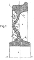
- FIG. 1 is a vertical sectional view of a practical embodiment of the wheel object of the invention.
- the proposed wheel is of the one-piece type (in one piece, plus the accessories) and its shape corresponds to that of a volume of revolution about an axis central ⁇ - ⁇ (except for possible details not obtained by means of the revolution around this axis, such as the oil injection hole or holes, the manufacturing marks, drill holes fixing accessories such as soundproofing rings, discs brake, etc.)
- the parts wheels including the rim (A), the rim-sail (B), the sail or the soul (C), the sail-hub agreement (D) and the hub (E) with the timing hole (F).
- the rim (A) may be of the type shown in the figure or provided with recesses machined on one side or both, for fastening rings soundproofing or any other type of accessories. These rings can be fixed by interference with the machined recess (wedging) or other systems such as holes, orifices, etc. practiced both in the rim and in other areas of the wheel. The presence or absence of a wear limit is optional and does not intervene in the definition proposed wheel concept.
- the passage from the rim (A) to the sail (C) is done by through the Agreement (B), which consists essentially of the use of a approximately circular geometry on both sides, up to the point height (P) where the veil (C) begins. This point (P) is not necessarily located below the center of the rim (theoretical wheel-rail contact point (Z) on the tread), but rather moved to the outer face (1) of the wheel.
- the wheel hub (E) forms a massive volume of revolution around the axis ⁇ - ⁇ , except because of the wedge hole (F) and elements such as the hole or holes oil injection, drill holes threaded or not for fastening elements, etc.
- the hub (E) extends to the agreement (D) with the veil, which consists, again, in a surface having an approximately circular geometry, on both sides of the wheel, up to the point (T), where the veil (C) begins.
- the veil (C) consists of a massive volume of revolution around of the ⁇ - ⁇ axis, except because of the possible presence of drill holes in it, intended for various uses.
- the geometry of the cross-section of the veil (C) is the innovation base that is brought to this invention. This section is covered by a line median theoretical curve, which goes from point (P) to point (T), passing successively by the points (Q), (R) and (S). This line defines the place of points located equidistant both surfaces or faces of the veil, over its entire length.
- the line (P) (S) is constructed thanks to the successive assembly of three curved segments, which are united in two points of inflection (Q) and (S).
- the definition of the points of the outer surfaces of the sail situated at the height "of the points (P), (R) and (T) shall be understood as that of the points situated at the intersection with the external surfaces of the web of lines parallel to the axis ⁇ - ⁇ , each of them passing through the point (Q) or (S) and the center of curvature of the contour of the corresponding surface (points (U), (V), (X) and (Y)).
- the outer surfaces of the first, second and third curvatures of the web have a similar radius of curvature.
- the dimensional relationships between the rays that have been explained so far a preference and an example, without this implying that the subject-matter of the patent not cover non-similar relations between the rays.
- the contour of the surface outer and inner surface of the veil of Figure 1 corresponds to the succession of three circular segments joined gently. This fact is not essentially necessary because it can be three segments in line curved larger orders. It is not either essentially necessary that the values of the radii of curvature of each of the six segments, three for each face, which constitute the outline of the veil be equal between they.
- the wheel is manufactured according to standards and specifications currently existing, published or in the absence of publication (eg prEN 13262).
- the diameter wheel rolling in its initial state is 920 mm.
- the point of wheel-rail contact (Z) being located at 70 mm. the inner face of the rim.
- the birth of sailing takes place at point (P), located at 15 mm. with movement to the outside by report at point (Z).
- the three sections of the outer face of the veil have radii of curvature of, successively, 50, 62.09 and 50 mm.
- the rays of curvature of the three sections of the internal surface of the veil are equal to 70, 42.66 and 70 mm.
- the tuning radii on both sides, external and internal, between the rim and the sail, and also between the sail and the hub, are 50 mm.
- the thickness of the veil decreases gradually, ranging from 28 mm. at the point (T) at 17 mm. at point (P).
- the point (T) is moved 10 mm. outward from the point (Z) contact on the tread.
- the centers of curvature of both sides of the Intermediate section of the veil are located on the same plane, being separated by 4.57 mm.
Landscapes
- Engineering & Computer Science (AREA)
- Mechanical Engineering (AREA)
- Braking Arrangements (AREA)
- Platform Screen Doors And Railroad Systems (AREA)
- Machines For Laying And Maintaining Railways (AREA)
- Testing Of Balance (AREA)
- Lock And Its Accessories (AREA)
Abstract
Description
Lors des années précédentes, le problème, que représente l'action des systèmes de freinage pour la vie en service et les propriétés physiques des roues de chemin de fer, a suscité un intérêt croissant. À l'heure actuelle, il existe plusieurs systèmes de freinage qui s'appliquent aux wagons et aux véhicules ferroviaires. Parmi eux, il faut mentionner les patins de frein agissant directement sur les surfaces de la roue comme, par exemple, la bande de roulement de la jante, les systèmes de freinage par friction sur un disque à cet effet, et les systèmes de freinage électrique avec action directe sur le système de traction, ainsi que des combinaisons de différents systèmes. Chacun d'entre eux a ou peut avoir un effet différent sur la roue ferroviaire mais, en général, la dissipation de la chaleur générée par l'action du système de freinage à travers le volume de la roue est, en principe, un phénomène possible, quel que soit le système, que ce soit par frottement direct des patins sur la roue ou par des phénomènes de blocage ou de patinage de la roue sur le rail. Quoique, pour une moindre part, la présence de phénomènes de glissement de la roue sur le rail se produisant lors des étapes de traction peut également avoir des effets thermiques sur les roues ferroviaires.In previous years, the problem represented by the action of braking systems for life in service and the physical properties of the wheels of railway, has attracted growing interest. At present, there are several braking systems that apply to wagons and railway vehicles. Among they must mention the brake pads acting directly on the surfaces of the wheel as, for example, the tread of the rim, the braking systems by friction on a disc for this purpose, and electrical braking systems with action direct on the traction system, as well as combinations of different systems. Each of them has or may have a different effect on the railway wheel but, in general, the dissipation of heat generated by the action of the braking system through the volume of the wheel is, in principle, a possible phenomenon, whatever the system, whether by direct friction of the pads on the wheel or by blocking phenomena or slippage of the wheel on the rail. Although, to a lesser extent, the presence of sliding phenomena of the wheel on the rail occurring during the traction stages can also have thermal effects on railway wheels.
Parmi tous les effets possibles que peuvent avoir les systèmes de freinage sur les propriétés de la roue, il faut considérer l'apparition de déplacements irréversibles axiaux de toute la jante ou d'une partie par rapport à la géométrie initiale de solide rigide (dans le sens horizontal et perpendiculaire à celui de marche du train), que ce soit pendant le temps où, étant donné de la chaleur dissipée, la roue se trouve à des températures supérieures à la température ambiante, qu'après, également, le refroidissement jusqu'à cette dernière température. Un deuxième effet possible sur la roue est la variation de la valeur des tensions tangentielles qui existent dans le volume de la jante, du fait de cycles thermiques de freinage ou de freinages intenses d'une durée relativement courte. Cette évolution du champ des tensions modifie, bien évidemment, l'état des tensions tangentielles existant au moment de la fabrication de la roue, dont l'optimisation contribue à minimiser le risque de défaillances des roues en service (et, par conséquent, pour la sécurité en marche du train, qu'un fait de cette nature pourrait supposer. Of all the possible effects that braking on the properties of the wheel, it is necessary to consider the appearance of displacements axial irreversible of the entire rim or part of it with respect to the initial geometry of stiff solid (in the horizontal direction and perpendicular to the running direction of the train), that during the time when, given the dissipated heat, the wheel is at temperatures above room temperature, that afterwards also the cooling to this last temperature. A second possible effect on the wheel is the variation in the value of the tangential tensions that exist in the volume of the rim, because of thermal braking cycles or intense braking of a duration relatively short. This evolution of the field of tensions changes, of course, the state of the tangential tensions existing at the time of manufacture of the wheel, optimization helps minimize the risk of wheel failures in service (and, therefore, for the safety of the train, that a fact of this nature could suppose.
On connaít déjà des roues qui essaient de résoudre les problèmes mentionnés et permettent d'obtenir une réduction des déplacements irréversibles de la jante grâce à la modification de la géométrie du voile.We already know wheels that try to solve the problems mentioned and make it possible to obtain a reduction in the irreversible displacements rim thanks to the modification of the geometry of the veil.
Une roue de chemin de fer ayant un voile modifié est connue de EP 0 798 136, où l'on décrit une roue de chemin de fer avec un plan médian perpendiculaire à l'axe XX' de révolution de la roue, et qui présente un voile ayant une première courbure en accord, entre le voile et la jante, se prolongeant par une deuxième courbure en accord entre le voile et le moyeu, la première courbure étant à droite du plan médian et la deuxième à gauche du plan méridien, et de façon symétrique.A railway wheel having a modified sail is known from EP 0 798 136, which describes a railway wheel with a plane median perpendicular to the axis XX 'of revolution of the wheel, and which presents a veil having a first curvature in agreement, between the veil and the rim, extending by a second curvature in agreement between the veil and the hub, the first curvature being right of the median plane and the second to the left of the meridian plane, and symmetrically.
Le demandeur considère que cette géométrie n'arrive pas à surmonter suffisamment les problèmes mentionnés et les exigences des chemins de fer modernes. Applicant considers that this geometry can not overcome enough of the problems mentioned and the requirements of the modern railways.
Le document FR 248 993 A formant l'état de la technique le plus proche selon le préambule de la revendication 1, comprend une roue pleine ayant une faible masse et une haute stabilité de forme dans une direction axiale. La roue pleine présente un voile, un moyeu et une jante, dans laquelle le voile est composé de trois parties courbes selon une fonction cosinusoïdale entre un point où le voile est relié à la jante et le point où le voile est relié au moyeu, dans laquelle le point où le voile est relié à la jante et le point où le voile est relié au moyeu sont disposés dans le plan de contact entre la roue et le rail.The document FR 248 993 A forming the closest state of the art according to the preamble of claim 1, comprises a solid wheel having a low mass and high shape stability in an axial direction. The solid wheel has a sail, a hub and a rim, in which the sail is composed of three curved parts according to a function cosine between a point where the web is connected to the rim and the point where the sail is connected to the hub, in which the point where the sail is connected to the rim and the point where the sail is connected to the hub are arranged in the plane contact between the wheel and the rail.
Le document DE 27 26 871 A décrit une roue de chemin de fer présentant un moyeu prévu sur un axe, une jante et un voile qui est formé d'une partie solidaire en forme de S et monté entre le moyeu et la jante.DE 27 26 871 A describes a railway wheel having a hub provided on an axle, a rim and a sail which is formed of an S-shaped integral portion and mounted between the hub and the rim.
C'est l'objet de la présente invention que de proposer une roue de chemin de fer améliorée qui pallie les problèmes précités et qui satisfasse les exigences des chemins de fer modernes.It is the object of the present invention to propose a wheel of an improved railway that overcomes the above problems and satisfies the requirements of modern railways.
Cet objet est résolu par une roue de chemin de fer selon la revendication 1. This object is solved by a railway wheel according to the claim 1.
Le demandeur considère qu'il est essentiel de doter la roue d'une flexibilité substantiellement supérieure et, pour cela, il développe une roue qui se caractérise par le fait que le voile présente, entre l'accord du voile avec la jante et l'accord du voile avec le moyeu, une première, une deuxième et une troisième courbures s'enchaínant avec un double point d'inflexion, le plan de la face extérieure de la jante étant, de façon approximative, tangentielle à la surface extérieure de la deuxième courbure du voile.The applicant considers it essential to provide the wheel with a substantially greater flexibility and, for that, it develops a wheel which characterized by the fact that the veil presents, between the agreement of the veil with the rim and the agreement of the veil with the hub, a first, a second and a third curvature chaining with a double point of inflection, the plane of the outer face of the rim being, approximately, tangential to the outer surface of the second curvature of the veil.
Avec cette géométrie du voile, les objectifs recherchés de réduction des déformations, de réduction des tensions résiduelles et d'augmentation de la flexibilité visant à absorber les charges d'impact ou vibratoires dans le sens radial, sont atteints.With this geometry of the veil, the desired objectives of reducing deformations, reduction of residual tensions and increased flexibility aimed at absorbing impact or vibratory loads in the radial direction, are achieved.
Le fait que la ligne de charge radiale (charges verticales sur le point (Z) est très proche du point central (T) de l'accord voile-moyeu, permet au moment qu'exerce la charge verticale (permanente dans le train) sur l'accord voile-moyeu d'être très inférieur dans la roue de l'invention à celui de la roue décrite dans l'EP 0798136, en cas d'égalité de charge verticale de la conception. Cette zone d'accord voile-moyeu étant la plus sollicitée en service normal, réduire le moment appliqué sur cette zone (et, par conséquent, l'accroissement des tensions tractives dues à ce moment sur la surface de l'accord) suppose nécessairement un accroissement notable de la résistance à la fatigue mécanique en service de la roue. The fact that the radial load line (vertical loads on the point (Z) is very close to the central point (T) of the sail-hub agreement, allows the moment exercised by the vertical load (permanent in the train) on the sail-hub agreement of being much lower in the wheel of the invention than that of the wheel described in EP 0798136, in case of vertical load equalization of the design. This veil-hub agreement area being the most requested in normal service, reduce the time applied to this area (and, by Consequently, the increase in tractive stresses due to this moment on the surface of the agreement) necessarily implies a significant increase in fatigue resistance mechanical in service of the wheel.
Le fait que le point le plus saillant de la face externe du voile coïncide pratiquement avec le plan de la face externe de la jante assure le maximum de flexibilité axiale et radiale au voile, car, si ce point dépassait clairement de ce plan, il pourrait y avoir des problèmes de montage ou des interférences avec d'autres éléments mécaniques.The fact that the most salient point of the outer face of the veil coincides practically with the plane of the outer side of the rim ensures maximum flexibility axial and radial to the veil, because, if this point clearly exceeded this plane, it could have mounting problems or interference with other elements mechanical.
Comme effet secondaire, on obtient une roue dont la masse est plus réduite que celle des roues connues à l'heure actuelle, pour une même charge maximale par essieu ferroviaire.As a side effect, we get a wheel whose mass is more reduced than that of the wheels known at present, for the same maximum load by rail axle.
La position des deux points d'accord (P), (T) seront, de préférence, du même côté extérieur du plan médian théorique (Z), afin de faciliter la flexibilité et de compenser des flexions des masses jante-moyeu, quoique d'autres positionnements soient admis.The position of the two points of agreement (P), (T) will preferably be same side of the theoretical median plane (Z), in order to facilitate flexibility and to compensate for bending of the rim-hub masses, although other positioning be admitted.
L'apparition de déplacements irréversibles, à chaud ou à froid, de la jante ou de parties de celle-ci dans le sens latéral ou axial, quel qu'en soit le sens, suppose nécessairement une variation de la distance existant entre les faces de la jante et les surfaces latérales du moyeu de la roue et, donc, de la distance entre les faces internes des jantes des roues qui constituent un essieu ferroviaire. Une augmentation de cette distance entre les faces des jantes de roues provoque un frottement excessif des boudins sur les rails et leur usure prématurée. Une diminution de cette distance, pour sa part, accroít le risque de problèmes et même le déraillement au passage du train au niveau d'aiguillages, d'appareils de voie ou de zones de plus grande distance entre les rails. Une manière d'éviter ce problème est la limitation traditionnelle de la charge par essieu et de la vitesse de service, notamment sur les lignes en forte pente, afin de diminuer la dissipation de la chaleur générée par l'action des freins en service normal et lors des arrêts d'urgence. Une autre alternative consiste dans l'introduction d'une géométrie appropriée du voile, qui diminue la tendance à l'apparition de déformations du voile, à chaud ou à froid, ce qui se traduit ultérieurement en déplacements irréversibles de la jante, comme c'est le cas pour le nouveau concept de roue proposé qui, en même temps, présente, comme avantage additionnel, la diminution du poids total de la roue par rapport à d'autres concepts antérieurs. The occurrence of irreversible displacements, hot or cold, of the rim or parts thereof in the lateral or axial direction, whatever their meaning, necessarily assumes a variation in the distance between the rim faces and the side surfaces of the wheel hub and, therefore, the distance between the inner faces wheel rims that constitute a railway axle. An increase of this distance between the faces of the wheel rims causes excessive friction of the strands on the rails and their premature wear. A decrease in this distance, for its part, increase the risk of problems and even the train derailment switches, turnouts or areas of greater distance between the rails. A way of avoiding this problem is the traditional limitation of axle load and the speed of service, particularly on steeply sloping lines, in order to reduce the dissipation of the heat generated by the action of the brakes in normal service and during emergency stops. Another alternative is to introduce geometry veil, which decreases the tendency for the appearance of deformations of the veil, to hot or cold, which subsequently results in irreversible movements of the rim, as is the case for the proposed new wheel concept which, at the same time, presents, as an additional advantage, the reduction of the total weight of the wheel by compared to other previous concepts.
À part le problème des déplacements irréversibles de jante, décrits aux paragraphes précédents, un deuxième objectif de notre concept de roue présenté ici, est la contention des valeurs des tensions tangentielles dans la jante à un niveau de saturation acceptable. En effet, les roues ferroviaires monobloc sont fabriquées au moyen d'une série de processus tendant à la production de tensions tangentielles négatives dans le volume de la jante, qui génèrent un état compressif de celle-ci, qui tend à la fermer en réduisant son diamètre. Toutefois, des applications intenses ou répétitives des systèmes ou des cycles de freinage sont la cause de la production de chaleur qui, à la suite de l'élévation intense de la température des couches extérieures de la jante de la roue, peut donner lieu, en certaines occasions, à l'apparition de phénomènes de transformation structurale de l'acier qui compose les jantes, et il arrive même, dans les cas les plus extrêmes, qu'apparaissent ded crevasses sur la surface de roulement. En tout cas, et même s'il n'y a pas de transformations intenses, les cycles thermiques conduisent, dans le temps, à une évolution des tensions tangentielles vers des valeurs plus élevées, voire positives, qui tendent, à présent, à ouvrir la jante. Ainsi, de petites crevasses de roulement peuvent avoir un accroissement favorisé par un mécanisme de fatigue pouvant aller jusqu'à provoquer des ruptures ou des pannes importantes dans les roues des véhicules ferroviaires, voire mettre en péril la sécurité de marche du train. Comme il a été auparavant, la contention à des niveaux acceptables de la valeur des tensions tangentielles en service est un second objectif du nouveau modèle de roue proposé. Aussi bien cet objectif que celui de la minimisation du déplacement irréversible de la jante est atteint grâce à une forme de voile de roue innovatrice.Apart from the problem of irreversible rim displacements, described in previous paragraphs, a second objective of our wheel concept presented here, is contention tangential tension values in the rim at a level of acceptable saturation. In fact, monobloc railway wheels are manufactured using of a series of processes tending to the production of negative tangential tensions in the volume of the rim, which generate a compressive state of it, which tends to close it in reducing its diameter. However, intense or repetitive applications of the systems or braking cycles are the cause of heat production which, as a result of the intense rise in the temperature of the outer layers of the rim of the wheel, can give rise, on certain occasions, to the appearance of transformation phenomena structural steel that makes up the rims, and it even happens, in the most cases extreme, that appear cracks on the running surface. In any case, and even if there are no intense transformations, the thermal cycles lead, in time, to a change in tangential tensions towards higher values, even positive, which tend, now, to open the rim. Thus, small crevasses of may have an increase favored by a fatigue mechanism go as far as to cause breakages or major breakdowns in the wheels of railway vehicles or even jeopardize the running safety of the train. As he has previously been the contention at acceptable levels of the value of the tensions tangential in service is a second objective of the proposed new wheel model. This objective as well as that of minimizing the irreversible displacement of rim is achieved through an innovative form of wheel sail.
Pour mieux comprendre l'objet de la pre'sente invention, on a représenté sur les plans une forme préférentielle de réalisation pratique, susceptible de changements accessoires qui n'en dénaturent pas le fondement.To better understand the object of the present invention, we have represented in the plans a preferred form of practical realization, capable of incidental changes that do not distort the foundation.
La figure 1 est une vue en coupe verticale d'une réalisation pratique de la roue objet de l'invention.FIG. 1 is a vertical sectional view of a practical embodiment of the wheel object of the invention.
On décrit ci-dessous un exemple de réalisation pratique, non limitative, de la présente invention. An exemplary practical, nonlimiting embodiment is described below, of the present invention.
La roue proposée est du type monobloc (d'une seule pièce, plus les accessoires) et sa forme correspond à celle d'un volume de révolution autour d'un axe central α-α (sauf pour des détails possibles non obtenus au moyennant la révolution autour de cet axe, tels que le ou les trous d'injection d'huile, les marques de fabrication, les trous de foret de fixation d'accessoires tels que bagues d'insonorisation, disques de frein, etc.) Dans la section en coupe montrée à la figure 1, on peut observer les parties essentielles de la roue, notamment la jante (A), l'accord jante-voile (B), le voile ou âme (C), l'accord voile-moyeu (D) et le moyeu (E) avec le trou de calage (F).The proposed wheel is of the one-piece type (in one piece, plus the accessories) and its shape corresponds to that of a volume of revolution about an axis central α-α (except for possible details not obtained by means of the revolution around this axis, such as the oil injection hole or holes, the manufacturing marks, drill holes fixing accessories such as soundproofing rings, discs brake, etc.) In the section section shown in Figure 1, the parts wheels, including the rim (A), the rim-sail (B), the sail or the soul (C), the sail-hub agreement (D) and the hub (E) with the timing hole (F).
La jante (A) peut être du type montré sur la figure ou munis de renfoncements usinés sur un côté ou sur les deux, pour la fixation de bagues d'insonorisation ou tout autre type d'accessoires. Ces bagues peuvent être fixées par interférence avec le renfoncement usiné (calage) ou au moyen d'autres systèmes tels que trous, orifices, etc. pratiqués aussi bien dans la jante que dans d'autres zones de la roue. La présence ou non de limite d'usure est optionnelle et n'intervient pas dans la définition de concept de roue proposé. Le passage de la jante (A) au voile (C) se fait par l'intermédiaire de l'accord (B), qui consiste essentiellement dans l'utilisation d'une géométrie approximativement circulaire sur les deux faces, jusqu'à la hauteur du point (P) où commence le voile (C). Ce point (P) n'est pas nécessairement situé au-dessous du centre de la jante (point de contact théorique roue-rail (Z) sur la bande de roulement), mais plutôt déplacé vers la face extérieure (1) de la roue.The rim (A) may be of the type shown in the figure or provided with recesses machined on one side or both, for fastening rings soundproofing or any other type of accessories. These rings can be fixed by interference with the machined recess (wedging) or other systems such as holes, orifices, etc. practiced both in the rim and in other areas of the wheel. The presence or absence of a wear limit is optional and does not intervene in the definition proposed wheel concept. The passage from the rim (A) to the sail (C) is done by through the Agreement (B), which consists essentially of the use of a approximately circular geometry on both sides, up to the point height (P) where the veil (C) begins. This point (P) is not necessarily located below the center of the rim (theoretical wheel-rail contact point (Z) on the tread), but rather moved to the outer face (1) of the wheel.
Le fait que le point (P) soit déplacé vers la face intérieure de la roue entre dans l'objet du Brevet.The fact that the point (P) is moved towards the inside of the wheel enters the subject of the patent.
Le moyeu de roue (E) forme un volume de révolution massif autour de l'axe α-α, sauf du fait du trou de calage (F) et des éléments tels que le ou les trous d'injection d'huile, les trous de foret filetés ou non pour la fixation d'éléments, etc. Le moyeu (E) s'étend jusqu'à l'accord (D) avec le voile, qui consiste, de nouveau, en une surface ayant une géométrie approximativement circulaire, sur les deux côtés de la roue, jusqu'à hauteur du point (T), où commence le voile (C).The wheel hub (E) forms a massive volume of revolution around the axis α-α, except because of the wedge hole (F) and elements such as the hole or holes oil injection, drill holes threaded or not for fastening elements, etc. The hub (E) extends to the agreement (D) with the veil, which consists, again, in a surface having an approximately circular geometry, on both sides of the wheel, up to the point (T), where the veil (C) begins.
Enfin, le voile (C) consiste en un volume massif de révolution autour de l'axe α-α, sauf du fait de la présence possible de trous de foret dans celui-ci, destinés à divers usages. La géométrie de la section en coupe du voile (C) constitue l'innovation de base qui est apportée à cette invention. Cette section est parcourue par une ligne médiane théorique courbe, qui va du point (P) au point (T), en passant successivement par les points (Q), (R) et (S). Cette ligne définit le lieu de points situés à égale distance des deux surfaces ou faces du voile, sur toute sa longueur. La ligne (P) (S) est construite grâce à l'assemblage successif de trois segments courbes, qui sont unis en deux points d'inflexion (Q) et (S).Finally, the veil (C) consists of a massive volume of revolution around of the α-α axis, except because of the possible presence of drill holes in it, intended for various uses. The geometry of the cross-section of the veil (C) is the innovation base that is brought to this invention. This section is covered by a line median theoretical curve, which goes from point (P) to point (T), passing successively by the points (Q), (R) and (S). This line defines the place of points located equidistant both surfaces or faces of the veil, over its entire length. The line (P) (S) is constructed thanks to the successive assembly of three curved segments, which are united in two points of inflection (Q) and (S).
La définition des points des surfaces extérieures du voile situés "à la hauteur" des points (P), (R) et (T) doit être comprise comme celle des points situés à l'intersection avec les surfaces externes du voile des lignes parallèles à l'axe α-α, chacune d'entre elles passant par le point (Q) ou (S) et le centre de courbure du contour de la surface correspondante (les points (U), (V), (X) et (Y)). Ces définitions s'appliquent aux paragraphes précédents et aux suivants.The definition of the points of the outer surfaces of the sail situated at the height "of the points (P), (R) and (T) shall be understood as that of the points situated at the intersection with the external surfaces of the web of lines parallel to the axis α-α, each of them passing through the point (Q) or (S) and the center of curvature of the contour of the corresponding surface (points (U), (V), (X) and (Y)). These definitions apply to the preceding and following paragraphs.
Certains rapports entre les différents rayons d'accord sont préférables, dans le but d'obtenir le maximum d'élasticité axiale et radiale du voile, et avec elles, les objectifs finals définis aux paragraphes précédents. De cette façon, le rayon d'accord (R2) de la face externe du voile entre les hauteurs des points (P) et (Q) est similaire au rayon (R0) de l'accord jante-voile (B) sur cette face. Ce rayon (R0) est également similaire au rayon (R6) de la face externe du voile entre les hauteurs des points (S) et (T), à son tour semblable au rayon (R4) de courbure de l'accord voile-moyeu (D) sur cette face extérieure. Ces rayons (R0), (R2), (R6), (R4) peuvent être, en outre, égaux aux rayons (R1), (R3), des accords jante-voile (B) et voile-moyeu (B) sur la face interne de la roue. Enfin, le rayon (R7) d'accord de la face interne entre la hauteur des points (P) et (Q) et le rayon (R8) d'accord de la même face interne entre la hauteur des points (S) et (T), peuvent également être égaux entre eux. Finalement, les rayons (R9), (R5) d'accord des faces interne et externe du voile entre les hauteurs des points (Q) et (S) sont nécessairement différents entre eux. Dans la nouvelle roue qui est proposée, c'est précisément la combinaison appropriée des rayons de courbure des faces internes et externes de chacun des trois tronçons de voile compris entre les points (P) et (T), la position des centres respectifs de courbure et la position de l'ensemble du voile par rapport à la jante et au moyeu, qui permet l'obtention des objectifs proposés. Notamment, grâce à l'utilisation d'une combinaison telle qu'elle permette:
- La triple courbure maximale du voile entre les points (P) et (T), de telle sorte que la face externe du voile, à la hauteur du point (R) coïncide approximativement avec la face externe de la jante, pouvant faire saillie sur celle-ci ou demeurer dans une position légèrement plus intérieure, en fonction des besoins de la conception particulière ou des tolérances de fabrication.
- L'obtention de transitions douces entre les différents tronçons des surfaces externes du voile et de celles-ci avec les accords jante-voile et moyeu-voile.
- The maximum triple curvature of the web between the points (P) and (T), so that the outer face of the web, at the height of the point (R) coincides approximately with the outer face of the rim, which can project on that or remain in a slightly more interior position, depending on the needs of the particular design or manufacturing tolerances.
- Obtaining smooth transitions between the different sections of the outer surfaces of the sail and of these with the rims-sail and hub-sail.
De préférence, et de façon approximative, les surfaces extérieures des première, deuxième et troisième courbures du voile ont un rayon de courbure similaire. En général, les rapports dimensionnels entre les rayons qui ont été expliqués jusqu'ici sont une préférence et un exemple, sans que cela suppose que l'objet du Brevet ne couvre pas des rapports non-similaires entre les rayons.Preferably, and approximately, the outer surfaces of the first, second and third curvatures of the web have a similar radius of curvature. In general, the dimensional relationships between the rays that have been explained so far a preference and an example, without this implying that the subject-matter of the patent not cover non-similar relations between the rays.
On peut dire que, de façon préférentielle, le contour de la surface externe et de la surface interne du voile de la figure 1 correspond à la succession de trois segments circulaires joints doucement. Ce fait n'est pas essentiellement nécessaire, car il peut s'agir de trois segments en ligne courbe de plus grands ordres. Il n'est pas non plus essentiellement nécessaire que les valeurs des rayons de courbure de chacun des six segments, trois pour chaque face, qui constituent le contour du voile soit égales entre elles.It can be said that, preferably, the contour of the surface outer and inner surface of the veil of Figure 1 corresponds to the succession of three circular segments joined gently. This fact is not essentially necessary because it can be three segments in line curved larger orders. It is not either essentially necessary that the values of the radii of curvature of each of the six segments, three for each face, which constitute the outline of the veil be equal between they.
La roue est fabriquée conformément aux normes et aux spécifications actuellement existantes, publiées ou à défaut de publication (par ex., prEN 13262).The wheel is manufactured according to standards and specifications currently existing, published or in the absence of publication (eg prEN 13262).
Enfin, il faut mentionner que la présence de déviations dimensionnelles dues à des processus de fabrication peuvent faire varier, de manière plus ou moins significative, les dimensions réelles de la roue par rapport aux critères dimensionnels définis dans les paragraphes précédents.Finally, it must be mentioned that the presence of deviations dimensions due to manufacturing processes can vary, more or less significant, the actual dimensions of the wheel against the criteria dimensions defined in the previous paragraphs.
À titre d'application particulière du concept de roue exposé précédemment, on a développé une roue avec un système de freinage par patin sur la bande de roulement, où la charge maximale par essieu est établi, en principe, à 22.5 tonnes (bien qu'il soit possible d'appliquer des charges plus grandes), et dans des conditions de freinage telles qu'elles ont été définies pour cette charge, dans le projet de norme UIC 510-5.As a special application of the wheel concept previously, a wheel with a pad brake system was developed on the tread, where the maximum axle load is established, in principle, at 22.5 tonnes (although it is possible to apply larger loads), and in braking conditions as defined for this load, in the draft UIC standard 510-5.
Il s'agit d'une roue fabriquée en acier au carbone au moyen du forgeage et du laminage, avec des surfaces externes complètement usinées. Le diamètre de roulement de la roue dans son état initial (fabrication) est de 920 mm., le point de contact roue-rail (Z) étant situé à 70 mm. de la face interne de la jante. La naissance du voile a lieu au point (P), situé à 15 mm. avec déplacement vers la face extérieure par rapport au point (Z). Les trois tronçons de la face extérieure du voile présentent des rayons de courbure de, successivement, 50, 62.09 et 50 mm. En même temps, les rayons de courbure des trois tronçons de la surface interne du voile sont égaux à 70, 42.66 et 70 mm. Enfin, les rayons d'accord sur les deux faces, externe et interne, entre la jante et le voile, et également entre le voile et le moyeu, sont de 50 mm. L'épaisseur du voile decroít peu à peu, allant de 28 mm. au point (T) à 17 mm. au point (P).It is a wheel made of carbon steel using the forging and rolling, with fully machined external surfaces. The diameter wheel rolling in its initial state (manufacture) is 920 mm., the point of wheel-rail contact (Z) being located at 70 mm. the inner face of the rim. The birth of sailing takes place at point (P), located at 15 mm. with movement to the outside by report at point (Z). The three sections of the outer face of the veil have radii of curvature of, successively, 50, 62.09 and 50 mm. At the same time, the rays of curvature of the three sections of the internal surface of the veil are equal to 70, 42.66 and 70 mm. Finally, the tuning radii on both sides, external and internal, between the rim and the sail, and also between the sail and the hub, are 50 mm. The thickness of the veil decreases gradually, ranging from 28 mm. at the point (T) at 17 mm. at point (P).
Le point (T) est déplacé de 10 mm. vers l'extérieur par rapport au point (Z) de contact sur la bande de roulement. Les centres de courbure des deux faces du tronçon intermédiaire du voile sont situés sur le même plan, étant séparés de 4.57 mm. La face externe du tronçon intermédiaire, pour sa part, coïncide en son point le plus saillant avec le niveau de la face externe de la jante.The point (T) is moved 10 mm. outward from the point (Z) contact on the tread. The centers of curvature of both sides of the Intermediate section of the veil are located on the same plane, being separated by 4.57 mm. The outer face of the intermediate section, for its part, coincides at its most protruding with the level of the outer face of the rim.
Les résultats obtenus avec cette roue ont été clairement supérieurs à ceux obtenus avec une roue à double courbure.The results obtained with this wheel were clearly superior to those obtained with a double-curvature wheel.
Claims (6)
- Railway wheel forming a rotation solid about an axis a-a, which is comprised of a rim (A), a hub (B) and a wheel centre (C) having, on the rim, a theoretical median plane (Z) which passes through the point of contact between the wheel and the rail and which is perpendicular to this axis a-a, the wheel centre (C) being united with the rim (A) by an inner connecting surface and an outer connecting surface, and the wheel centre (C) being united to the hub (E) by an inner connecting surface and an outer connecting surface allowing to determine, on the wheel centre (C), a theoretical median line which extends from the connection (P) of the wheel centre (C) with the rim (A) to the connection (T) of the wheel centre (C) with the hub (E), the wheel centre having, between the connection of the wheel centre (C) with the rim (A) and the connection of the wheel centre (C) with the hub (E), a first, a second and a third curvature which are concatenated with a double point of inflection,
characterized in that
the plane of the outer face (1) of the rim (A) is approximately tangential to the outer surface of the second curvature of the wheel centre (C), and
the connection (P) of the wheel centre (C) with the rim (A) and the connection (T) of the wheel centre (C) with the hub (E) are offset with regard to the theoretical median plane (Z) of contact between the wheel and the rail. - Railway wheel according to the preceding claim, characterised in that the connection (P) of the wheel centre (C) with the rim (A) and the connection (T) of the wheel centre (C) with the hub (E) are on the same outer side of the theoretical median plane (Z) of contact between the wheel and the rail.
- Railway wheel according to claim 1, characterised in that, in an approximate way, the outer surfaces of the first, second and third curvatures of the wheel centre have a similar radius of curvature.
- Railway wheel according to claim 1, characterised in that, in an approximate way, the inner surfaces of the first, second and third curvatures of the wheel centre have a similar radius of curvature.
- Railway wheel according to claim 1, characterised in that the outer surface of the first curvature is an extension having the same concavity, centre and radius as the outer connecting surface between the rim and the wheel centre, and in that the outer surface of the third curvature is an extension having the same concavity, centre and radius as the outer connecting surface between the wheel centre and the hub.
- Railway wheel according to claim 1, characterised in that the connection (T) of the wheel centre (C) with the hub (E) is close to the median plane (Z).
Priority Applications (5)
| Application Number | Priority Date | Filing Date | Title |
|---|---|---|---|
| DK01500018T DK1225065T3 (en) | 2001-01-17 | 2001-01-17 | rail Wheel |
| DE60115832T DE60115832T2 (en) | 2001-01-17 | 2001-01-17 | railway wheel |
| EP01500018A EP1225065B1 (en) | 2001-01-17 | 2001-01-17 | Railway wheel |
| ES01500018T ES2251452T3 (en) | 2001-01-17 | 2001-01-17 | RAILWAY WHEEL. |
| AT01500018T ATE312725T1 (en) | 2001-01-17 | 2001-01-17 | RAILWAY WHEEL |
Applications Claiming Priority (1)
| Application Number | Priority Date | Filing Date | Title |
|---|---|---|---|
| EP01500018A EP1225065B1 (en) | 2001-01-17 | 2001-01-17 | Railway wheel |
Publications (2)
| Publication Number | Publication Date |
|---|---|
| EP1225065A1 EP1225065A1 (en) | 2002-07-24 |
| EP1225065B1 true EP1225065B1 (en) | 2005-12-14 |
Family
ID=8183458
Family Applications (1)
| Application Number | Title | Priority Date | Filing Date |
|---|---|---|---|
| EP01500018A Expired - Lifetime EP1225065B1 (en) | 2001-01-17 | 2001-01-17 | Railway wheel |
Country Status (5)
| Country | Link |
|---|---|
| EP (1) | EP1225065B1 (en) |
| AT (1) | ATE312725T1 (en) |
| DE (1) | DE60115832T2 (en) |
| DK (1) | DK1225065T3 (en) |
| ES (1) | ES2251452T3 (en) |
Families Citing this family (9)
| Publication number | Priority date | Publication date | Assignee | Title |
|---|---|---|---|---|
| CZ293896B6 (en) | 2003-01-15 | 2004-08-18 | Bonatransáa@S | Stable railway wheel |
| ITBS20060172A1 (en) | 2006-08-04 | 2008-02-05 | Lucchini Sidermeccanica Spa | WHEEL FOR RAILWAY VEHICLES WITH HIGH BRACING CAPACITY |
| UA78956C2 (en) * | 2006-09-13 | 2007-04-25 | Interpipe Nyzhniodniprovsk Tub | Solid-rolled railroad wheel |
| UA78957C2 (en) | 2006-09-13 | 2007-04-25 | Interpipe Nyzhniodniprovsk Tub | Solid-rolled railroad wheel |
| RU2486063C1 (en) * | 2011-12-16 | 2013-06-27 | Открытое Акционерное Общество "Выксунский Металлургический Завод" | Railway wheel |
| WO2013103327A1 (en) * | 2012-01-03 | 2013-07-11 | Публичное Акционерное Общество "Интерпайп Ижнеднепровский Трубопрокатный Завод" | Solid-rolled railway wheel |
| RU2682748C1 (en) * | 2017-10-04 | 2019-03-21 | Закрытое акционерное общество "УралСофт" | Method and device for automatic quality control of surface strengthening of solid-rolled wheels parts with shot flow |
| RU2715826C1 (en) * | 2019-07-29 | 2020-03-03 | Общество С Ограниченной Ответственностью "Научно-Исследовательский Институт Транспортного Машиностроения" | Railway wheel |
| DE202023106870U1 (en) | 2023-01-25 | 2024-01-12 | Bonatrans Group A.S. | Railway wheel |
Family Cites Families (5)
| Publication number | Priority date | Publication date | Assignee | Title |
|---|---|---|---|---|
| CH258209A (en) * | 1944-12-11 | 1948-11-15 | Aktiebolag Degerfors Jarnverks | Disc wheel for rail and tram cars. |
| DE2726871A1 (en) * | 1977-06-15 | 1979-01-04 | Schwaebische Huettenwerke Gmbh | High speed train wheel - has tyre mounted on corrugated disc with deformed S=section including thickened region towards hub |
| DD159501A3 (en) | 1980-07-03 | 1983-03-16 | Olaf Reich | FULL WHEEL FOR RAIL VEHICLES |
| BR8907422A (en) * | 1989-02-17 | 1991-05-07 | Dn Metall Inst | WHEEL FOR RAILWAYS |
| FR2746707B1 (en) | 1996-03-29 | 1998-04-24 | Valdunes | RAILWAY WHEEL |
-
2001
- 2001-01-17 AT AT01500018T patent/ATE312725T1/en active
- 2001-01-17 EP EP01500018A patent/EP1225065B1/en not_active Expired - Lifetime
- 2001-01-17 DK DK01500018T patent/DK1225065T3/en active
- 2001-01-17 ES ES01500018T patent/ES2251452T3/en not_active Expired - Lifetime
- 2001-01-17 DE DE60115832T patent/DE60115832T2/en not_active Expired - Lifetime
Also Published As
| Publication number | Publication date |
|---|---|
| EP1225065A1 (en) | 2002-07-24 |
| ATE312725T1 (en) | 2005-12-15 |
| DE60115832D1 (en) | 2006-01-19 |
| DE60115832T2 (en) | 2006-07-27 |
| ES2251452T3 (en) | 2006-05-01 |
| DK1225065T3 (en) | 2006-04-03 |
Similar Documents
| Publication | Publication Date | Title |
|---|---|---|
| EP1225065B1 (en) | Railway wheel | |
| CA2341609C (en) | Threaded connection of two metal tubes with high tightening torque | |
| KR102528140B1 (en) | Vehicle wheel disk, vehicle wheel including wheel disk and method for manufacturing wheel disk and vehicle wheel | |
| AU663992B2 (en) | Railway wheel and method of manufacture | |
| EP0912352B1 (en) | Sound absorbing wheel | |
| US10661603B2 (en) | Solid wheel for a rail vehicle and method for producing the wheel | |
| FR2515442A1 (en) | IMPROVEMENTS ON ROTORS OF ELECTROMAGNETIC RETARDERS | |
| EP1382877B1 (en) | Aircraft multi-disc brake system | |
| US7188711B2 (en) | Disc to central part interface for disc brakes | |
| FR2762653A1 (en) | BRAKE DISC HAVING A FRICTION PART OF COMPOSITE MATERIAL LINKED TO A METAL PART | |
| EP0633149B1 (en) | Determination procedure of the track of the axial section of a wheel and such a wheel | |
| FR2567457A1 (en) | SAFETY RIM COMPRISING A BUMPER OF AXIAL RETENTION OF THE BALL OF HIGH HEIGHT, AND PNEUMATIC ASSEMBLY USING SUCH A RIM | |
| FR2830914A1 (en) | Brake drum has braking track carried by wheel hub and heat dissipater | |
| JP3818212B2 (en) | Fastening structure of railcar brake disc and railcar wheel and wheel axle | |
| EP3932690B1 (en) | Railway wheel with low deformation | |
| FR2878593A1 (en) | Monoblock disc brake disc for motor vehicle, has two blades connecting inner and outer frictional tracks together and forming junction units to connect tracks to circular tulip, where blades are separated from each other by gap | |
| RU2408470C2 (en) | All-rolled railroad wheel | |
| FR2989137A1 (en) | METHOD OF USING AND RENOVATING A DISC OF A DISC STACK OF A BRAKE OF A VEHICLE | |
| EP0638444B1 (en) | Integral type wheel for railway material e.g. motorvehicle or wagon | |
| FR3065045B3 (en) | BRAKE DISC FULL FOR VEHICLES | |
| RU91936U1 (en) | ONE-WHEELED WHEEL OF HIGH-SPEED RAILWAY VEHICLE | |
| BE361026A (en) | ||
| RU2408468C2 (en) | All-rolled railroad wheel | |
| JP2002048167A (en) | Brake disc | |
| BE491975A (en) |
Legal Events
| Date | Code | Title | Description |
|---|---|---|---|
| PUAI | Public reference made under article 153(3) epc to a published international application that has entered the european phase |
Free format text: ORIGINAL CODE: 0009012 |
|
| AK | Designated contracting states |
Kind code of ref document: A1 Designated state(s): AT BE CH CY DE DK ES FI FR GB GR IE IT LI LU MC NL PT SE TR |
|
| AX | Request for extension of the european patent |
Free format text: AL;LT;LV;MK;RO;SI |
|
| 17P | Request for examination filed |
Effective date: 20030124 |
|
| AKX | Designation fees paid |
Designated state(s): AT BE CH CY DE DK ES FI FR GB GR IE IT LI LU MC NL PT SE TR |
|
| TPAD | Observations filed by third parties |
Free format text: ORIGINAL CODE: EPIDOS TIPA |
|
| 17Q | First examination report despatched |
Effective date: 20040816 |
|
| GRAP | Despatch of communication of intention to grant a patent |
Free format text: ORIGINAL CODE: EPIDOSNIGR1 |
|
| GRAS | Grant fee paid |
Free format text: ORIGINAL CODE: EPIDOSNIGR3 |
|
| GRAA | (expected) grant |
Free format text: ORIGINAL CODE: 0009210 |
|
| AK | Designated contracting states |
Kind code of ref document: B1 Designated state(s): AT BE CH CY DE DK ES FI FR GB GR IE IT LI LU MC NL PT SE TR |
|
| REG | Reference to a national code |
Ref country code: GB Ref legal event code: FG4D Free format text: NOT ENGLISH |
|
| RIN1 | Information on inventor provided before grant (corrected) |
Inventor name: FERNAENDEZ LOPETEGUI, FELIX Inventor name: CASTA?ARES ETXEZARRETA, AITOR Inventor name: GALARZA RODR GUEZ, AITOR |
|
| REG | Reference to a national code |
Ref country code: CH Ref legal event code: EP |
|
| REG | Reference to a national code |
Ref country code: IE Ref legal event code: FG4D Free format text: LANGUAGE OF EP DOCUMENT: FRENCH |
|
| REF | Corresponds to: |
Ref document number: 60115832 Country of ref document: DE Date of ref document: 20060119 Kind code of ref document: P |
|
| PG25 | Lapsed in a contracting state [announced via postgrant information from national office to epo] |
Ref country code: MC Free format text: LAPSE BECAUSE OF NON-PAYMENT OF DUE FEES Effective date: 20060131 |
|
| REG | Reference to a national code |
Ref country code: CH Ref legal event code: NV Representative=s name: ING. MARCO ZARDI C/O M. ZARDI & CO. S.A. |
|
| GBT | Gb: translation of ep patent filed (gb section 77(6)(a)/1977) |
Effective date: 20060107 |
|
| REG | Reference to a national code |
Ref country code: SE Ref legal event code: TRGR |
|
| REG | Reference to a national code |
Ref country code: DK Ref legal event code: T3 |
|
| REG | Reference to a national code |
Ref country code: ES Ref legal event code: FG2A Ref document number: 2251452 Country of ref document: ES Kind code of ref document: T3 |
|
| REG | Reference to a national code |
Ref country code: GR Ref legal event code: EP Ref document number: 20060400963 Country of ref document: GR |
|
| PLBE | No opposition filed within time limit |
Free format text: ORIGINAL CODE: 0009261 |
|
| STAA | Information on the status of an ep patent application or granted ep patent |
Free format text: STATUS: NO OPPOSITION FILED WITHIN TIME LIMIT |
|
| 26N | No opposition filed |
Effective date: 20060915 |
|
| PGFP | Annual fee paid to national office [announced via postgrant information from national office to epo] |
Ref country code: NL Payment date: 20071228 Year of fee payment: 8 |
|
| PG25 | Lapsed in a contracting state [announced via postgrant information from national office to epo] |
Ref country code: CY Free format text: LAPSE BECAUSE OF FAILURE TO SUBMIT A TRANSLATION OF THE DESCRIPTION OR TO PAY THE FEE WITHIN THE PRESCRIBED TIME-LIMIT Effective date: 20051214 |
|
| PGFP | Annual fee paid to national office [announced via postgrant information from national office to epo] |
Ref country code: GR Payment date: 20080110 Year of fee payment: 8 |
|
| NLV4 | Nl: lapsed or anulled due to non-payment of the annual fee |
Effective date: 20090801 |
|
| PG25 | Lapsed in a contracting state [announced via postgrant information from national office to epo] |
Ref country code: NL Free format text: LAPSE BECAUSE OF NON-PAYMENT OF DUE FEES Effective date: 20090801 |
|
| PG25 | Lapsed in a contracting state [announced via postgrant information from national office to epo] |
Ref country code: GR Free format text: LAPSE BECAUSE OF NON-PAYMENT OF DUE FEES Effective date: 20090804 |
|
| REG | Reference to a national code |
Ref country code: FR Ref legal event code: PLFP Year of fee payment: 16 |
|
| REG | Reference to a national code |
Ref country code: FR Ref legal event code: PLFP Year of fee payment: 17 |
|
| REG | Reference to a national code |
Ref country code: FR Ref legal event code: PLFP Year of fee payment: 18 |
|
| PGFP | Annual fee paid to national office [announced via postgrant information from national office to epo] |
Ref country code: LU Payment date: 20190128 Year of fee payment: 19 |
|
| PGFP | Annual fee paid to national office [announced via postgrant information from national office to epo] |
Ref country code: CH Payment date: 20190204 Year of fee payment: 19 Ref country code: DE Payment date: 20190129 Year of fee payment: 19 Ref country code: IE Payment date: 20190128 Year of fee payment: 19 Ref country code: GB Payment date: 20190128 Year of fee payment: 19 Ref country code: ES Payment date: 20190201 Year of fee payment: 19 Ref country code: IT Payment date: 20190123 Year of fee payment: 19 Ref country code: FI Payment date: 20190129 Year of fee payment: 19 Ref country code: FR Payment date: 20190125 Year of fee payment: 19 |
|
| PGFP | Annual fee paid to national office [announced via postgrant information from national office to epo] |
Ref country code: AT Payment date: 20190103 Year of fee payment: 19 Ref country code: DK Payment date: 20190129 Year of fee payment: 19 Ref country code: TR Payment date: 20190111 Year of fee payment: 19 Ref country code: BE Payment date: 20190128 Year of fee payment: 19 Ref country code: SE Payment date: 20190129 Year of fee payment: 19 |
|
| PGFP | Annual fee paid to national office [announced via postgrant information from national office to epo] |
Ref country code: PT Payment date: 20190104 Year of fee payment: 19 |
|
| REG | Reference to a national code |
Ref country code: DE Ref legal event code: R119 Ref document number: 60115832 Country of ref document: DE |
|
| REG | Reference to a national code |
Ref country code: FI Ref legal event code: MAE |
|
| REG | Reference to a national code |
Ref country code: DK Ref legal event code: EBP Effective date: 20200131 Ref country code: CH Ref legal event code: PL |
|
| REG | Reference to a national code |
Ref country code: SE Ref legal event code: EUG |
|
| REG | Reference to a national code |
Ref country code: AT Ref legal event code: MM01 Ref document number: 312725 Country of ref document: AT Kind code of ref document: T Effective date: 20200117 |
|
| GBPC | Gb: european patent ceased through non-payment of renewal fee |
Effective date: 20200117 |
|
| REG | Reference to a national code |
Ref country code: SE Ref legal event code: EUG |
|
| REG | Reference to a national code |
Ref country code: BE Ref legal event code: MM Effective date: 20200131 |
|
| PG25 | Lapsed in a contracting state [announced via postgrant information from national office to epo] |
Ref country code: PT Free format text: LAPSE BECAUSE OF NON-PAYMENT OF DUE FEES Effective date: 20200819 Ref country code: GB Free format text: LAPSE BECAUSE OF NON-PAYMENT OF DUE FEES Effective date: 20200117 Ref country code: SE Free format text: LAPSE BECAUSE OF NON-PAYMENT OF DUE FEES Effective date: 20200118 Ref country code: FR Free format text: LAPSE BECAUSE OF NON-PAYMENT OF DUE FEES Effective date: 20200131 Ref country code: FI Free format text: LAPSE BECAUSE OF NON-PAYMENT OF DUE FEES Effective date: 20200117 Ref country code: DE Free format text: LAPSE BECAUSE OF NON-PAYMENT OF DUE FEES Effective date: 20200801 Ref country code: LU Free format text: LAPSE BECAUSE OF NON-PAYMENT OF DUE FEES Effective date: 20200117 |
|
| PG25 | Lapsed in a contracting state [announced via postgrant information from national office to epo] |
Ref country code: BE Free format text: LAPSE BECAUSE OF NON-PAYMENT OF DUE FEES Effective date: 20200131 Ref country code: CH Free format text: LAPSE BECAUSE OF NON-PAYMENT OF DUE FEES Effective date: 20200131 Ref country code: AT Free format text: LAPSE BECAUSE OF NON-PAYMENT OF DUE FEES Effective date: 20200117 Ref country code: LI Free format text: LAPSE BECAUSE OF NON-PAYMENT OF DUE FEES Effective date: 20200131 |
|
| PG25 | Lapsed in a contracting state [announced via postgrant information from national office to epo] |
Ref country code: DK Free format text: LAPSE BECAUSE OF NON-PAYMENT OF DUE FEES Effective date: 20200131 Ref country code: IE Free format text: LAPSE BECAUSE OF NON-PAYMENT OF DUE FEES Effective date: 20200117 Ref country code: IT Free format text: LAPSE BECAUSE OF NON-PAYMENT OF DUE FEES Effective date: 20200117 |
|
| PG25 | Lapsed in a contracting state [announced via postgrant information from national office to epo] |
Ref country code: PT Free format text: LAPSE BECAUSE OF EXPIRATION OF PROTECTION Effective date: 20210128 |
|
| PG25 | Lapsed in a contracting state [announced via postgrant information from national office to epo] |
Ref country code: ES Free format text: LAPSE BECAUSE OF NON-PAYMENT OF DUE FEES Effective date: 20200118 |
|
| PG25 | Lapsed in a contracting state [announced via postgrant information from national office to epo] |
Ref country code: TR Free format text: LAPSE BECAUSE OF NON-PAYMENT OF DUE FEES Effective date: 20200117 |